
CiscoH
-
Posts
384 -
Joined
-
Last visited
Content Type
Profiles
Forums
Gallery
Events
Everything posted by CiscoH
-
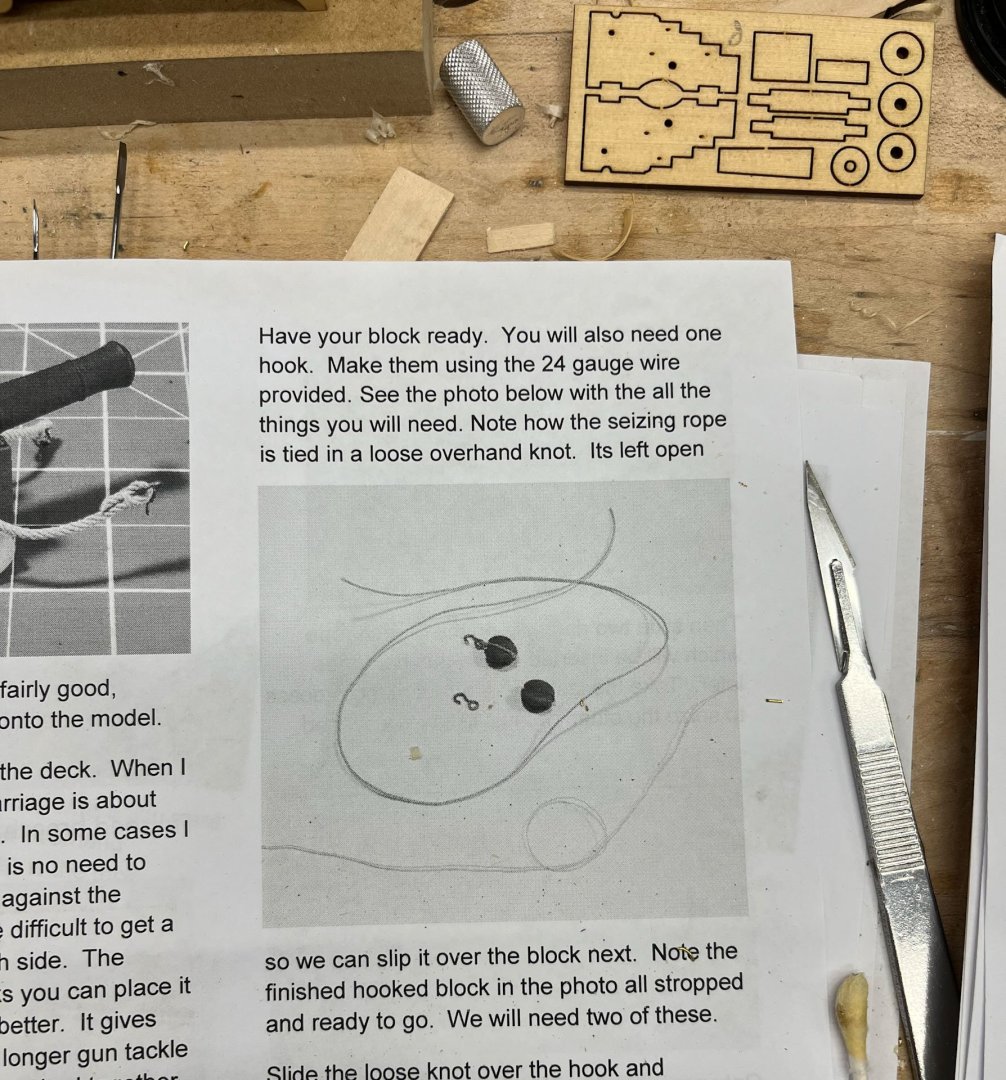
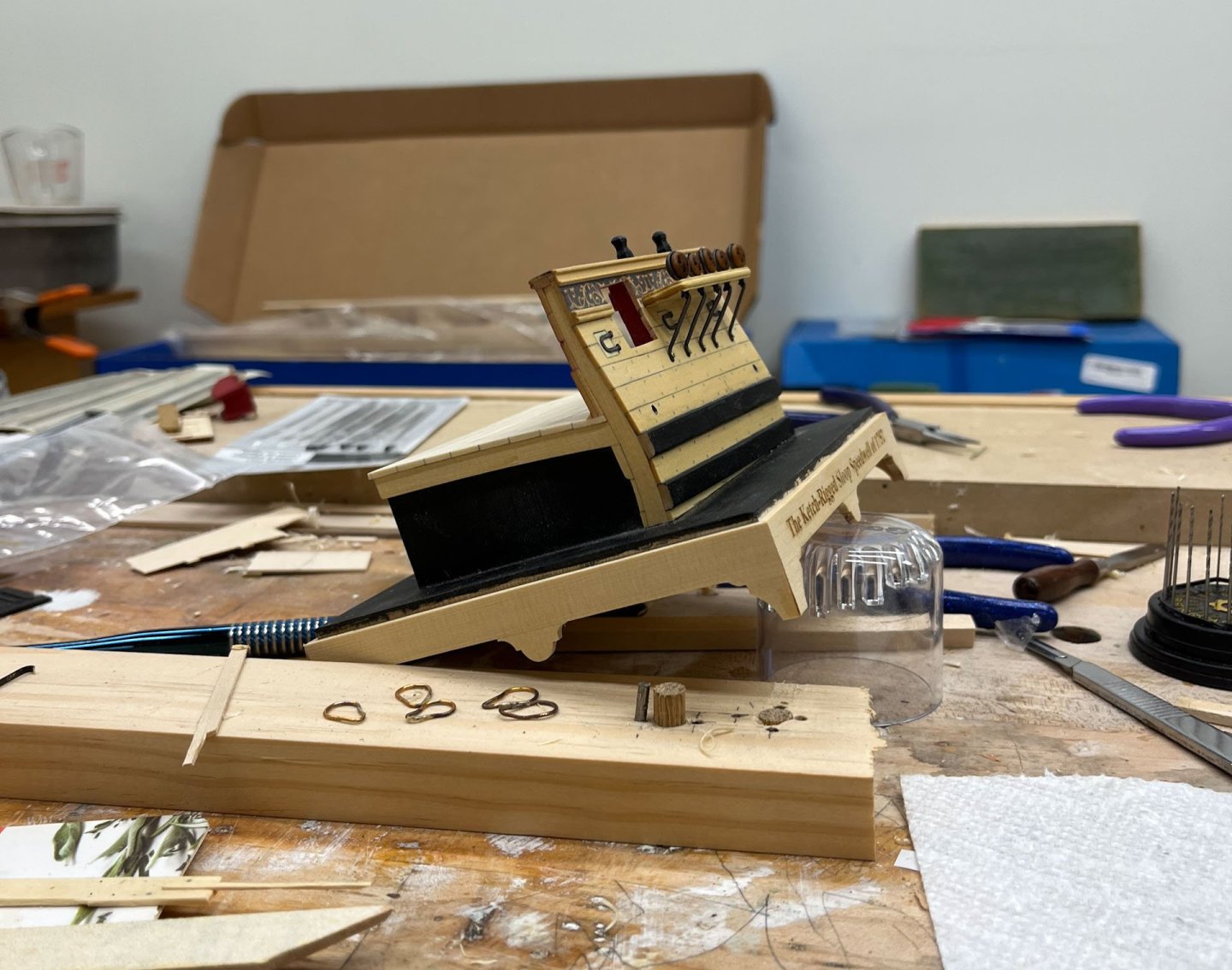
 Last I posted was October. Playing catch-up today. I have been working on the cannon and associated rigging. All the first time for me. Here's the various brass bits that I thoroughly messed up blackening on and had to resort to paint. I used 24 and 28g brass wire. Rings were soldered which in hindsight was unnecessary. 9 A first effort attaching block to Syren rope. I haven't seized them yet in the below pic but I did them as per Chuck's instructions using med viscosity superglue. Jason (JLong) said they looked acceptable so good deal. I worked on the carriage and quoin as well; here is my attempt at the handle done in a dremel with needle files. Worked fine. Its easy to get the handle not in scale; I kept having to make it smaller. I also made the breech rope seizings. I couldn't make it work without the Extra Hands. I found it cumbersome to try and glue in the breech rope anchors while the cannon was attached to the carriage. So I tried it without the carriage. Definitely easier. And thats where it all stands. I should be better about posting now that the holidays are over. thanks for reading Cisco


- 27 replies
-
- 12
-

-
- Speedwell
- battle station
- (and 1 more)
-
Hey Capt, thanks for checking in. Work has crushed me lately but I will have an update this weekend, I hope. Learning how to rig cannons with the help of JLong. Cisco
- 27 replies
-
- 3
-
-
- Speedwell
- battle station
- (and 1 more)
-
2025 MSW Holiday Fund Drive
CiscoH replied to ferretmary1's topic in NAUTICAL RESEARCH GUILD - News & Information
Done. -
how did you shape your scraper? in the past i have used a dremel wheel and fine files. its easy to (or hard not to) make the concave sections too big
- 1,215 replies
-
- 2
-
-
- sloop
- kingfisher
- (and 1 more)
-
you are working to a very high standard and extremely quick great job
-
Amazing! Thank you for the detailed explanation. i had to read it several times and go back and forth between pictures. it makes a lot of sense.
-
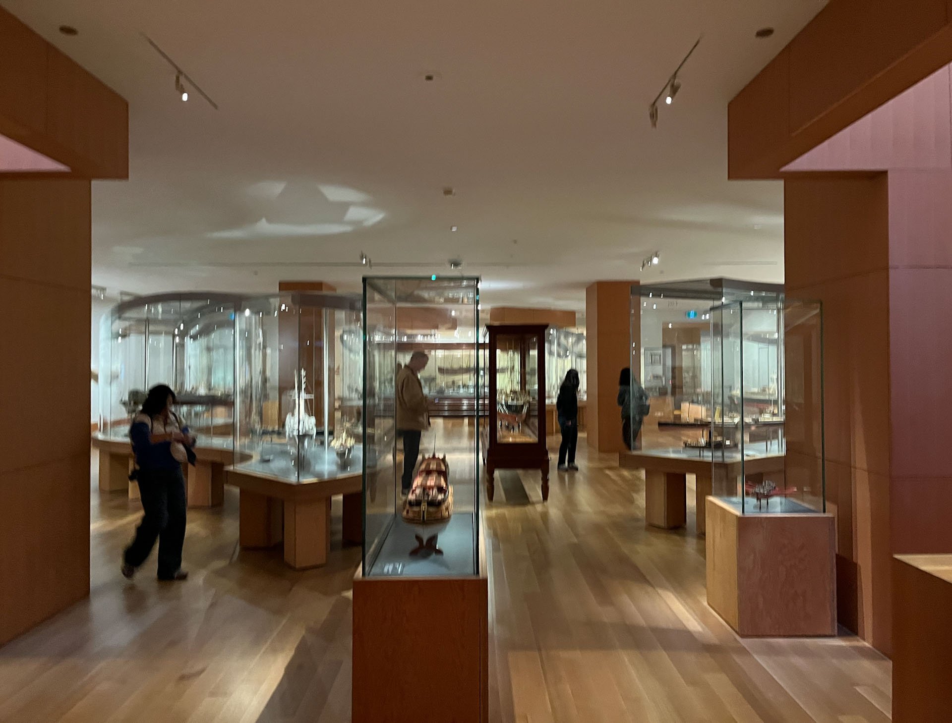
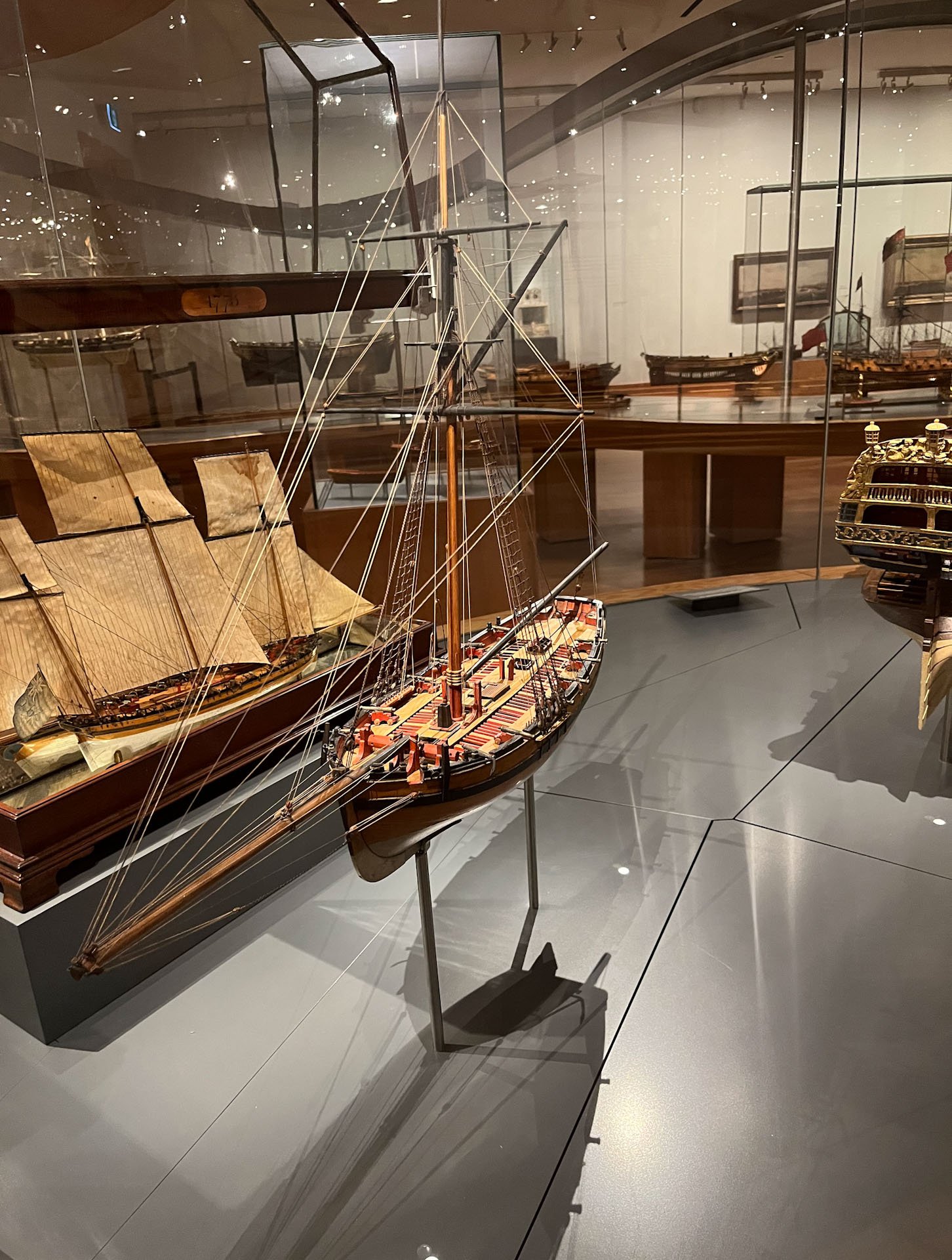
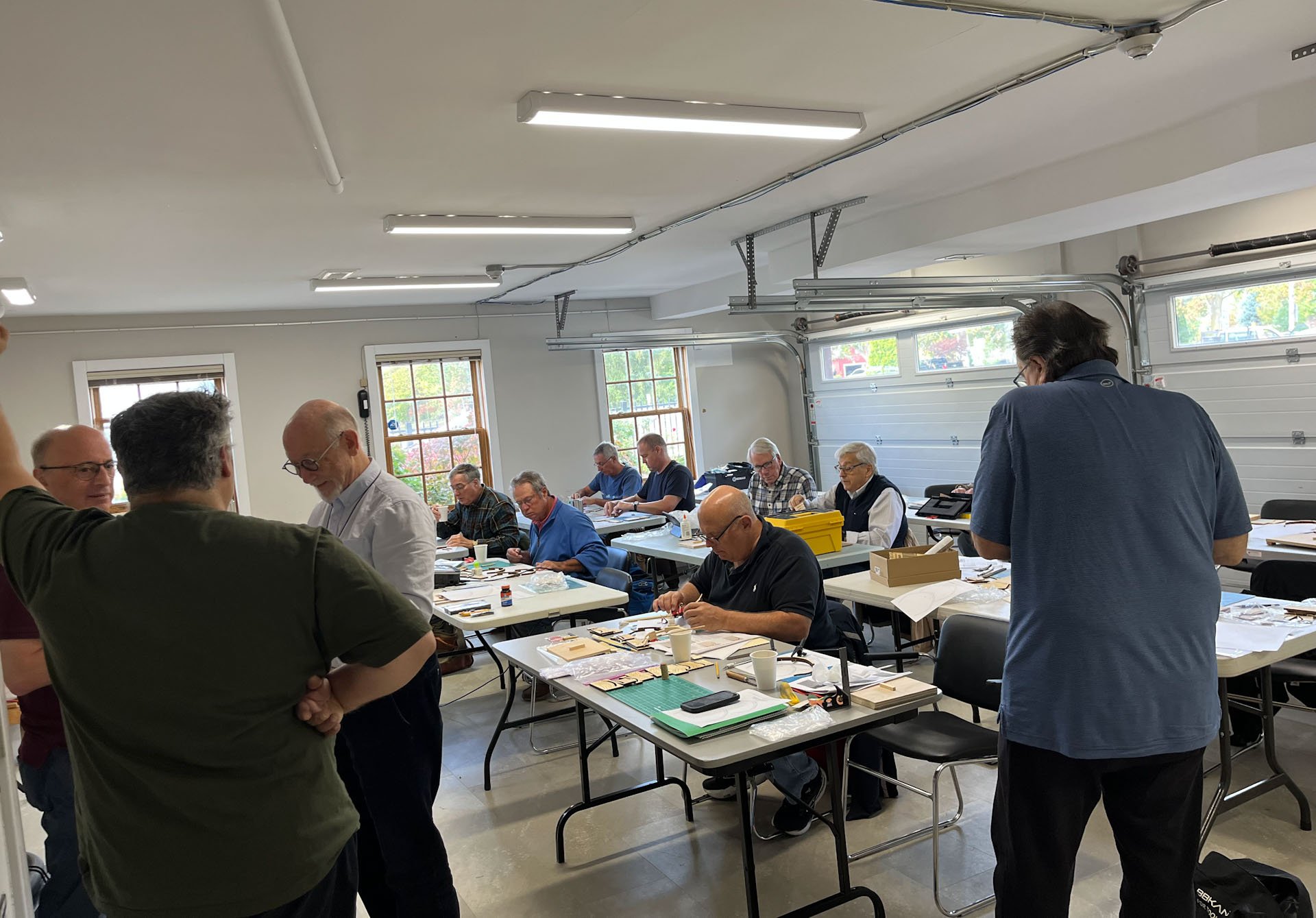
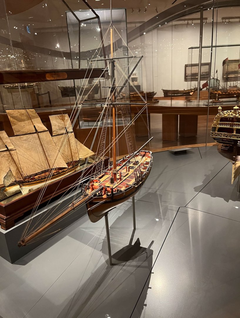
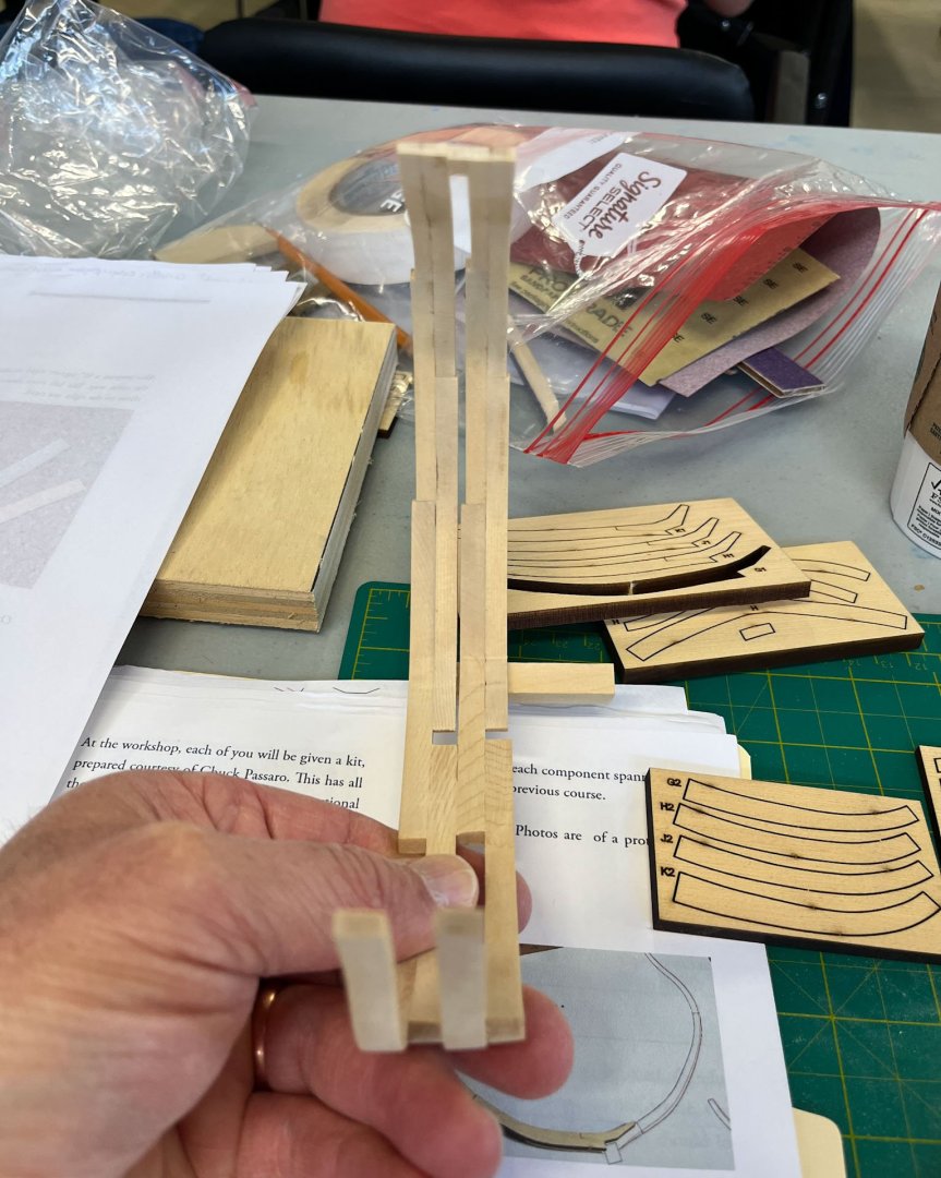
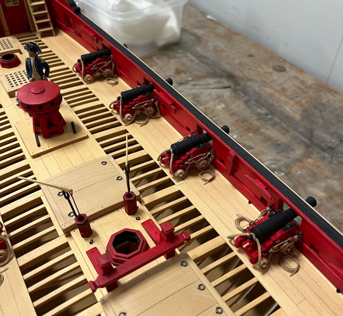
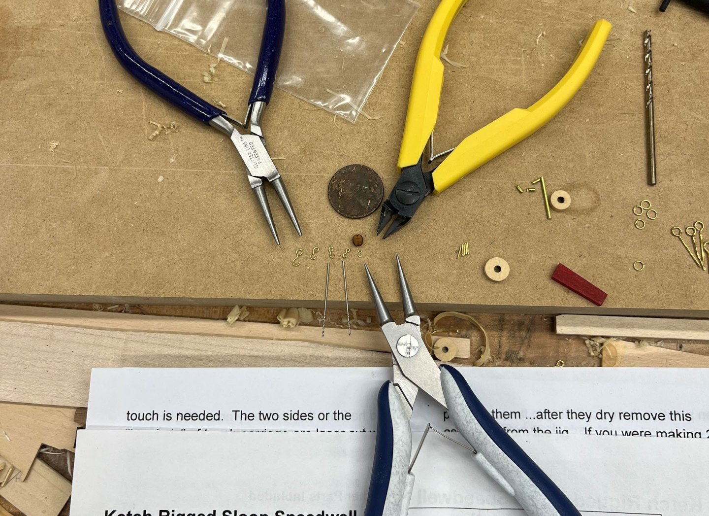
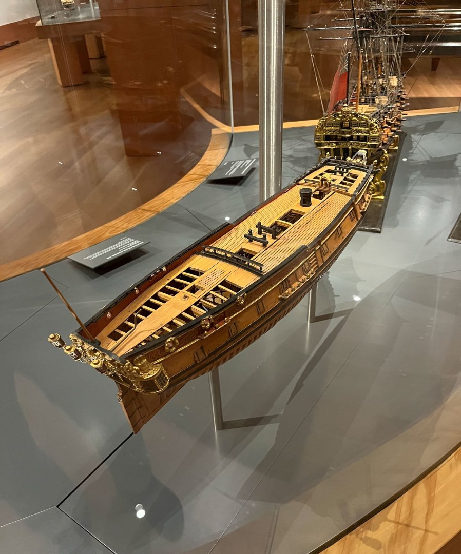
Good Evening MSW. Here in Delaware the weather has turned sweatpants and long sleeve plaid. First off I attended the last, or possibly the last so far until Chuck takes it over, Admiralty Workshops, held in beautiful Niagara on the Lake. This is a touristy town on the southern great lakes about 1 hr north of Niagara Falls. We were there off-season so it was quiet and not crowded. I flew but in hindsight should have driven. Stupid job time constraints getting in the way of my ship modeling. I landed in Toronto which was fine, got my rental car, and headed to the Art Gallery of Ontario which is about 20 minutes away with no traffic, haha. Parking was a struggle; eventually I used one of the kiosks on the side of the street and got the 3 hrs max which turned out to be plenty. If I was towing my family and kids probably not though. The floor I wanted was the Thomson Collection, a donated ship collection . All the exhibits are in flowing glass display cases. There are a lot of ships here, about half more modern metal ones, a quarter bone ships, and a quarter 17th-18th century. I always feel its a worthwhile trip if one thing speaks to you; here I really really liked the 24 gun navy board style Nightingale, 1:48. One i could see (someday far in the future) attempting to build. The Surly was there, I believe a close cousin to Cheerful. The rest of the museum is devoted to non-ship objects. The first floor has an incredible section of carved ivory and 17-18th century carved miniature wooden objects that defy belief. Many are carved on the inside; ie hollowed out balls with a level of detail and miniature-ism I would not have thought humanly possible. So don't go to this museum if you are a carver; you will leave depressed. The workshop itself was 2 days of comradery and socializing with fellow inmates. Chuck provided laser cut sections of futtocks that we glued together, then faired. One side was admiralty-style, the other side natural. Below is 2 of my sections being glued up; the final section had 4 "ribs." Here's a view during my 10:30am coffee break. Thank you Toni for letting me repeatedly borrow your scalpel. On the second day David gave some presentations on techniques. I had asked Chuck about how he formed the tiny hooks and eyebolts and rings on the Battlestation and this led to a demo. Chuck conveniently brought his Speedwell model and each time I look at it I see something new and challenging to replicate I missed the last time. Here's the cannons: David made some super-tiny rings from brass wire that I needed glasses to even see. I realized some purchases were in order. Clearly if I used the same tools as David I would magically achieve the same skill level. Here's what I wanted to do - make hooks that were proportional to the blocks Chuck supplied with the kit. To me the hooks look smaller than the blocks; ludicrously tiny. The pictures are deceptively magnified and I had spent some quality time before the workshop happily making giant-sized hooks. Once I got my new tools things were better. Purchases were: 1) teborg 46.9590 round nose pliers 5-1/2" long. Tips are a hair bigger than 1/64" diameter. My old set the tips were 3/64". 2) parallel jaw pliers, from Amazon. Very helpful squeezing rings shut and making bent wire flat. Generic made-in-pakistan. 3) Lindstrom flush cutting cutters #8147. My old ones were not flush and left a "beak" on all the wires I cut Below are my attempts to make hooks, left to right. I had tried my original round nosed pliers; huge hooks, then wrapping the wire around progressively smaller drill shafts which was very awkward and still were too big. With the new pliers I finally got a hook smaller than the block; Huzzay! I also ordered some smaller brass wire, 28 and 30g, which Chuck said will make it easier to form small parts. And thats where things stand tonight. Now I need to re-make my giant eyebolts and rings to a proper smaller dimension and then finally on to rigging the cannon. Thanks for reading Cisco


- 27 replies
-
- 15
-

-
-
- Speedwell
- battle station
- (and 1 more)
-
That looks great! Thank you for including your build process; its what is most interesting to us readers i think
- 32 replies
-
- 3
-

-
-
- NRG Capstan
- NRG
- (and 1 more)
-
JKC27 - i visited the museum on Tuesday. Driving in downtown Toronto wasnt much fun and the traffic on the highways around the city was also dense and unlovely. After driving aimlessly looking for nearby parking garages (all of which were tiny and full) i paid the street kiosk meter 15$? for 3 hrs and was 2 blocks away, which is what i should have done from the start. I only have 2 hours of focus anymore so that was enough time for me; the museum ship collection is Amazing and the carved wood/ivory wing was also pretty unbelievable. definitely worth the work getting there.
-
Donna there have been rumors your table saws are able to be purchased again?
-
Excellent planking sir! looks great
-
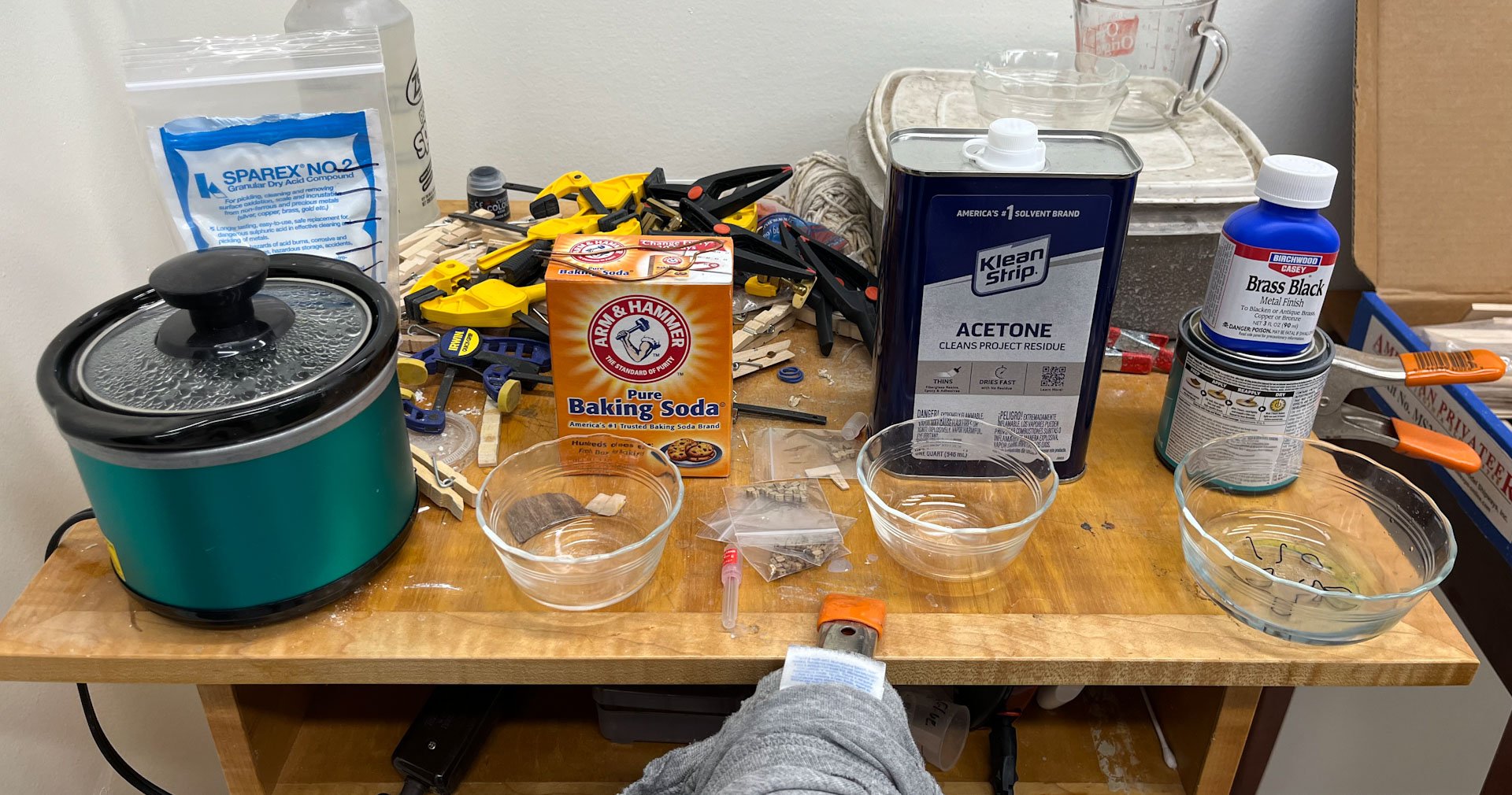
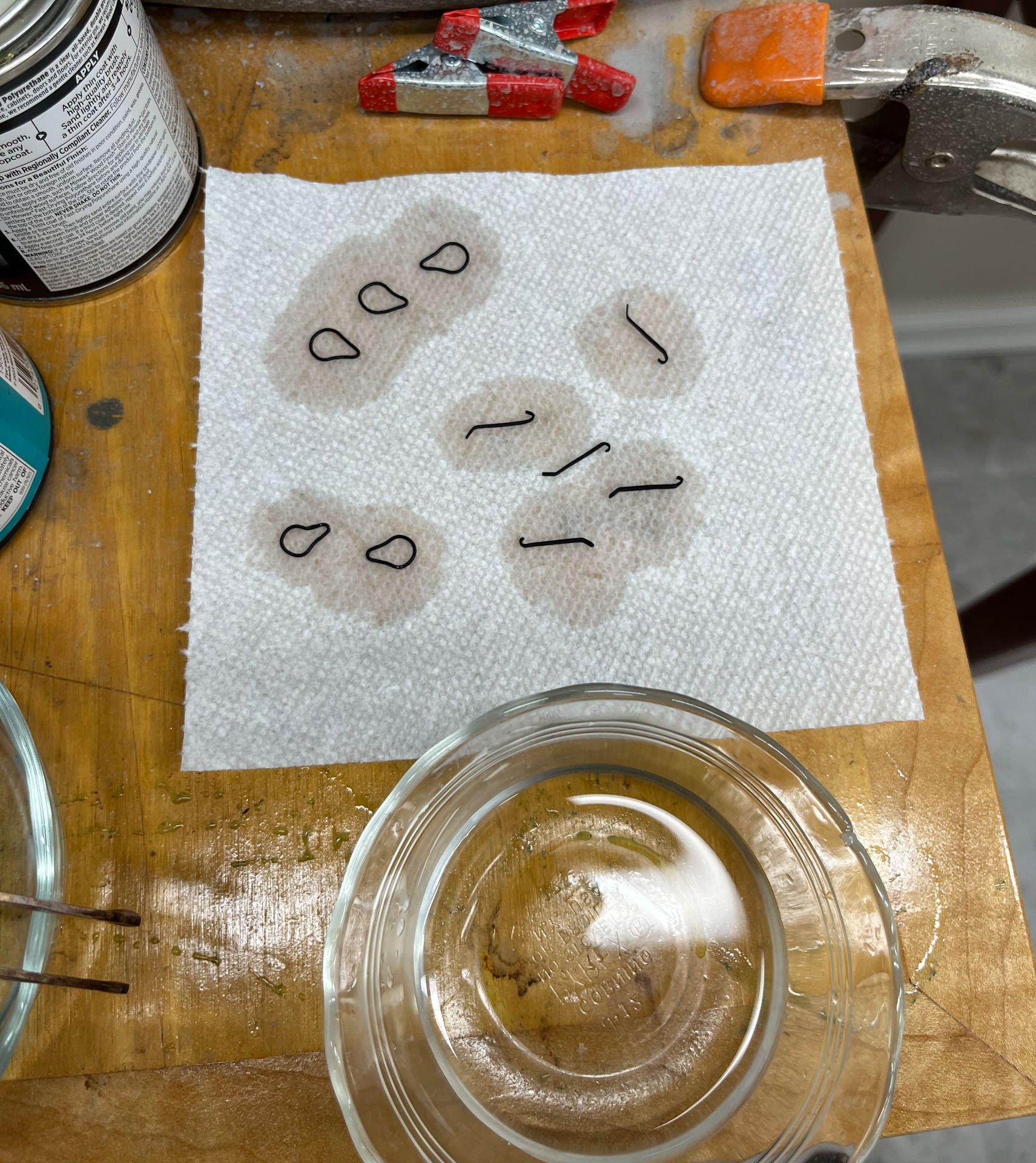
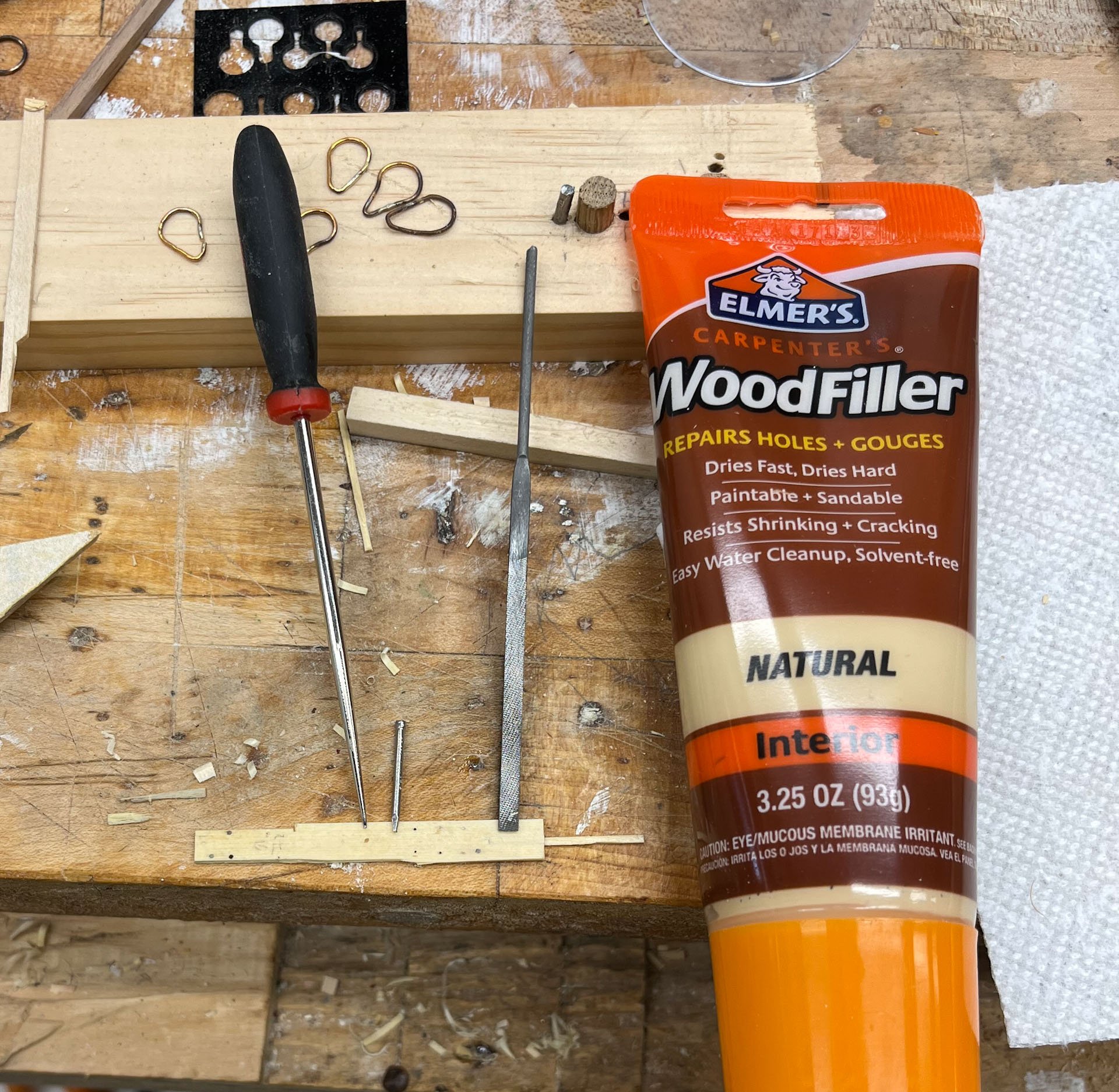
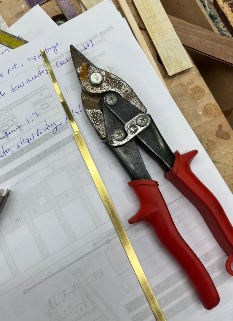
Happy Saturday afternoon. I have met the challenge of making my own deadeye straps and strops headon, or possibly head first, and have emerged. Call it a draw. First off, the kit comes with perfectly serviceable laserboard? (a black plastiky looking material) strops and straps which look great and are easy. So you don't have to go down the road I did. The strops - I wrote about them in my last post. The hardest part, by far, is making strops that are the same size. I made at least 10 versions to get 5 that were close. The below jig helped and you can see all the different versions I made. The nail had to be adjusted 6 times. Also keep in mind that because 2 of the deadeyes are smaller, 2 of the strops will be smaller as well. At least silver soldering went fine. Thanks Greg (dvm27; his advice is a recurring theme in this post) for your recommendations posted under Silver Solder. I use Euro Tools inc silver solder paste SS 65 and it works great. The straps were straightforward. Hardest part was forming them; no one makes strips of brass in the size I needed. I had a length left over from my AVS used to make the rudder hinges that was perfect, but it wasn't long enough. Model Shipways doesn't sell the brass strips on their website that I could find. So I cut my own strips a little wide and filed them to width. Tedious but doable. unsurprisingly it was hard to make the strips the same length. And to drill the hole for the pin in the same place. And then it was time for my Arch Nemesis. Blackening. I had done several trys on my AVS rudder hinges. My recipe then was 220 grit sandpaper, acetone soak, and brass black diluted 1:10 ish. They ended up splotchy, the soldered areas didn't take well, and the blackening that did stick came off with any manipulation. Super frustrating. I ended up painting them all. But I really like the dull grey/blue/black colour of chemically blackened brass so I went at it again. Here's my setup, following Greg's post about blackening to the letter. 1) Sparex, which is I think an acid etch solution. I used distilled water for everything. Directions for mixing the Sparex are on the bag. I heated the water in the micowave until it was hot to the touch, then poured it into the heated crock pot and mixed in the powdered Sparex until it dissolved. I left all the brass pieces in the solution for 15 minutes. Any handling from here on out was with copper tongs. 2) washed with baking soda mixed in warm distilled water for a few minutes. The solution bubbles when you put the metal pieces in. 3) acetone wash for 10 minutes. 4) BrassBlack mixed 1:10 with warm distilled water (or maybe even more dilute) for 15 minutes, flipping the pieces every few minutes with my copper tongs. 5) and finally below, rinsing in warm distilled water and drying. THIS time I got 99% coverage and very good durability. The solder joints all blackened evenly and were invisible. Even bending the strops (I used a jeweler's pliers with a strip of tshirt taped to the jaws) almost no flaking. Nice! Next I attached the straps to the stropped deadeyes and drilled holes for the pins. Chuck's directions show the straps starting close to straight up on the right, then becoming more angled as you work your way left. Mine didn't cooperate. Some straps were a little longer than others and I re-arranged which one went to which strop several times until I got close to an even run. I pinned the first and last strap and then attempted to fill in the middle three in a fan pattern but ultimately they decided they wanted to be parallel. This led me to moving the pin hole of the strap on the far right so all the straps were parallel, which of course left me with a glaring pin hole to fill. Instinctively I knew anyone looking at my model would remark on this pin hole and snicker so the stakes were high. I used a scrap wood piece, below, which I had originally used to pick a method of trenailing, to test some repairs. First I filled the hole with sawdust and white glue, apparently a tried and true method. The awl on the far left below is pointing to that repair, which made the hole More Obvious. The file to the right is pointing to my second attempt. I drilled another hole and removed a strip of wood in the middle of the plank overlaying it and used a dutchman to patch. Its very hard to see in the picture and it worked well. Then in the middle (pointed at by the nail) I used some Elmers Natural woodfiller, same stuff I used to fill the planking trenails, and the drill hole disappeared completely. So low tech it is. I filled the hole with the Elmer's stuff and its fixed. Here's a shadowed, out of focus pic of the final result. To move things along I will cheat and paint the brass pinheads black. If anyone reading ends up making straps like I did I assume they will be slightly different lengths like mine. You can fool the eye by making the bottom of the straps even. Once the pins are painted black any irregularities with their placement will disappear. I hope. Thats it for today. I think the cannon carriage is next. I will probably try to make the hardware (for anyone smart the kit comes with perfectly serviceable black wire and some brass loops I think) and test my nascent blackening skills. thanks for reading Cisco


- 27 replies
-
- 9
-
-
- Speedwell
- battle station
- (and 1 more)
-
How do you Chuck, of all people, have time to build puzzles? and I like the second image the best
-
great job Chris. your longboat looks professionally built. i got this model as an intro to ship building because i figured it was small and would be quick to build. as youre finding out it's actually very complex and not ‘easy’ atall; i think mine took me 6 months to build.
- 38 replies
-
- 3
-
-
- 18th Century Longboat
- Model Shipways
- (and 1 more)
-
excellent explanation
-
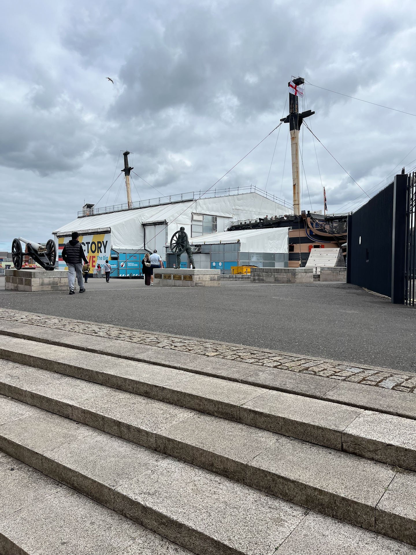
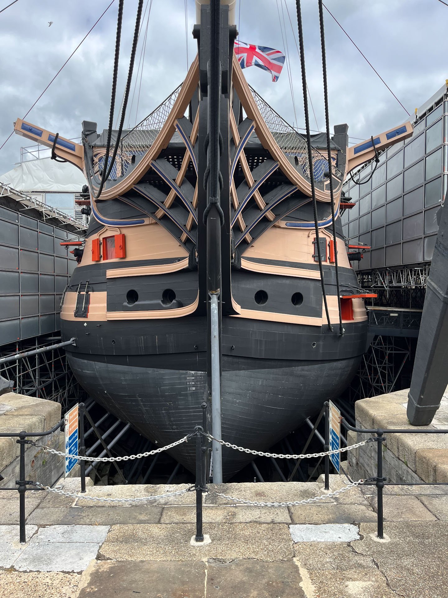
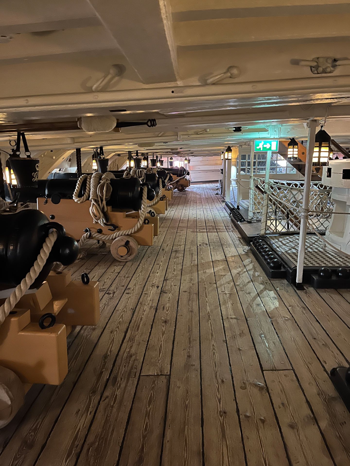
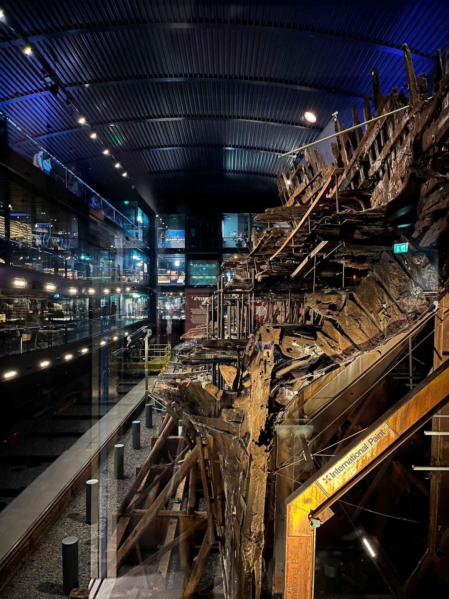
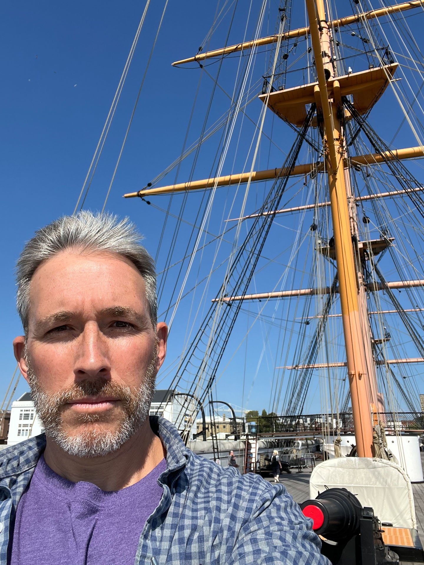
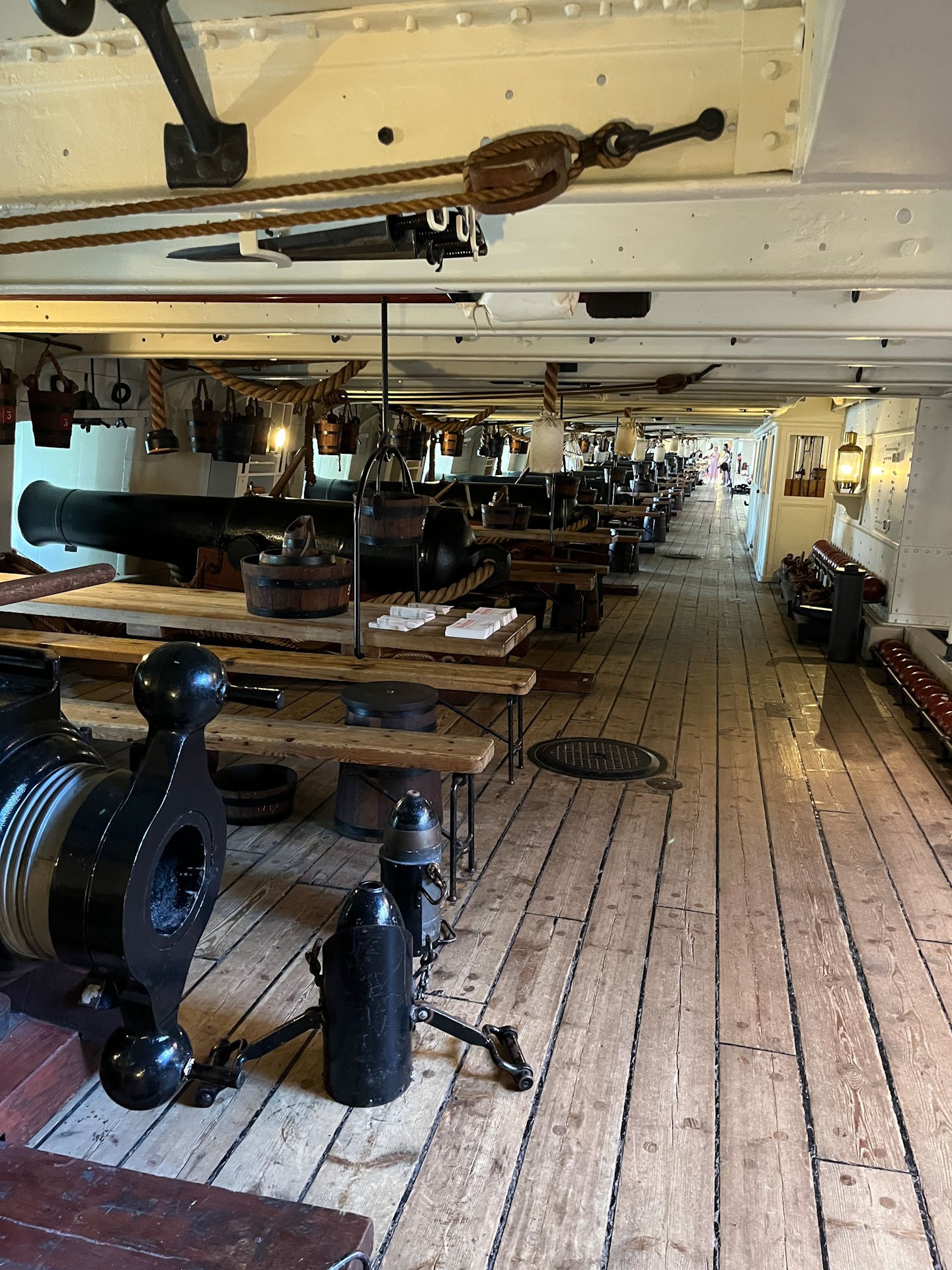
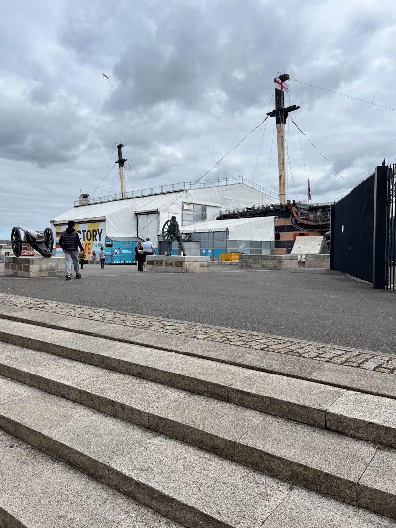
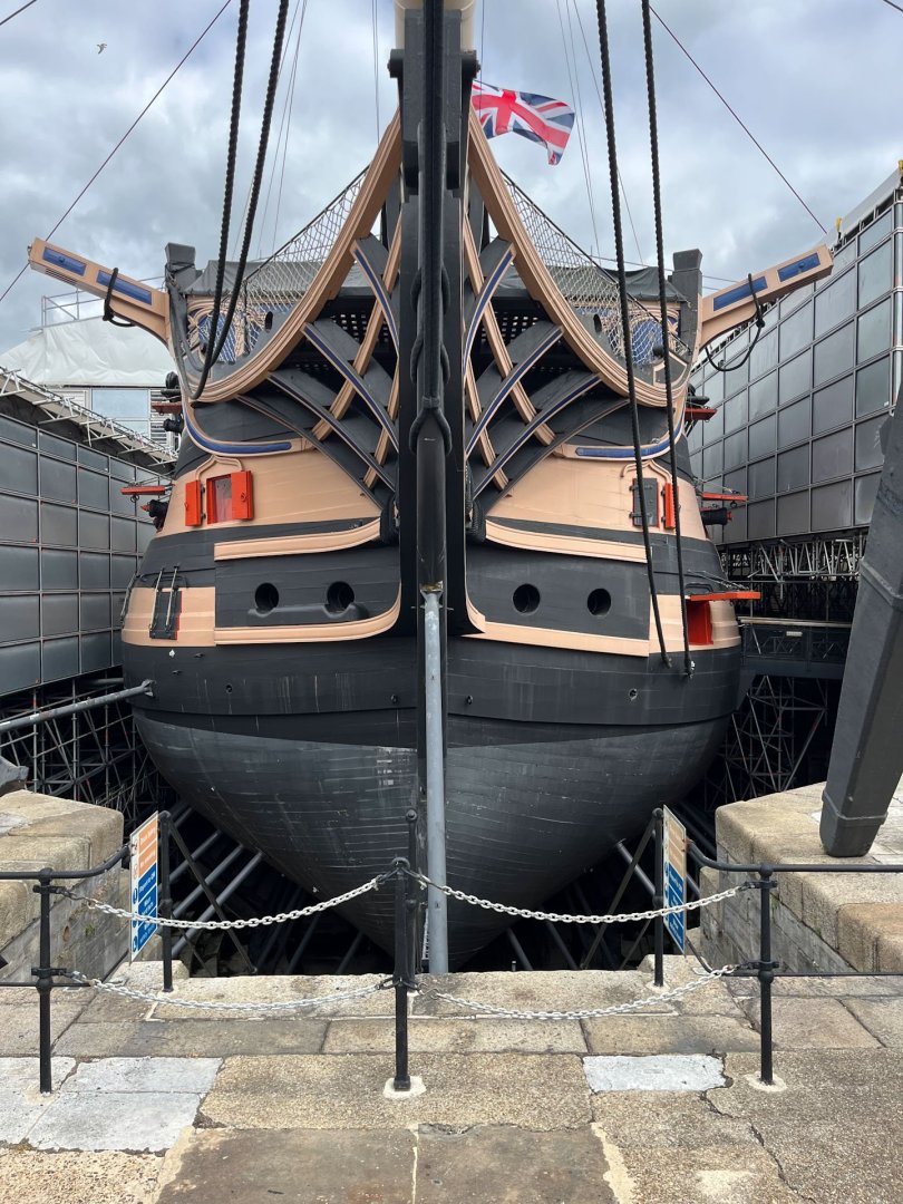
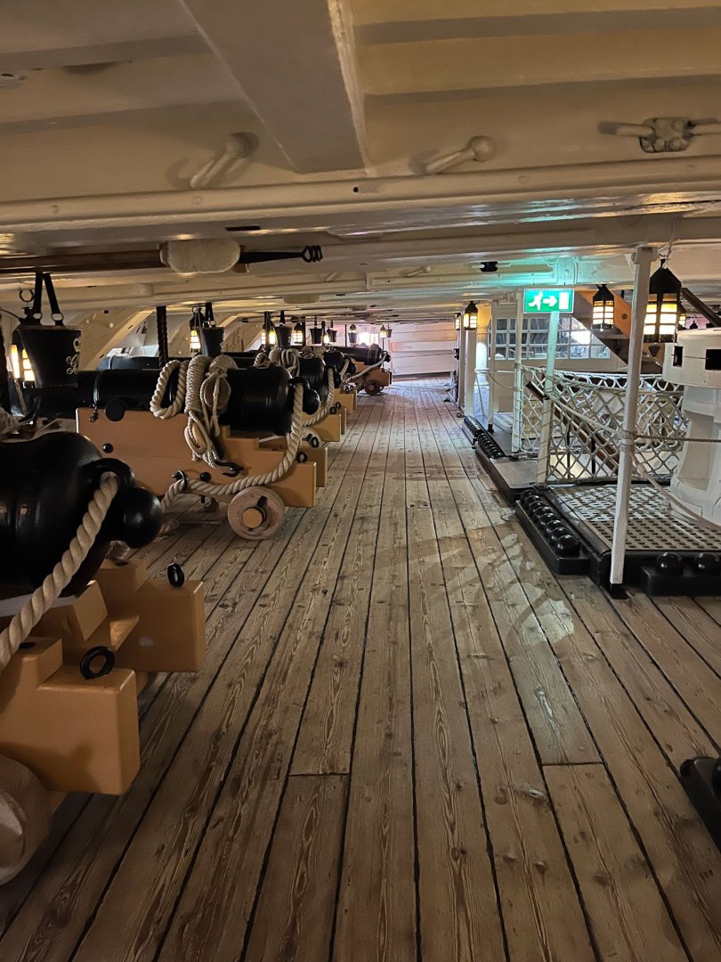
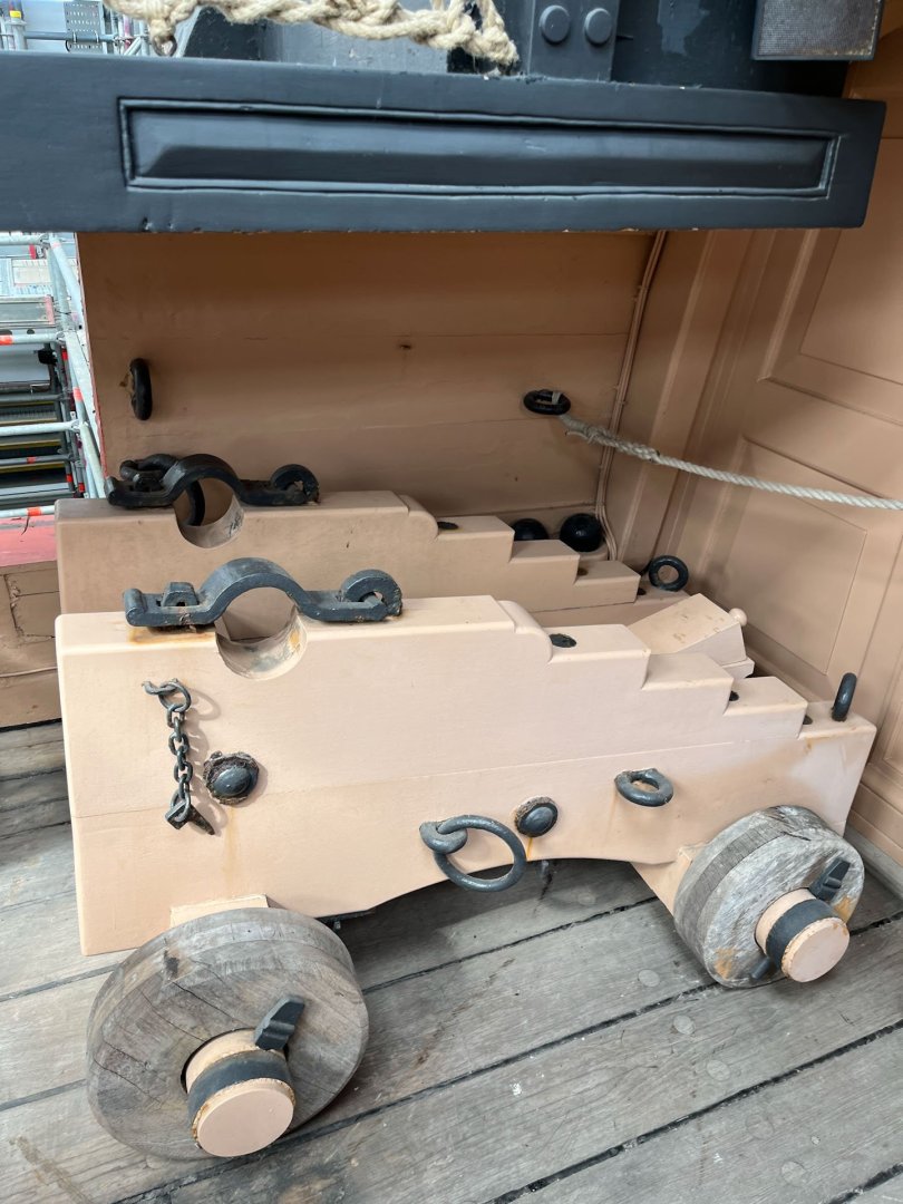
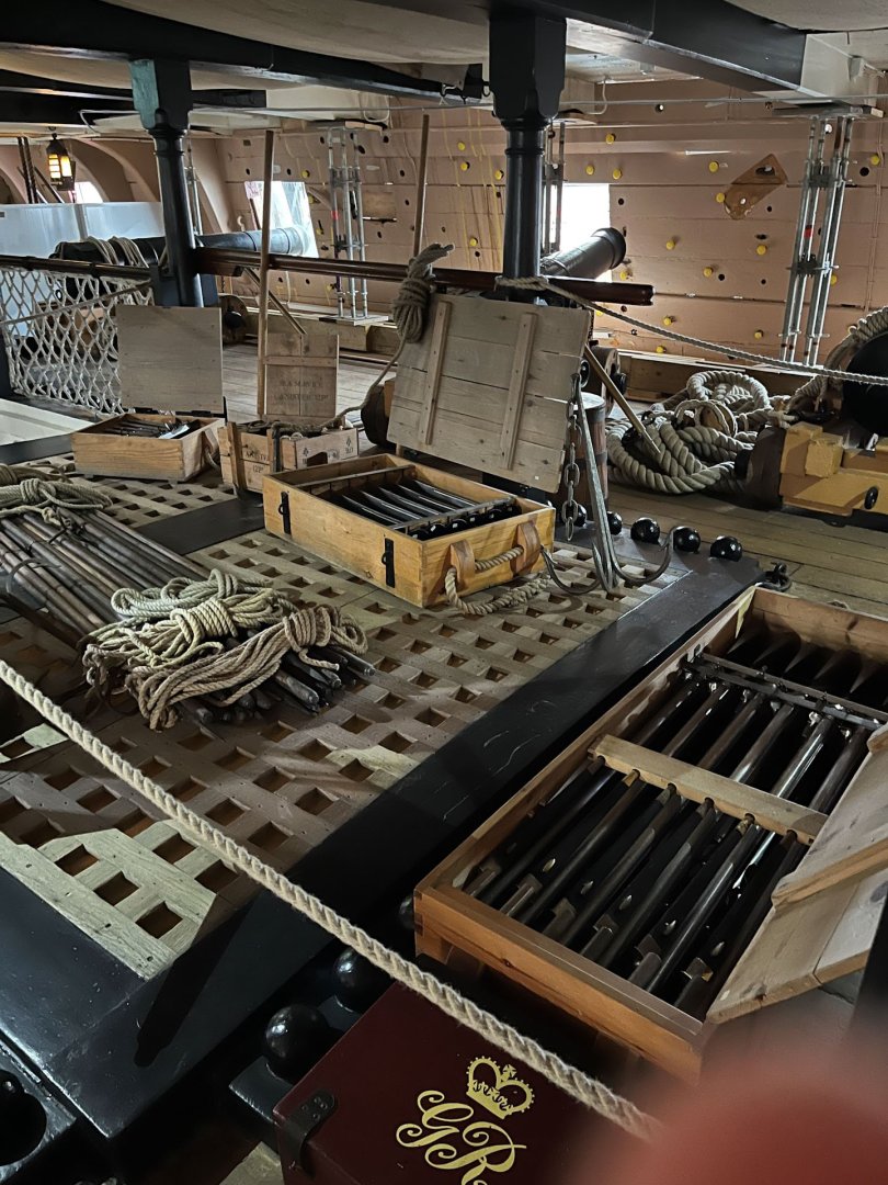
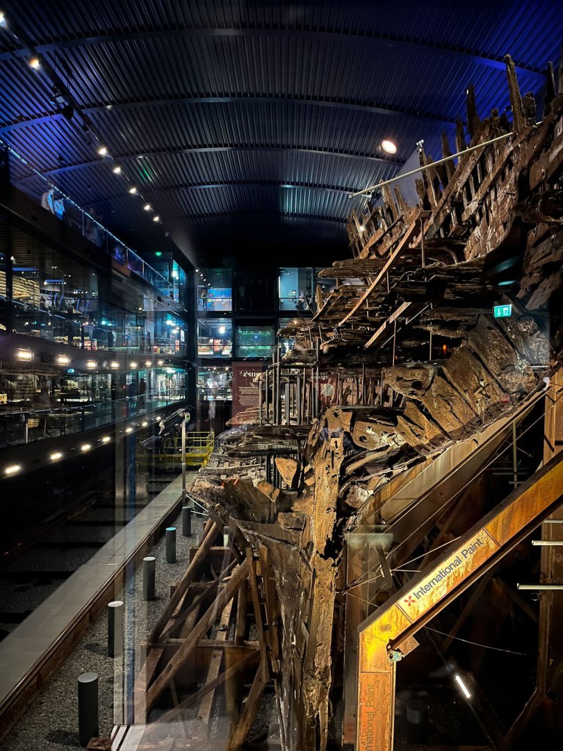
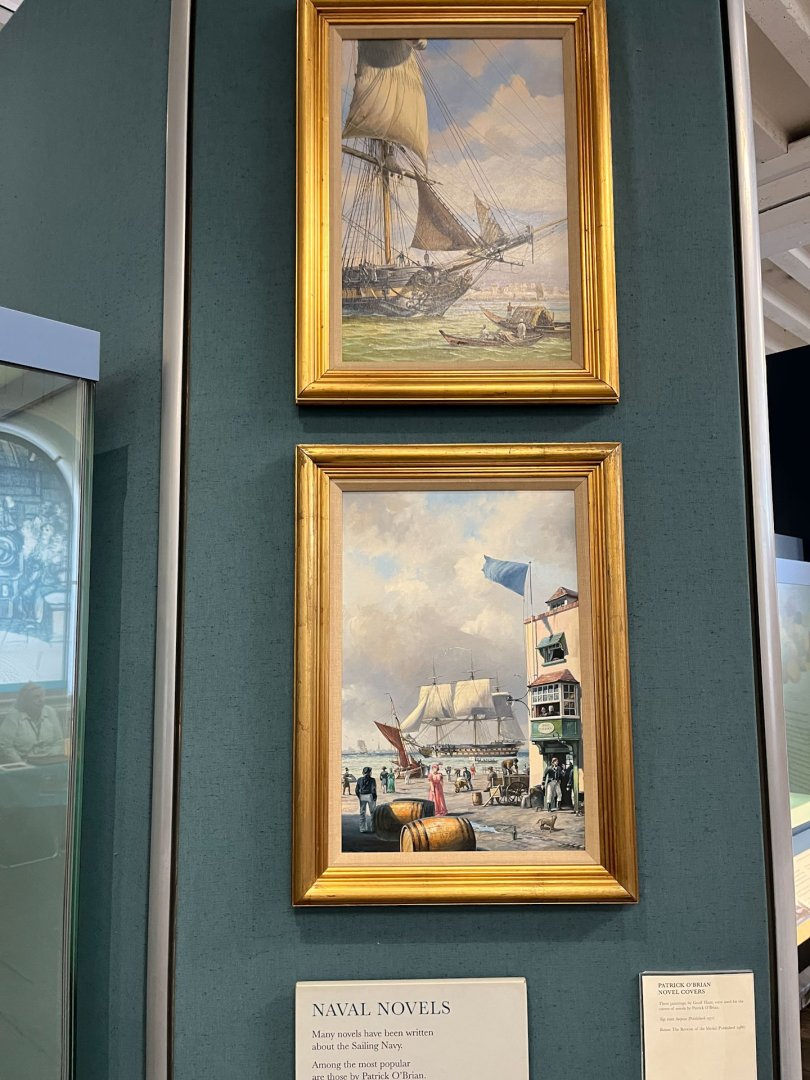
Well its been a bit. The summer has been flying along! We went on vacation to England earlier this month for 9 days and saw lots of touristy sights in the Southwestern parts; London, Stonehenge, Bath, Land's End, many others. Then with 1 day to go before taking the train back to Heathrow I was let off-leash for the day in Portsmouth. We all did our own thing (wife and kids went shopping); obviously I bee-lined for the Historic Dockyard. So so cool. Here's Victory, who is under intense refurbishment. My modeling buddy Jason was hoping for some rigging pictures but nope other than the fore and mizzen its all been taken down. Here she is from the front. I noticed the bottom of the wales don't line up; not sure if thats purposeful. You can take a self-guided tour which I recommend; it was set to music and followed along the weeks before Trafalgar and helped set the mood. There were a lot of boxes of equipment on the inside decks that would be great details to add to a model. Since this log is about the Speedwell battle station and I have a cannon to model in my future I got a lot of carriage pics. But I'm not sure how accurate the equipment is; the barrels were mostly wooden and I assume a lot is recreated. I hope the pics will at least help me get the size of rings and bolts proportional. Next up was the Mary Rose museum, about 1 block away in the same area. While I don't have as much interest in this era it was an amazing museum mostly due to all the personal effects found on the wreck that are very artfully displayed. The ship apparently was overburdened (if one deck of cannons about the poop is good, 2 decks must be twice as good - it turns out no) and turtled in a gust during the Battle of the Solent 1545. Many/most of the crew was trapped in place, and anything below the sand that wasn't prone to rusting was well preserved in the occupant's cabins - trunks full of clothes, personalized belongings, and many many bows and arrows. Ironically the wreck itself wasn't as exciting as all the stuff in it. Then the Naval Museum. It tried to cover a long era of naval history and managed to skim over most of it. I did really enjoy seeing 2 Geoff Hunt paintings (no ropes or anything to keep you from touching the pictures. Europe is very trusting) from Patrick O'Brian novels. And finally, running out of steam haha, I toured the Warrior, a transition steam and sail powered iron hulled warship. Its a bit past my era of interest so I didn't take many pics. Interestingly it had the least number of tourists of anything I visited at the Dockyard. Here's me looking tired and windswept. The ship felt very steampunky. Check out this row of cannons; very menacing. I needed a week to recover from vacation. And work, as it always does, came out swinging when we returned. Today was the first day i could summon the energy to work on Speedwell. Chuck includes black plastic deadeye strops. They look convincing and the deadeyes are easy to insert. Obviously this would never do and I set out to further delay my completion date by making brass ones. It took a bit to get the old brain running again and there were some false starts. I think I recall most people make a jig of some sort to make the strops the same length. I drilled a hole for a dowel and placed a nail next to it to construct an oval-shaped brass wire loop; on the left of the below pic are the first 2 versions that turned out to be too big. On the right are 3 of the plastic kit strops for comparison. 2 of them I tried to cut open and heat over a candle to bend them straight and measure their length. They both immediately stretched and melted so no go. Silver soldering went pretty well (for once) and on the second strop I moved the site of the joint more downwards toward the smaller loop so it would be hidden in the chainplate. I made a brass deadeye strap (lower part of below pic on left) to test it out. Works well and looks pretty much identical to the kit plastic one on the right. Below, on the left, is Version 2 of my deadeye strop with deadeye in place. You can see the lower loop sticks out too far compared to the plastic kit version in the next chainplate slot. But getting there. And thats where it stands tonight. for those of you that managed to read this far, thank you, and have a calm evening. cisco


- 27 replies
-
- 20
-
-
- Speedwell
- battle station
- (and 1 more)
-
i’m definitely not doing sails now. All this fine rigging looks suspiciously like work
-
really really nice planking job. i used my first boxwood a few weeks ago and i found it to be a brittle wood as well. i think its just the way the wood is, especially compared to the kit basswood.
- 38 replies
-
- 3
-
-
-
- 18th Century Longboat
- Model Shipways
- (and 1 more)
-
either a long sliver or make a new plank from wider stock and trim it to fit. but my vote would be for the sliver. i dont think anyone would notice unless you pointed it out
-
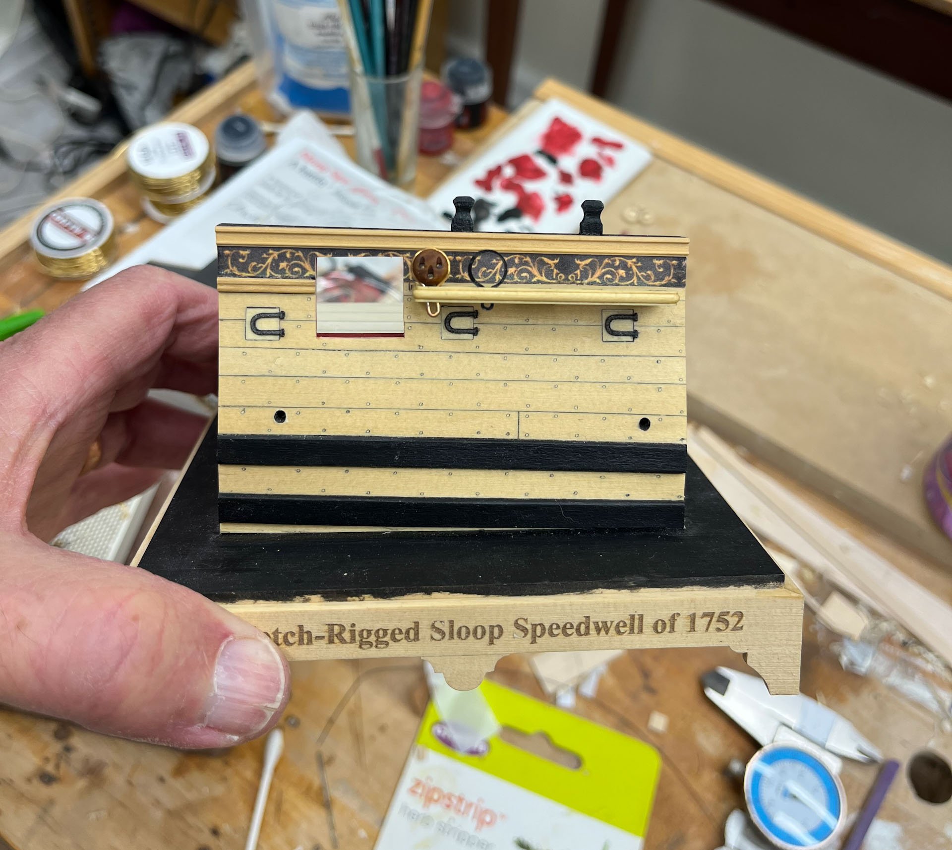
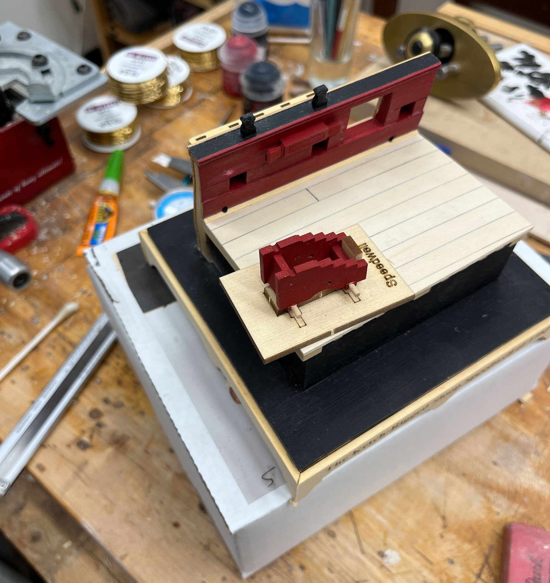
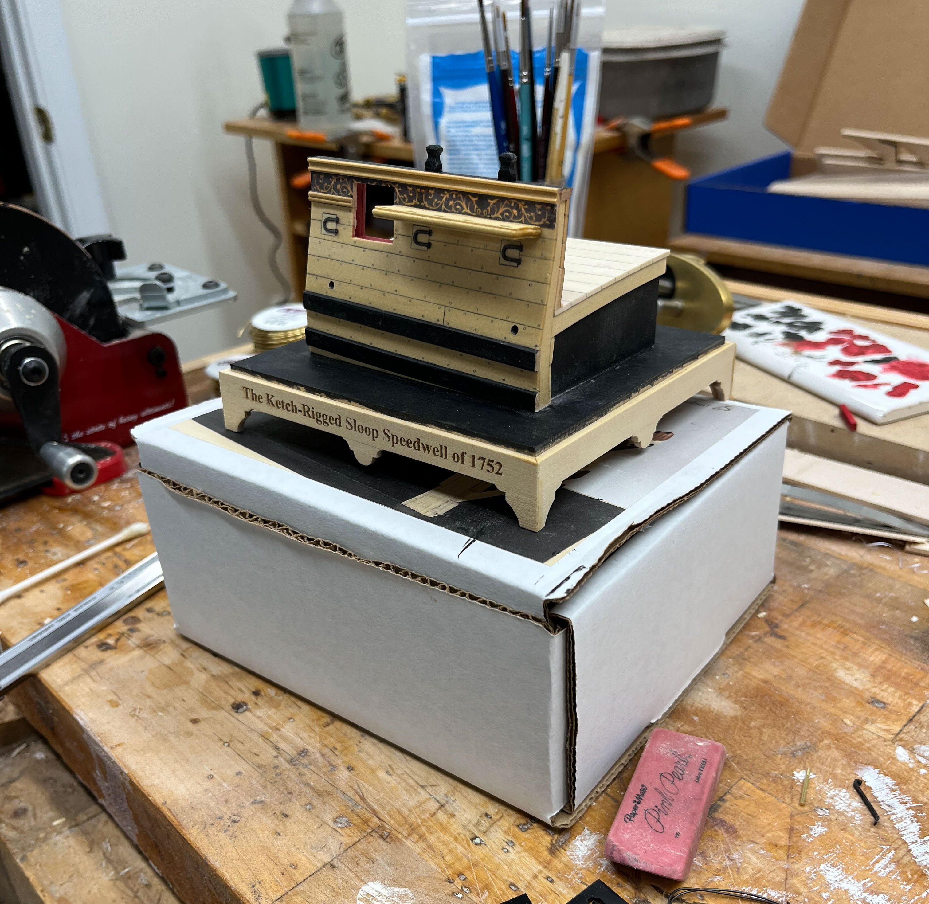
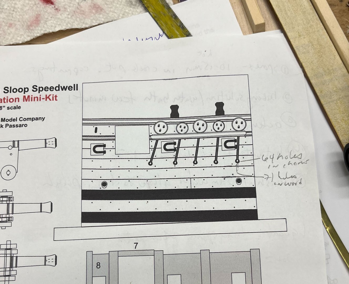
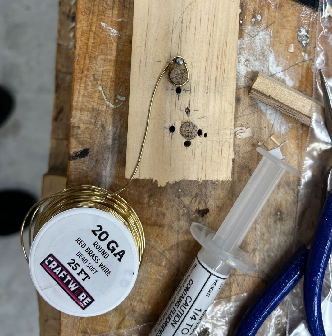
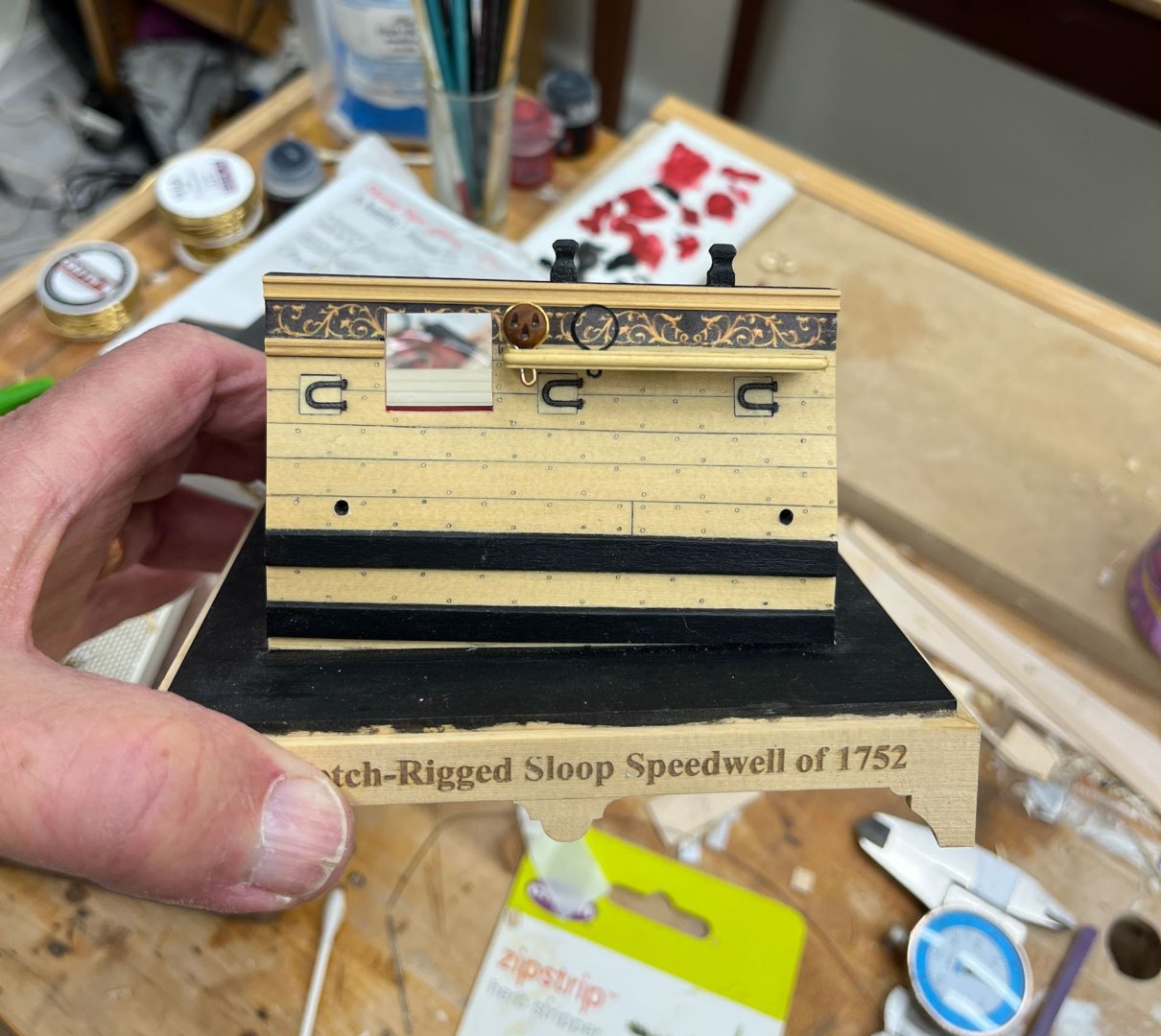
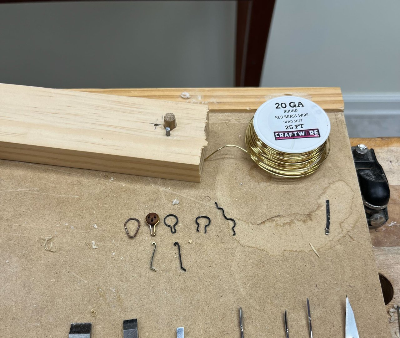
Good Thursday night MSW. A brief update tonight, more fine tuning than impressive progress. I finished the cap railing and moldings and sanded down the cross sections of the planking on the sides. Then I added the channel, which had to be sanded down thinner to match the width of the molding. I wasn't confident it would stay put with only glue so I pinned it as well. I managed to drill all the way through the bulwarks with all 3 pinning holes so beware future builders. I used epoxy and 20g brass wire which fit the holes loosely allowing me some wiggle room, and yellow glue. It's pretty solid now. After it was fully dry I realized I put the channel in upside down (the edge slots for the deadeye strops are not the same at each end, one is closer to the edge than the other) but I can't easily unattach the thing so its staying. I noticed in the Speedwell book (Vol II, pg 47) Greg and Gave show the deadeyes all the same size. They also chose to add a swivel mount directly over the channel, in between the 2 bolsters. I don't think I'm doing the swivel but maybe my brain will betray me. Again. We'll see. It might make the model a little too busy. Then I made the bolsters, which were straight-forward sanding exercises and pinned them as well. I used superglue for the pins. Both feel secure. And finally I manned up and attached the base pieces. They were not perfectly square to each other so I have some sanding in my future before I add the curved molding to ease the transition to the base. I also added the waterway piece, which in hindsight should have been holly so it matched the decking instead of the AYC i used but oh well. I also drilled out the scuppers and used #2 pencil to darken them as per the directions. They don't connect and you can't tell. and now I started on the cannon carriage. Thats it for tonight. Tomorrow the family and I are flying to not-sunny old England for a week of vacation. I bargained hard for a day to see the Victory and in return had to give up all control of the other 6 days. Pictures will be posted. thanks for reading, Cisco


- 27 replies
-
- 14
-
-
- Speedwell
- battle station
- (and 1 more)
-
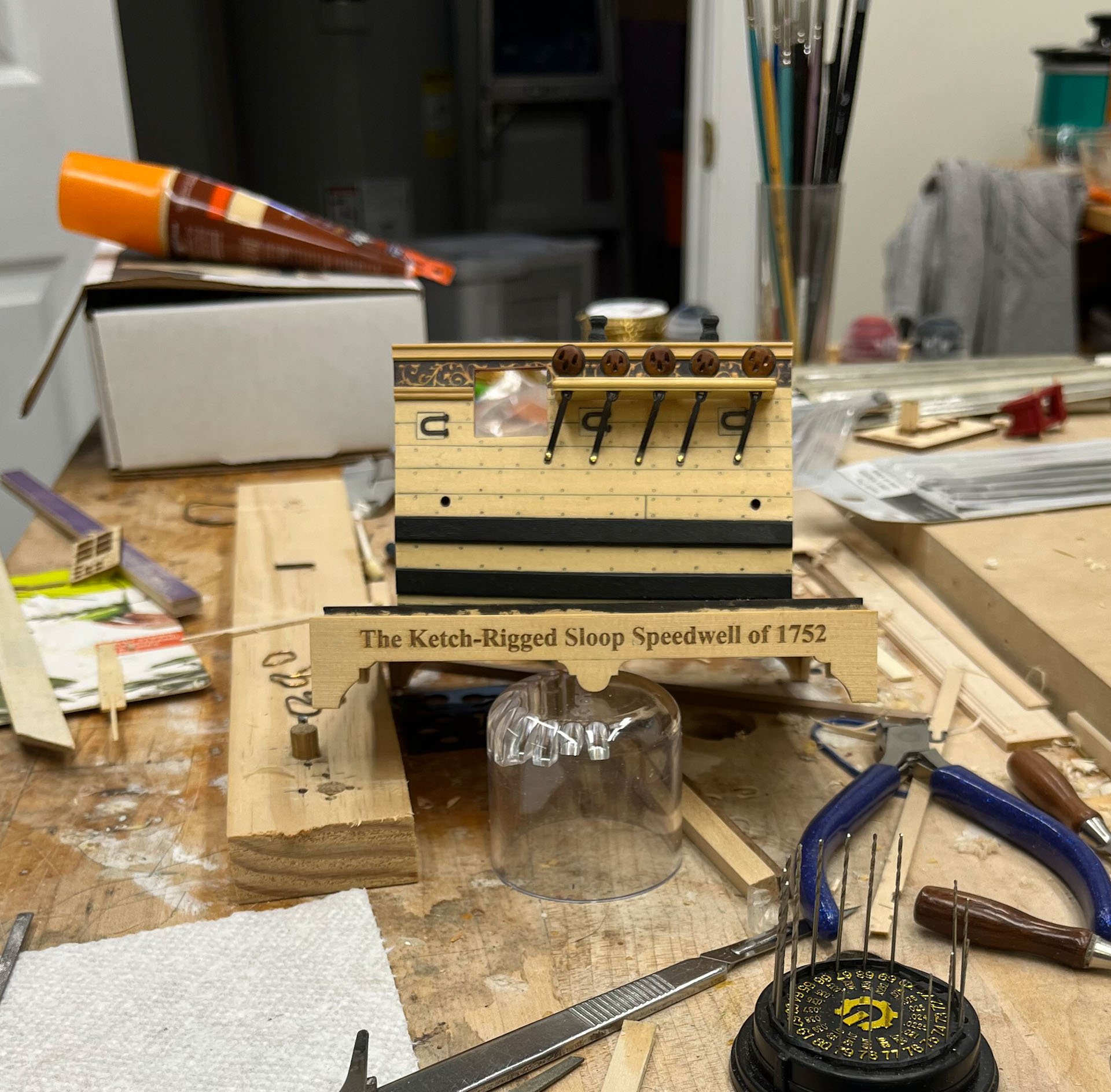
Nothing is more rewarding than dealing with the public. And i too hope Chuck produces the Battle Station as a regular kit. Its small but packed with detail and perfect for introducing the use of Syren rope and other Syren materials to rig a practice cannon. I won mine at the CT conference and could have gotten a mini table saw but picked the kit instead. And I have so far really enjoyed building it.
-
I really liked the Old Blocks. Very Minecraft-y