
CiscoH
-
Posts
384 -
Joined
-
Last visited
Content Type
Profiles
Forums
Gallery
Events
Everything posted by CiscoH
-

Fret saw versus power saw
CiscoH replied to Quimp Slattery's topic in Modeling tools and Workshop Equipment
i do almost all my work with hand tools. mostly the powered stuff is in the garage but thats only used to cut billets into strips. if i bought strip wood then there would be no need for noisy powered tools. -
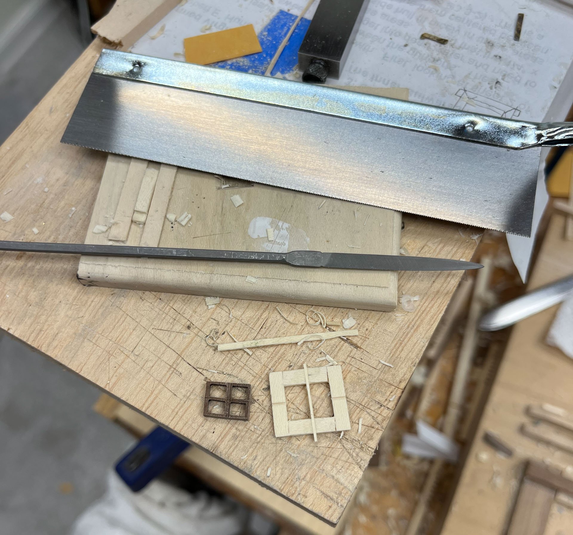
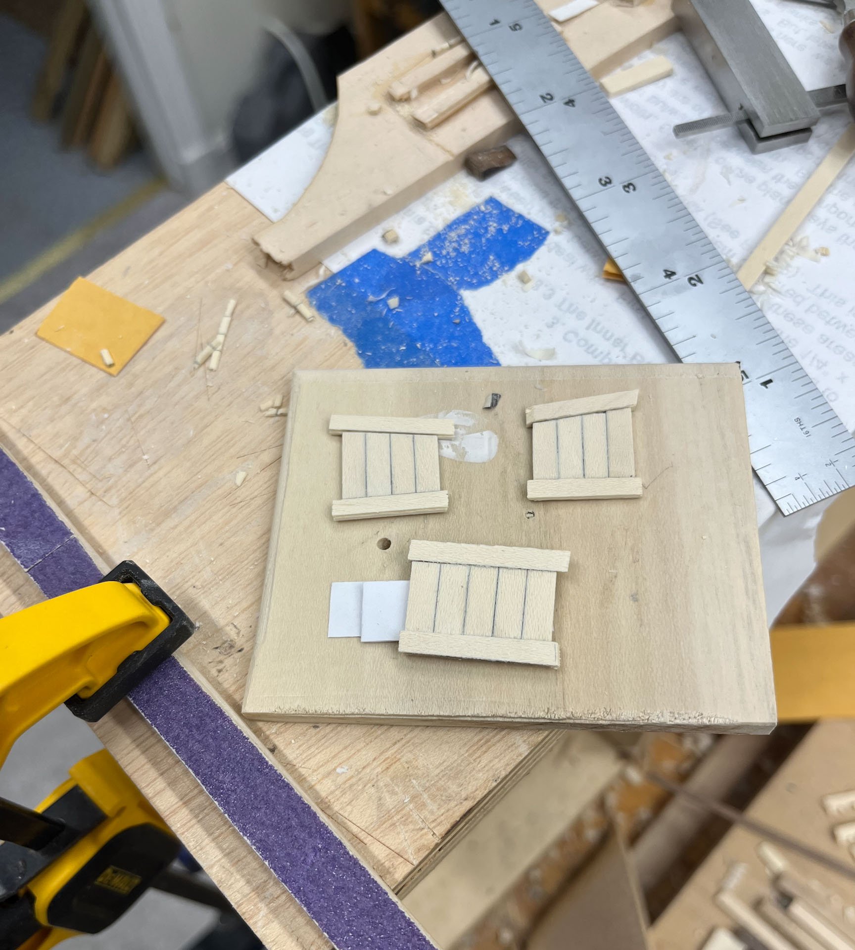
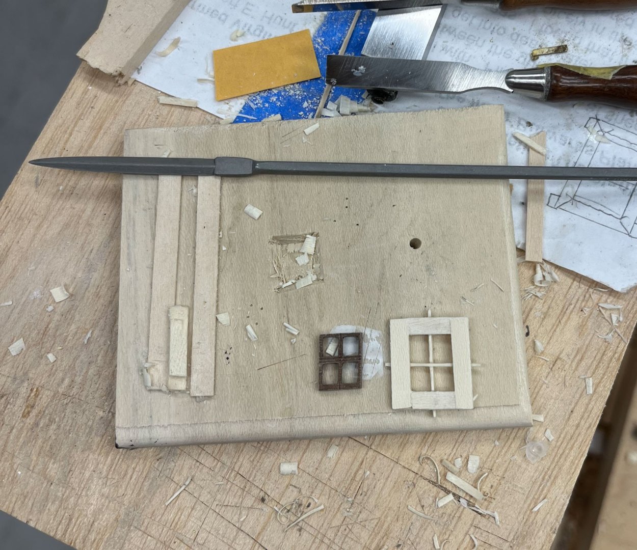
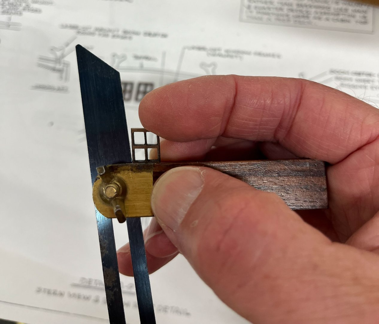
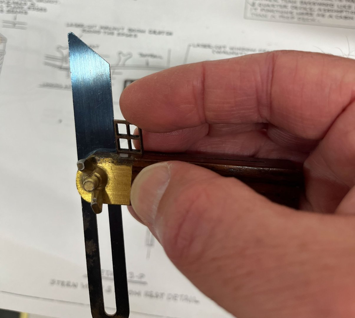
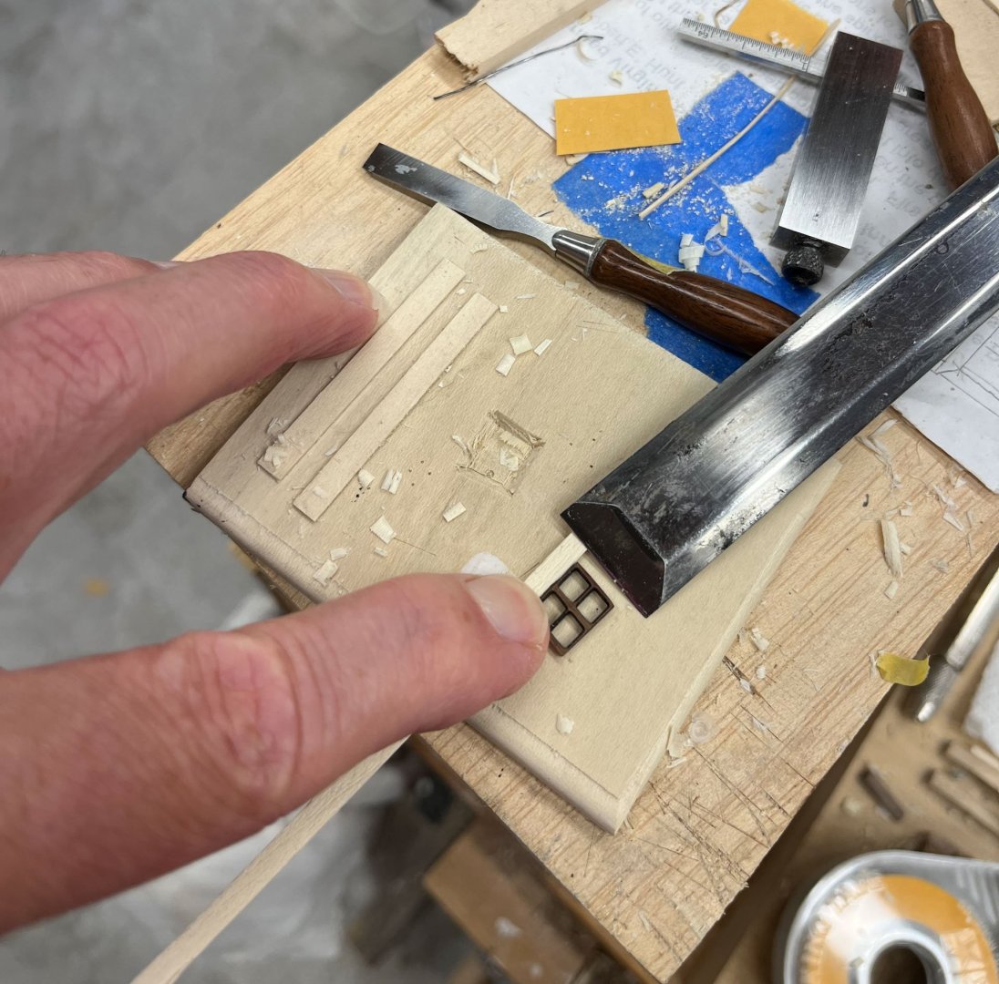
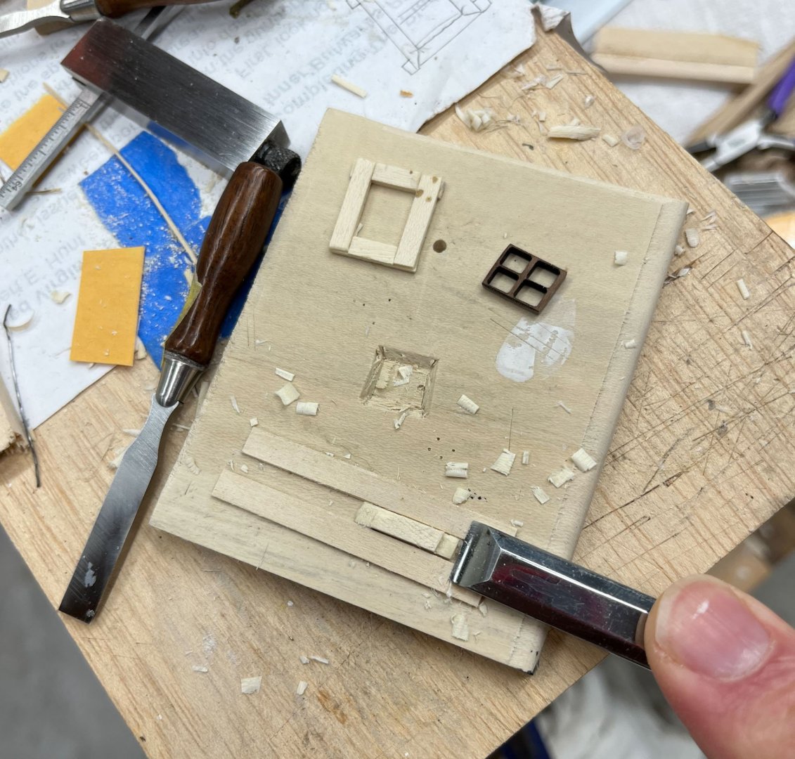
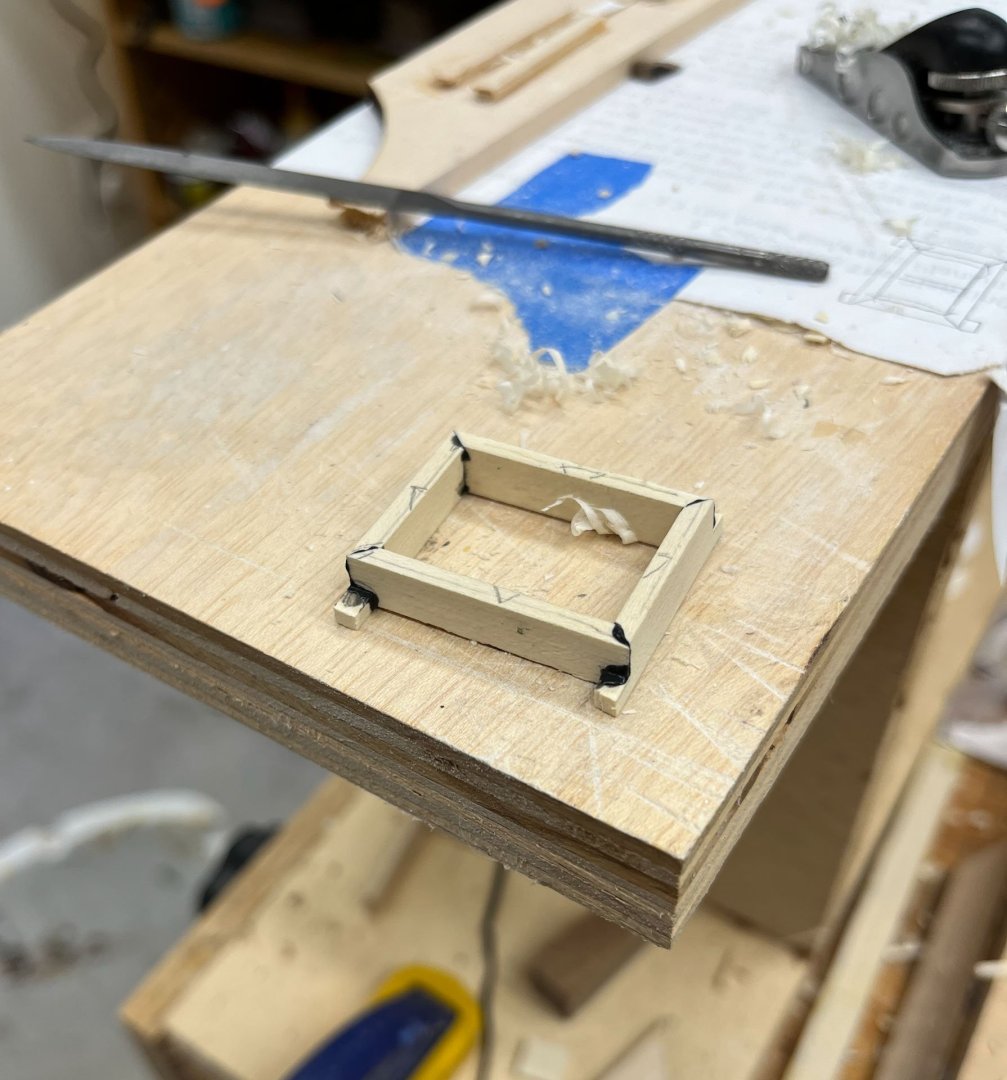
Happy Saturday MSW! Today I will document the start of my attempts to make Windows. The AVS comes with laser cut windows in walnut which are actually pretty good. I decided to start my window construction by copying one of them. There are 4 windows spread in an arc across the stern, 2 on each side. As I had suspected before the laser cut windows were made at 2 different angles; the inner windows are more angled than the outer: Inner Window: Outer window: Each side is of course a mirror image of the other; thats 4 different windows that are similar enough there is no way I won't end up making some of them backwards, upside down, etc. I followed David Antscherl's basic construction techniques from Swan? or possibly Speedwell. Anyway his method was my inspiration. As usual I am making everything from holly, and since I don't have any milling machines its all by hand. I decided to make it a little easier on myself and build an overscale window to practice first. It is Really Challenging holding these tiny pieces of wood steady. Almost as bad as the ring hardware. So my first thought was build a practice version a bit bigger than the final to work out my technique. I think it was a good plan, and overall I felt using the biggest piece of wood for each part I could helped holding and manipulating. Then trim to size later. To get my window angles I used one of the lasercut kit windows (an outer one) to guide my chisel. A gentle score was all thats needed, then the chisel blade slips naturally into the score mark and is easy to deepen. I used half-lap joints to form the oversize window frame. As per David I glued down 2 strips of wood that were 1/2 the thickness of the window frame parts and used my chisel to Gently pare the half laps to size. The only way I could hold these little parts is with my fingers and I was cutting Towards said digits so I went very careful. Sharp is essential and pares away little slivers of wood nicely. Dull blades jump and and skip and go where you didn't plan. This time there was no blood. Once the frame was dry (and I had to recut one side as I made the original part the mirror image of what it should be) I tackled putting in the grill, clearly the trickiest part. I lightly scored the frame with the same wide chisel used above and gently pared out the grill mortises using a combination of chisels, a very fine hobby saw, and some fine vallorbe files. I fitted the rail first which took several episodes of thinning with the veritas miniplane. The rail is 2/64" thick if anyone was wondering. And then the really hard part, fitting the muntin. This involved cutting a half lap joint in both the sash and the muntin so the grill parts end up level with each other. Everything was done with the optivisor. I put a thin piece of wood under the rail so it wouldn't deflect then scored Very Gently with my chisel and cut out the mortise. And here is the muntin in place. The grill is inset into the window frame which is what I wanted, and not flush with the outside of the frame. I really feel that having some reveals looks more authentic even though it always means more exacting work. Since this is a practice round I will leave this window as is but if it had been a final version I would let the grill dry and then sand the frame down to its final width. Heres the window laid on the AVS stern and while the frame is obviously too large I think the grill looks more in scale than the kit version. Anyway I dont think I can make the grill any smaller so thats what I'm working with. If I was Really Crazy I would try to scrape moldings onto the grill and inner window frames instead of leaving them as simple rectangles. But at present I am Not That Crazy and I think holly is too soft for that kind of detail. One thing I discovered is my 12 pack of Vallorbe Escapement files 4 cut (super fine) doesn't have a single rectangular file. There are 2 rounds and 10 curved, half round, triangular, but no rectangular one that would have fit nicely into these tiny mortises so I am off to OttoFrei.com. Legitimate (as in I actually need it) tool purchase ahead. Next up is figuring how I am going to mount the windows. As it is right now the window frames don't have anything to keep them from falling into the stern gallery so I am thinking about gluing some backing strips for the windows to push up against. But first I have to figure out exactly how thick the windows will be, what about glass, what about an exterior frame, etc, so some deep thinking ahead. Stay tuned. thanks for reading Cisco


-
nice repair!
-
thats exactly how i fix wonky bulkheads too. looks great
-
Those are some nice close-up shots BE. Looks just as good micro as macro.
- 131 replies
-
- 1
-

-
- Medway Longboat
- Syren Ship Model Company
- (and 1 more)
-
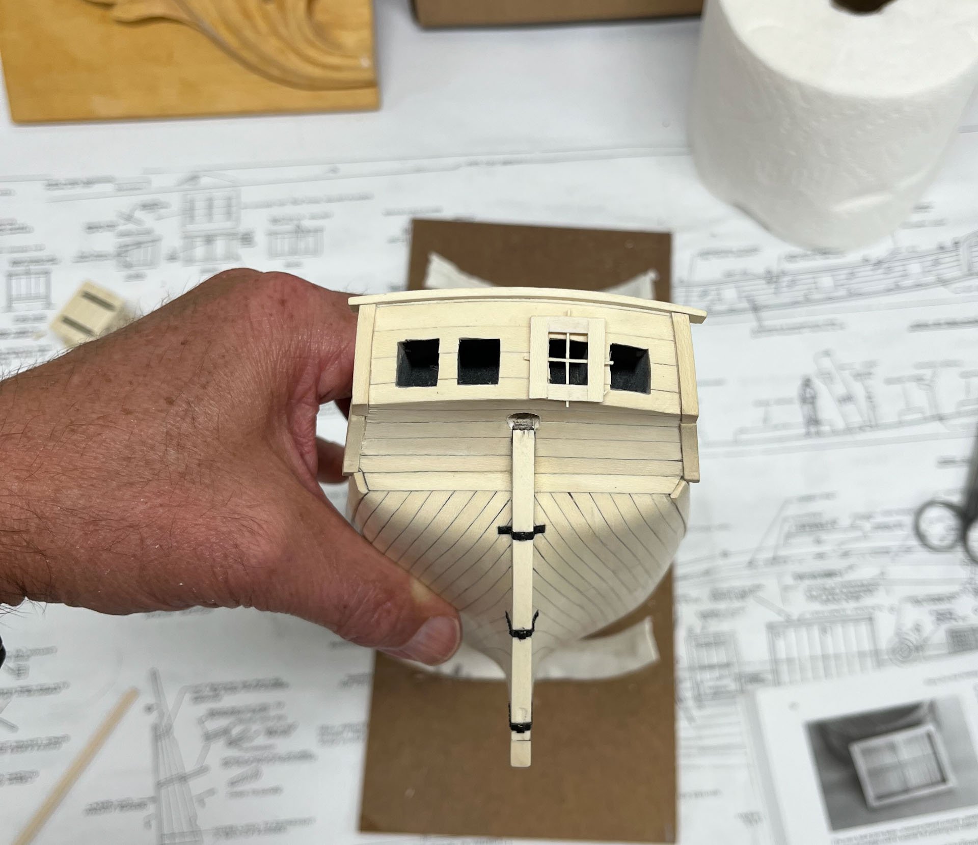
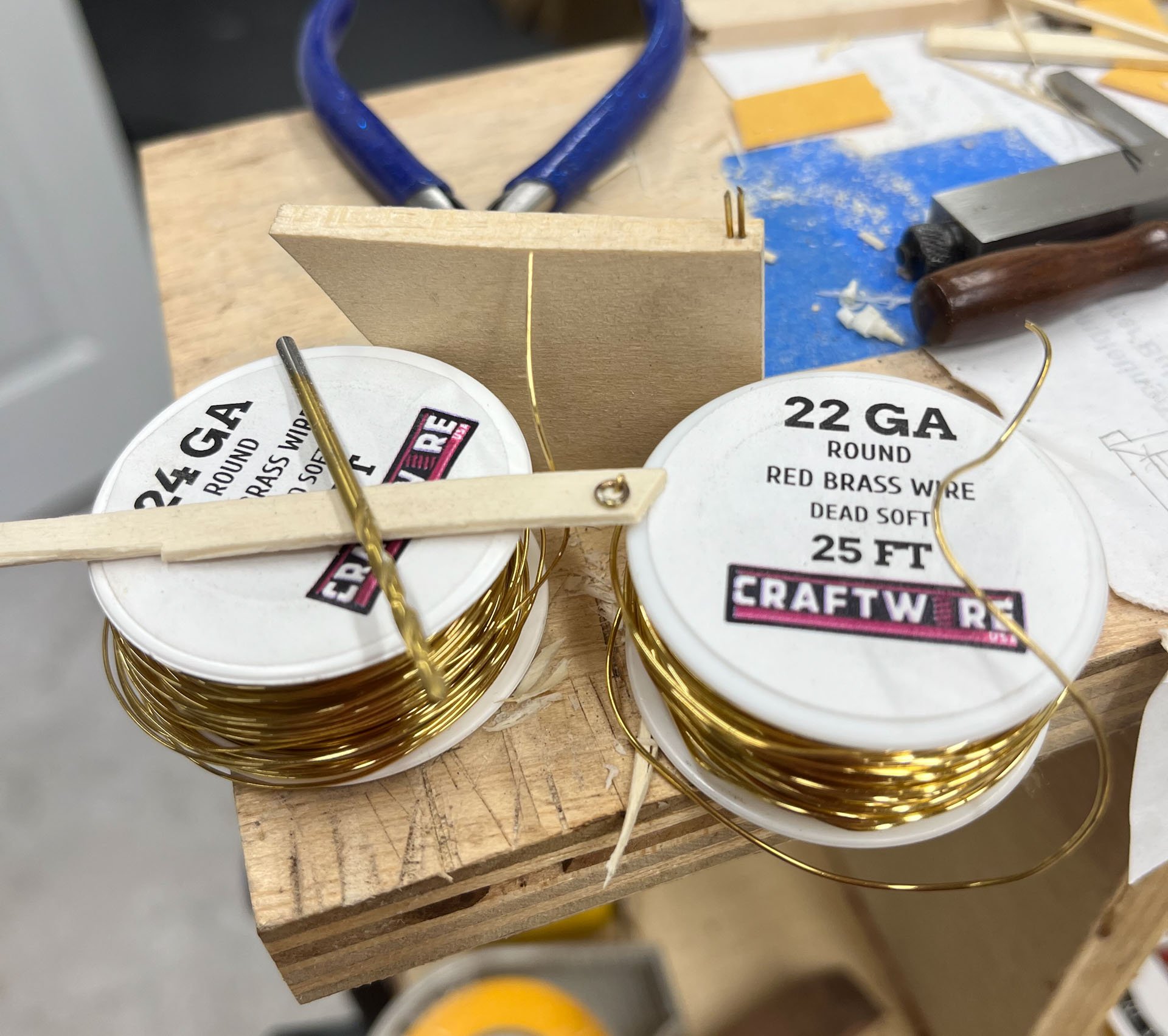
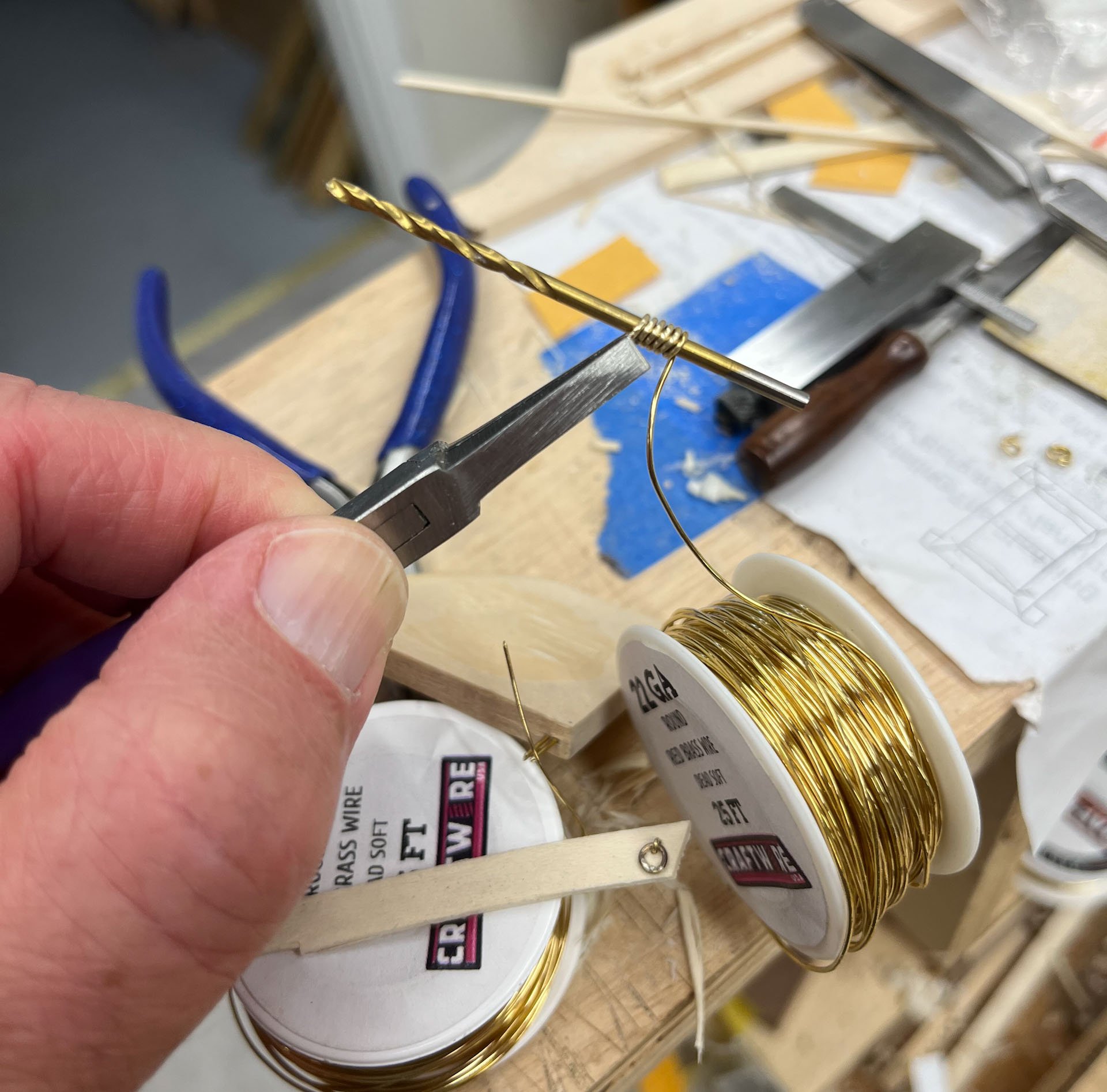
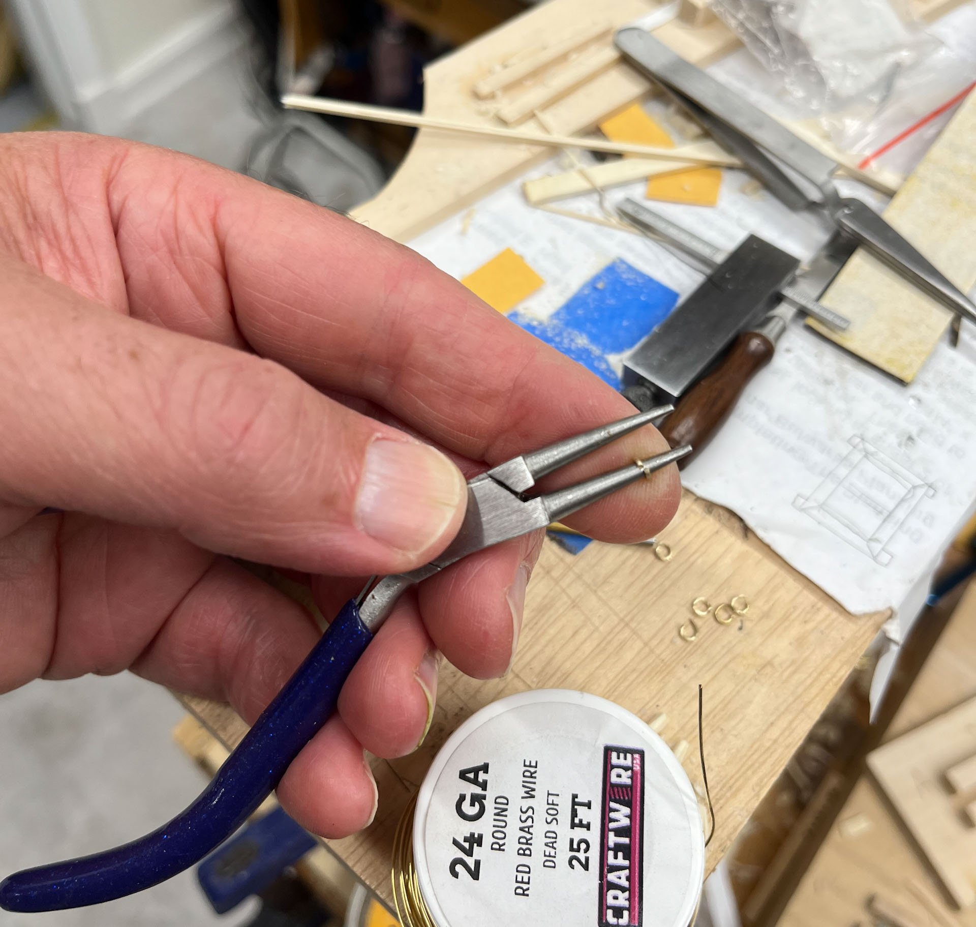
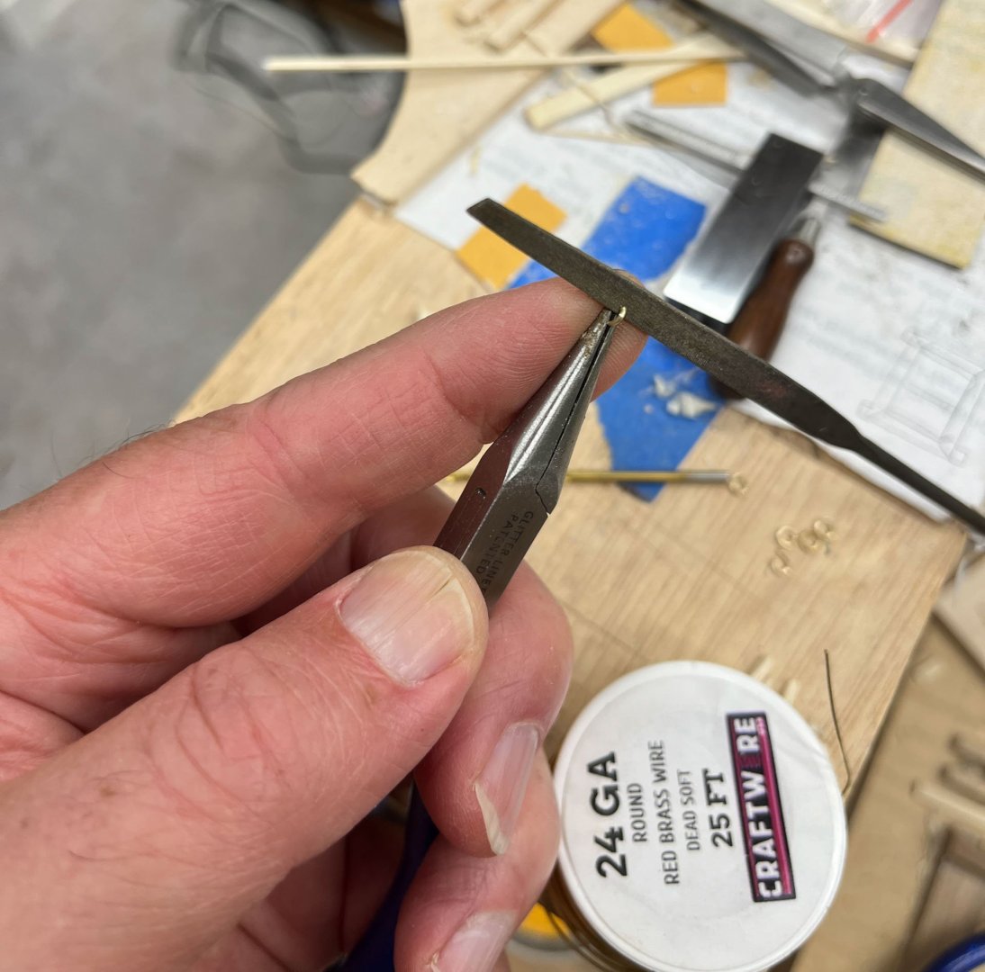
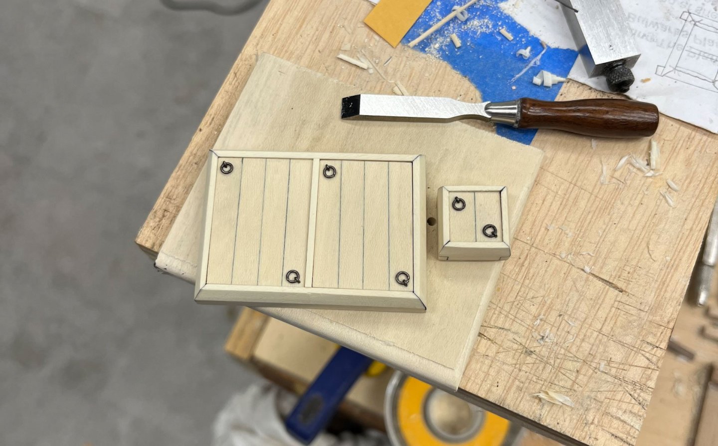
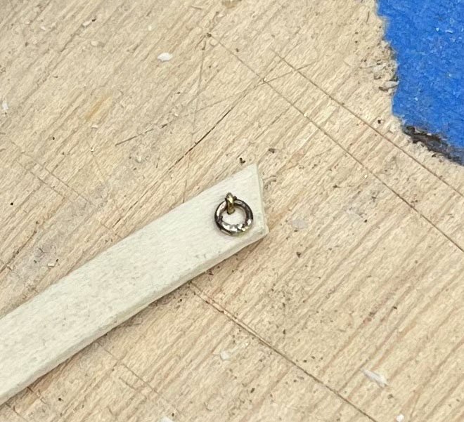
Happy Labor Day to all you who celebrate it! Weather here in Delaware was perfect for the pool, and my kids start back to school tomorrow, oh happy day for us parents. Thank you guys for all the likes, I appreciate it. Hamilton I'm following your build closely, Ronald as well, BE your longboat is beautiful, and Aliluke welcome back from vacation. Trying to up my game to stay on pace with you guys is motivating. Shorter post today covering how I made the ring hardware. I've never done it before so this was all new to me. Lots of people have posted their methods and I mostly copied appropriately. First up I did a test ring on some scrap, instead of on my finished panels like last time. I had read the ring was usually thicker than the staple holding it in place so I used a different brass wire for each. Experience has taught me that drilling holes by eye usually ends up not working so I also wanted to make jig to standardize the staple holes. Here's my test ring, I think it looks good. The above ring was silver soldered but I didn't solder any of the other rings. The solder made one side look thicker and my files wouldn't easily fit inside to even it out. The below pic has all my parts. At the top is a piece of scrap wood with 2 of the smallest brass nails I have inserted into 1 end and the heads clipped off. I filed the ends a bit pointier and squeezed them together until their width looked good. I used a 5/64" drill bit (the 3/32" was a little too wide) to form the rings from 22g wire, and made the staples from 24g wire. The spools of brass wire are from Amazon. I wound the brass wire around the drill bit and pulled the coils tight with my mini-pliers. I cut the links with a pair of mini wire cutters. I had read of others using a hack saw or small saw blade but I don't have anything that tiny. The down side of the wire cutters is it left squished ends of wire that don't come together flat. So my next step was holding each link in my mini pliers braced against my finger and using a dedicated file (I use for brass only) to flatten each side. Then I re-formed each ring on the jewelers round nosed pliers which ensures the rings end up round. As an aside I got all the tools at Micheals in the bead jewelry section. It would have been impossible to do most of this work without these tools. And here is the final result after blackening. Manipulating the staples led to some of the blackening wearing off so I will touch up with some black paint before final installation. The close-ups are merciless (i can see some imperfect ring joins but I'm going to live with it). The staple's smaller gauge wire contrasts nicely against the thicker rings more than I thought it would; definitely don’t make them the same size wire. Next up, instead of more deck furniture as I said last post, will be the stern windows. I put off doing them in the past because I was worried about damage during future handling but now seems to be the right time. I'll have to flip the hull about to measure and fit the windows and more and more breakable inventory will be added to the upper deck from here on out. Thanks for reading Cisco


-
i did not fully realize how much work a single Shrouds entails; it looks pro to my eyes. are you using the kit line or Syren thread?
-
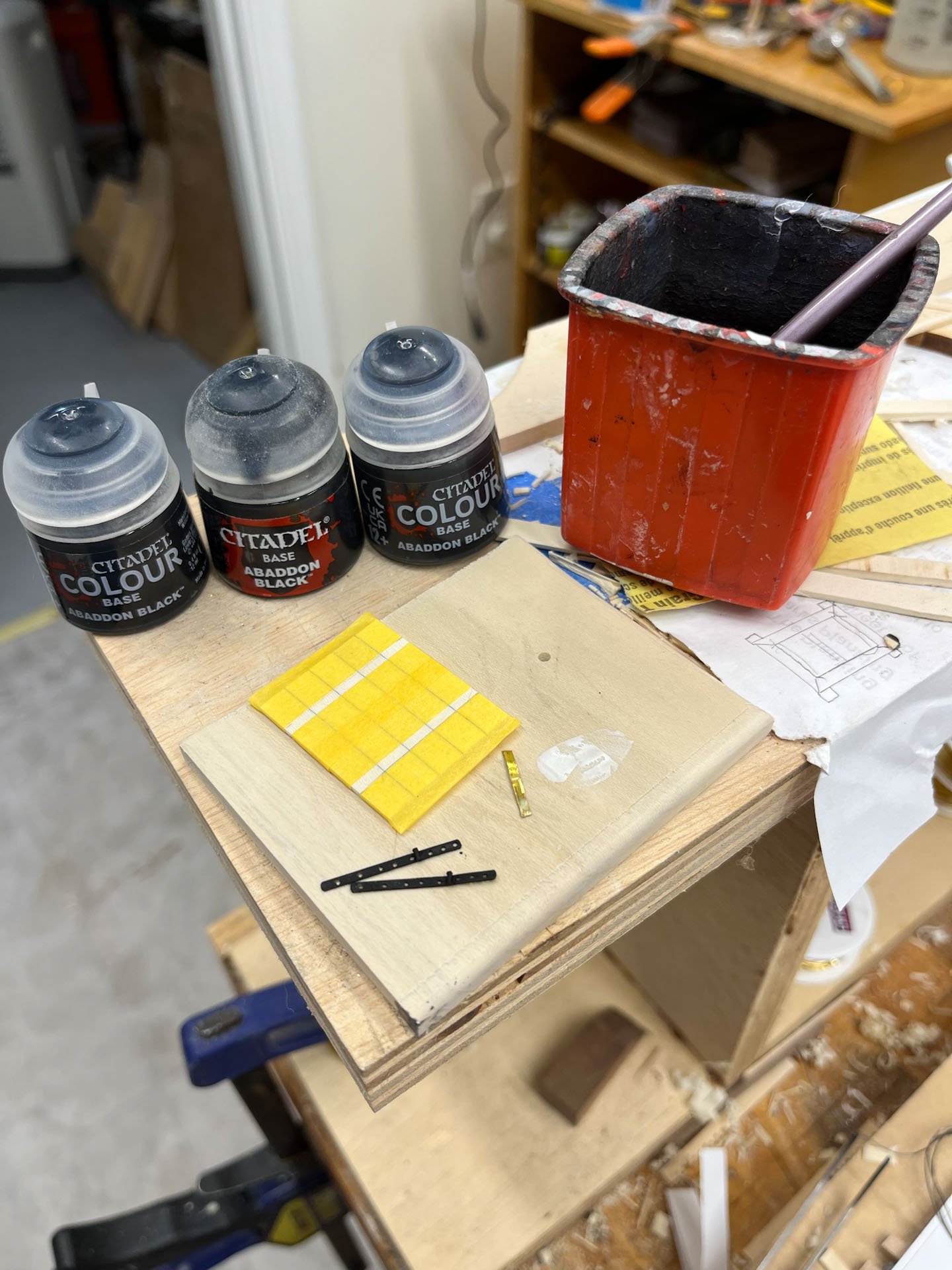
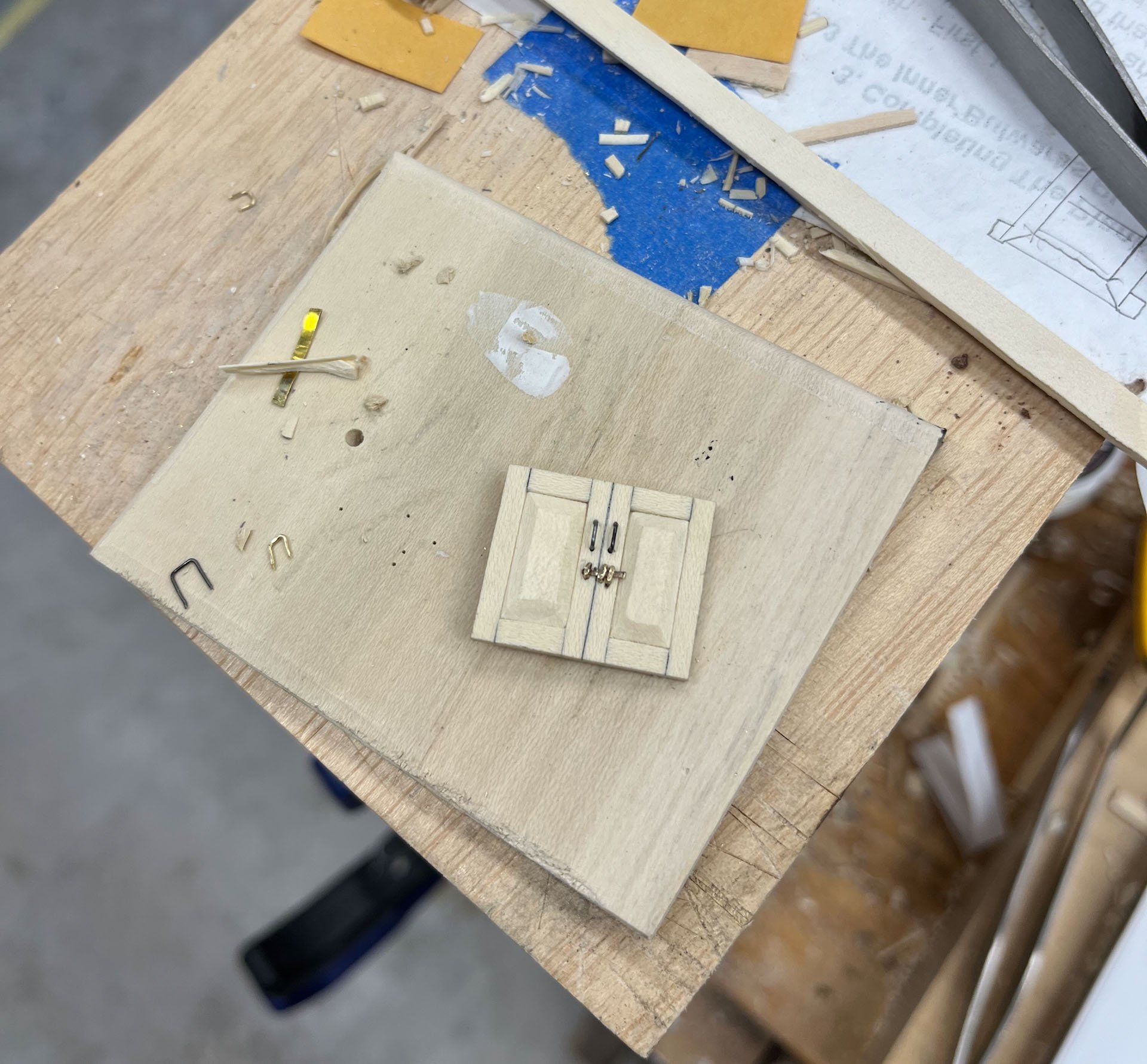
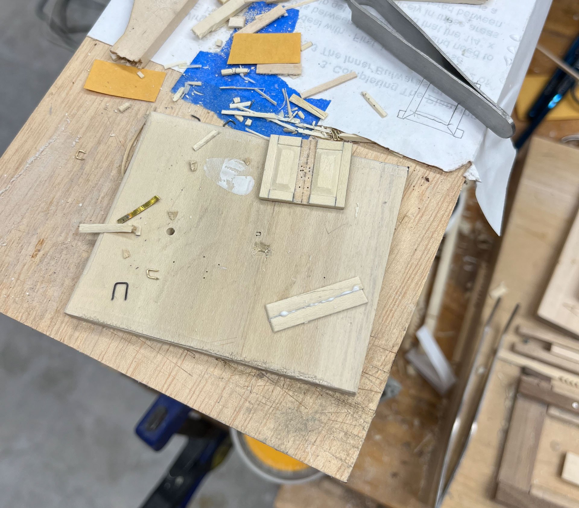
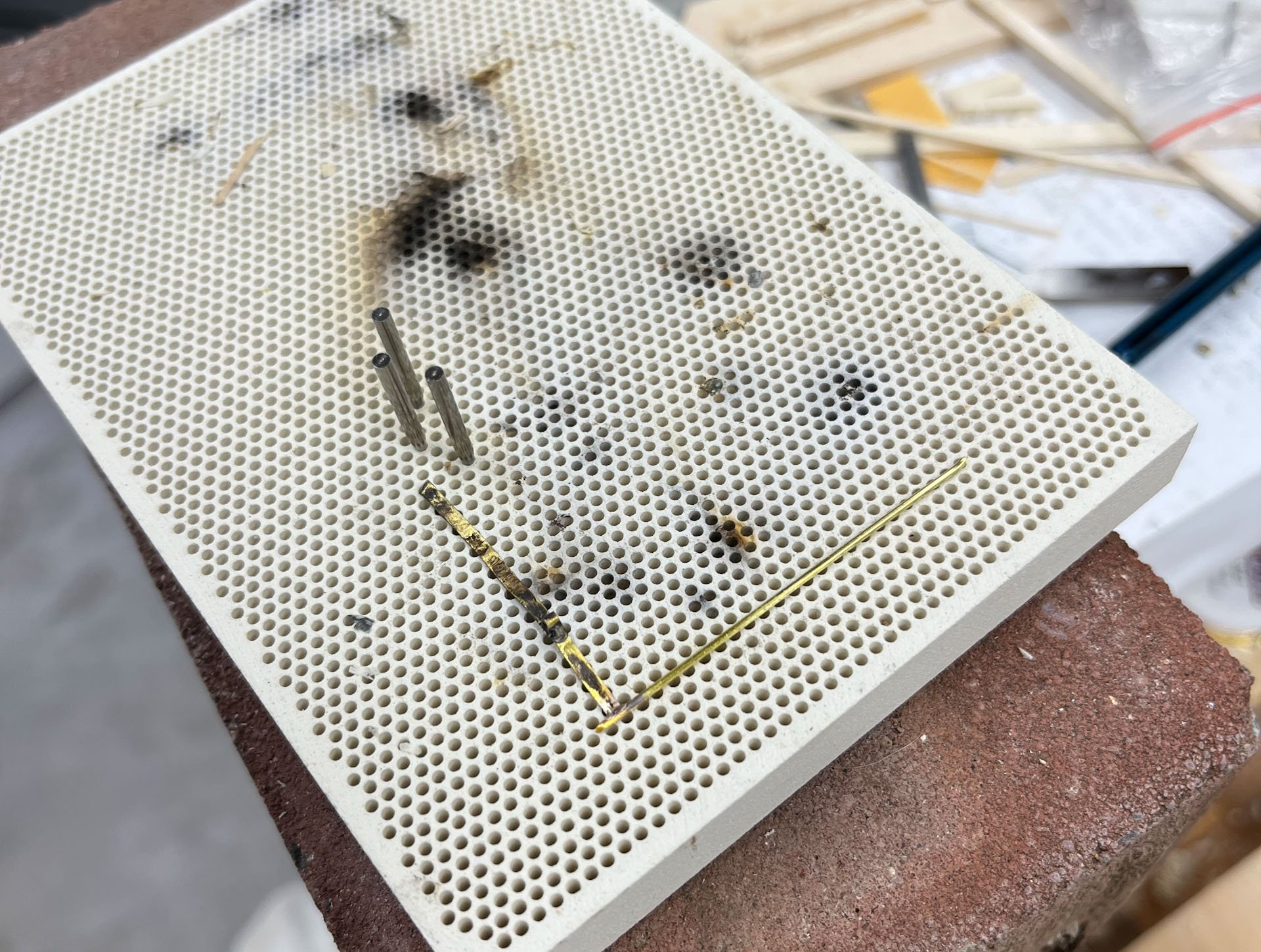
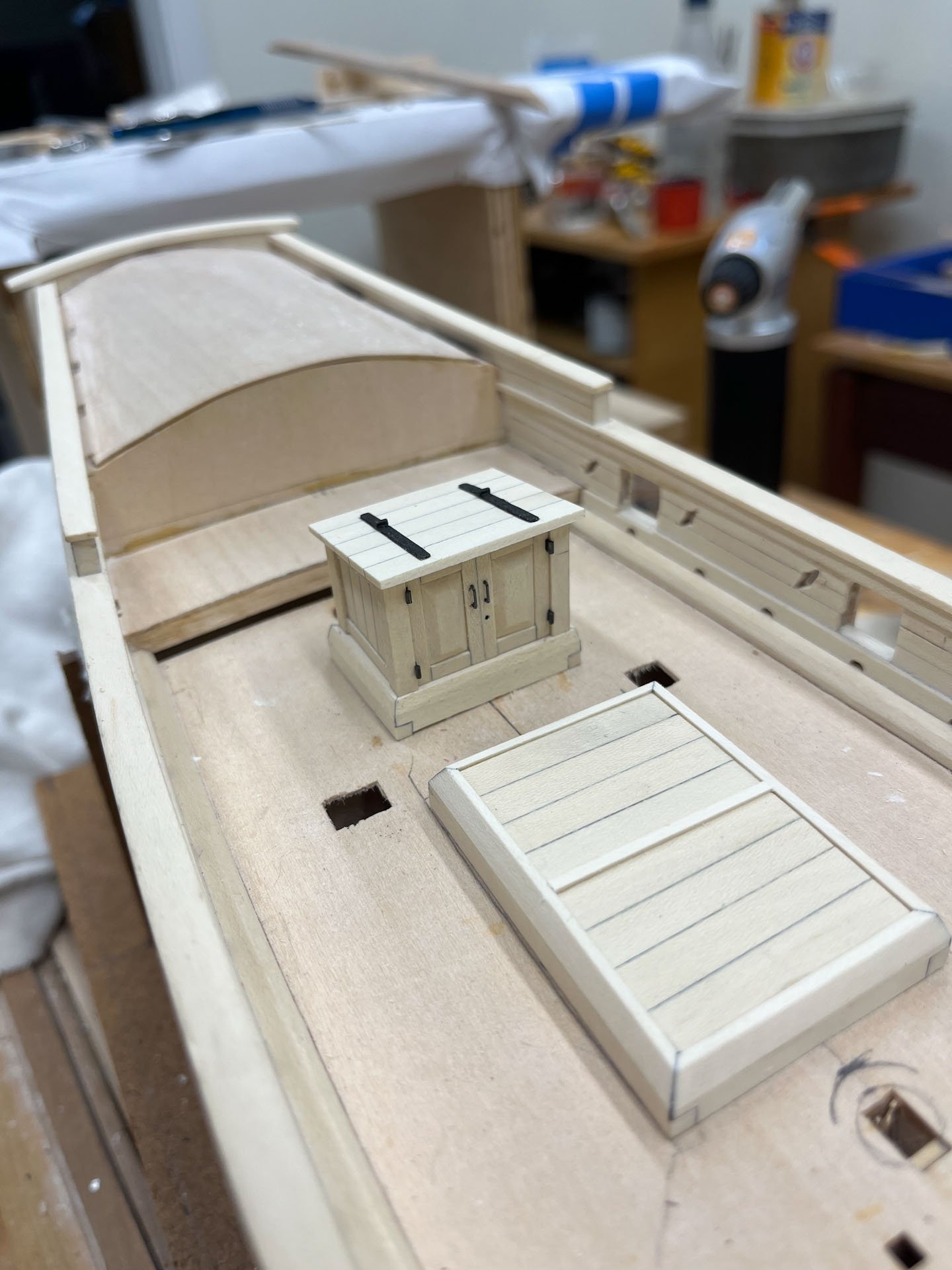
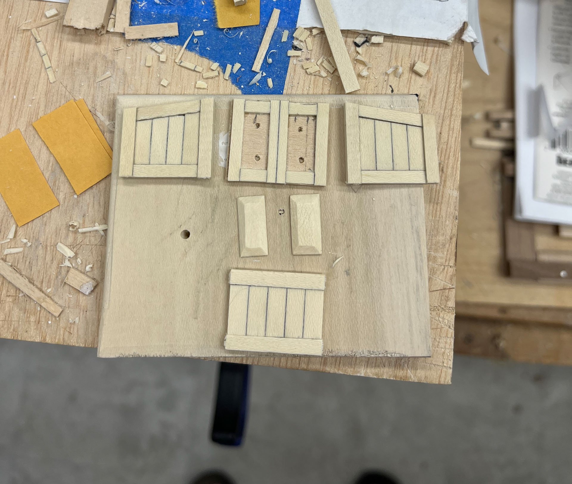
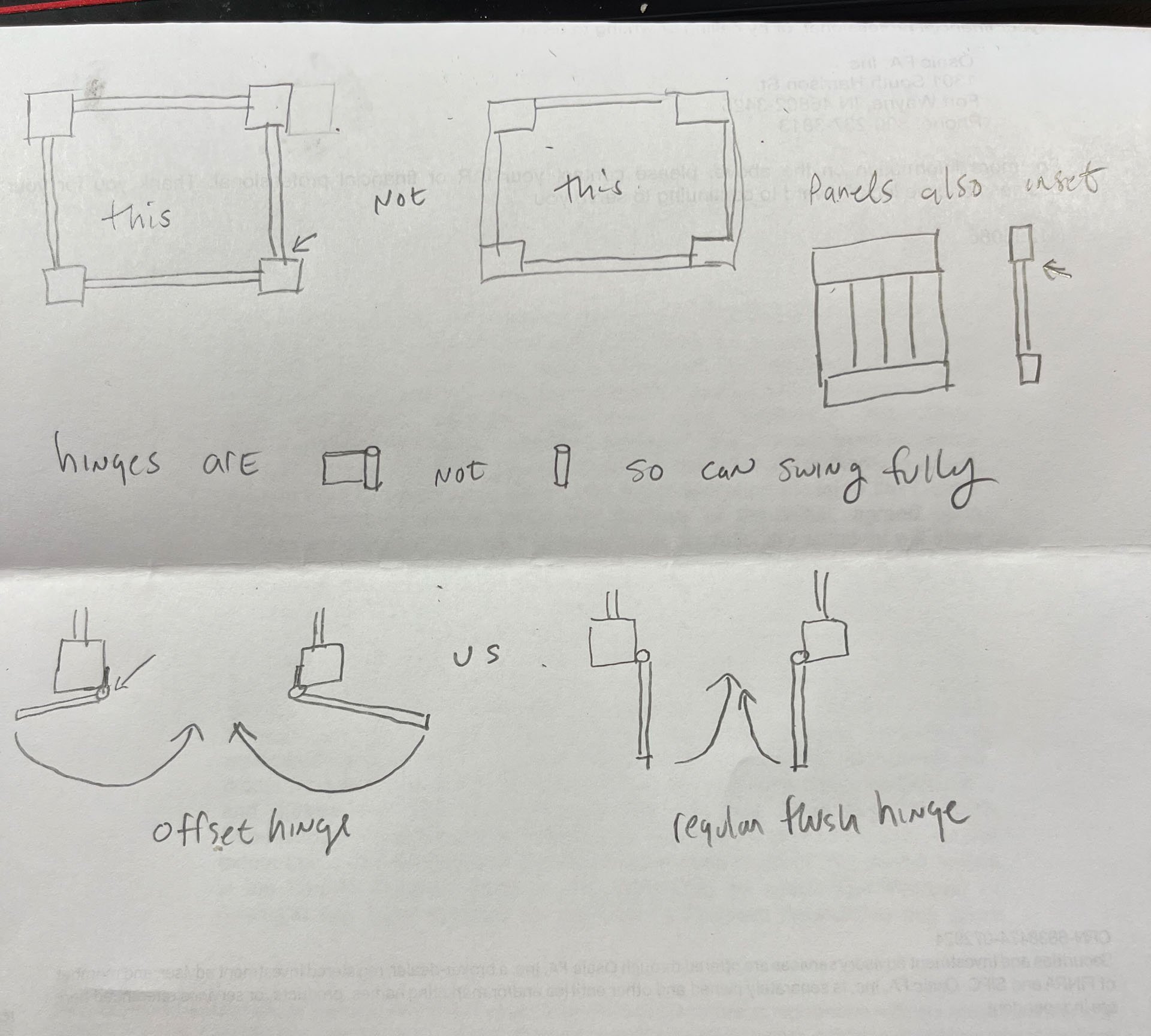
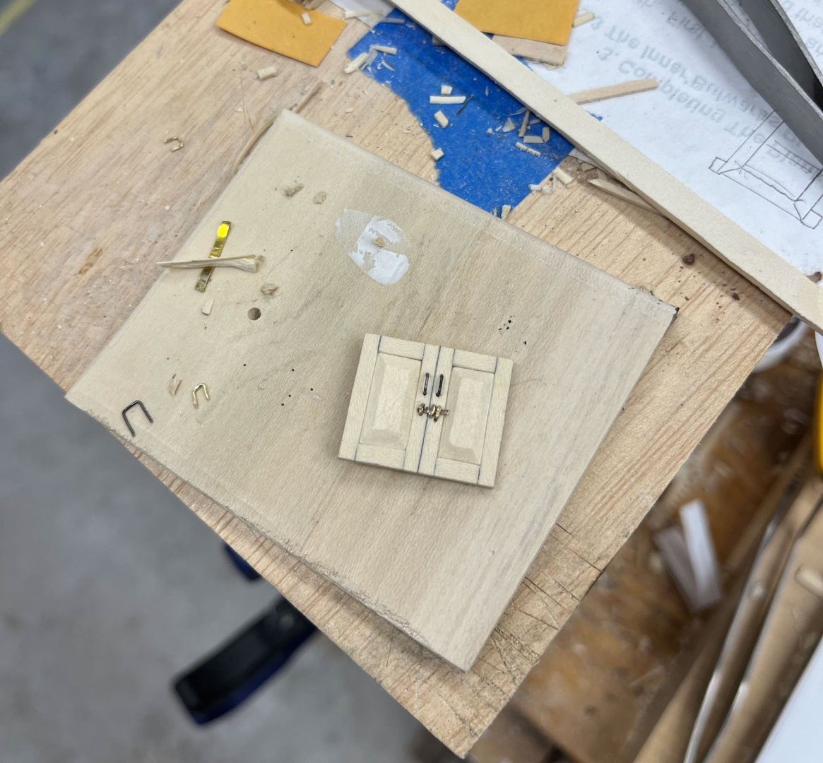
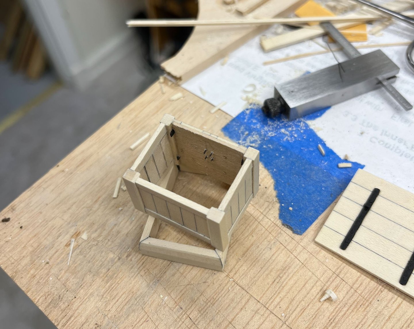
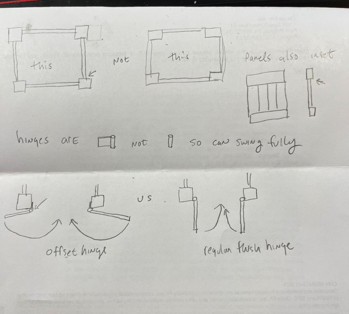
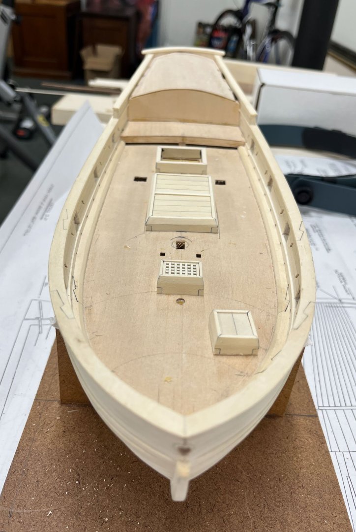
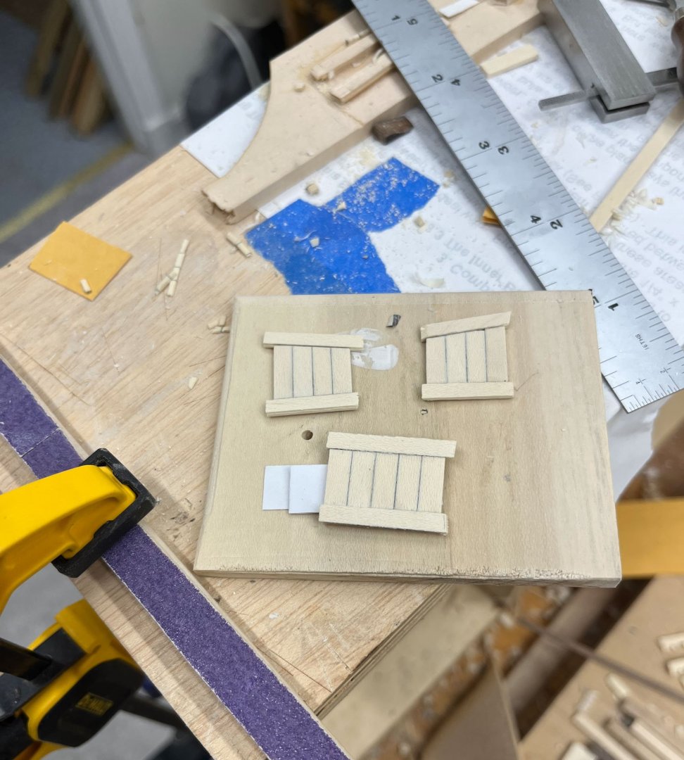
Good Thursday evening MSW folk. Today's post is devoted to the Companionway which was a lot harder to make than I anticipated. I built the coaming in my last post; this was the same as all the other coamings with mitered half-lap joints. I wanted to build my companionway with annoyingly cool details that came back to haunt me. Below is my cartoon explaining My Big Plan. First off for visual interest I wanted all the panels to have a small setback from the corner posts; I didn't want them flush. Thats demonstrated in the plan views at the top. This adds subtle shadow lines which in theory better define details. Then I had to figure out the hinges. If the front doors are inset you can't use regular hinges because the doors will only open 90 degrees; but with offset hinges where the hinge part is outside the corner post the doors can open much wider- see the lower part of the cartoon for a better visual explanation. In reality the offset hinge would have another bent part connecting to the door which my cartoon doesn't show well but I didn't feel like redrawing it. The raised panels were straighforward. I made the front door panels by gluing stiles and rails to a thin piece of wood that came with the kit. Then I sanded the panels to fit and used chisels to cut the raised portions. Next time I will be more careful marking but I feel these were good enough. I drilled holes behind the panels so I could stick wire through to pop the panels out - they were a snug fit. Then I tried to make the hardware. I had a mental image of a wire handles and a sliding latch-lock contraption. I should have tested the latch idea on scrap first; it didn't work at all. I couldn't get the hardware pieces small enough and this was the result: You can also see my handles weren't well aligned. So I carefully chiseled the middle 2 pieces out, glued up new ones (drying at the bottom of the below pic), sanded them until I got a snug fit and glued them in. I call it a good repair; I couldn't tell I did it afterwards. I re-drilled the handle holes being more careful to make them even and left the latch off. I poked a hole under the handles with a nail and put a drop of black paint in to represent a keyhole. Sometimes simpler is better and this looked a lot better to my eye. Next up was making the offset hinges. I silver soldered some brass rod to brass strip, filed the pieces flush, blackened them with Brass Black very diluted, and inserted them into their holes along the side of the doors. Here's a shot of the interior of the companionway. I found it easiest to drill holes all the way through the door for the handles, and filed small slots for the hinges. This made it easier to adjust how much they stuck out. Later I blobbed some epoxy on the inside so the hardware would stay put. Next up I made the roof, fairly sraightforward. I learned my lesson about glue splash and covered the panel entirely with Tamiya tape except where the hinges would go. I used epoxy to hold the hinges in place, afterwards drilled holes for bolts and sanded them fairly flush. And finally I painted them black. Looking into my paint box I found I had purchased 3 separate bottles of black paint, go figure. And finally I put it all together. I think the pumps and binnacle are next. And I still have some ring hardware for the other hatches to make. thanks for reading Cisco


-
Planking Method Name
CiscoH replied to Thukydides's topic in Building, Framing, Planking and plating a ships hull and deck
i have been calling that a simple scarf joint, but so far have only used them on the waterway and the main rail of my AVS. interesting to find out if they have an official name when part of the hull planking. -
unrolling your paper template made it a lot clearer for me to understand. not a smooth wraparound but a changing radius curve. i begin to get why its so difficult
-
apologies if i missed it. what process do you use for blackening?
-
thats some nice planking. the finish elevates it to the next level
-
i love the expressivity of the tiny people - you can read their dismay!
-
pre-ordered, a new book from David is always worth the wait
-
beautiful work!
-
Mike thank you the perfect rundown on a milling machine. very helpful for those of us trying to figure out what to buy - there are too many choices!
- 969 replies
-
- 3
-
-
- hahn
- oliver cromwell
- (and 1 more)
-
you do high quality work Thukydides; I will follow with interest
-
Beautiful! I especially admire the painted stern and bulwarks. yes, so, whats next?
- 562 replies
-
- 3
-
-

-
- vanguard models
- alert
- (and 2 more)
-
nice even planking job Mugje
-
Its Sunday afternoon. Still hot and humid here but not as hot and humid as last week. Time for an update. tmj - I had considered a jig similar to your idea. But to make it I would probably need a tablesaw to accurately cut the frets. My understanding is some of the original modelers started with a square of wood and chiseled each grate hole out individually; this sounds even more crazy than my method. A bit up the page here Dan (Shipmodel) had recommended making the grating first and then fitting the coaming which is what I ended up doing, good advice thank you Dan. I started on the companionway coaming next. I built it the same as the others with mitered half lap joints; to make the joint lines stand out I again used #2 pencil graphite mixed with gorilla glue. I trimmed the horns and glue blobs next. Here is a shot of the deck with all the coamings in place (nothing is glued yet). I realized that somehow I had made my coamings taller than the plans show. I think I made the first coaming extra tall so I could later trim it to the correct height. And then forgot, and made all my future parts the same height as the first. It was fairly straightforward to reduce the main and small hatchways. I ended up leaving the grating hatchway its original excessive height. If it were my ship I would prefer the deck furniture with holes in it to be as high as possible, and I figured it would make it easier to attach a canvas cover/batten. As long as it doesn't interfere with the cannons. Now I'm working on the companionway proper. I glued the panels for the sides up using holly strip and pencil to show joints. Its hard to see but there is slight reveal between the framing and the vertical slats the thickness of 3 pieces of paper. Next up is making the companionway doors. The instructions and the Bob Hunt practicum show them to be simple frame and flat panels; obviously this is too simple and I need to complicate things. So I will be attempting raised panels in my next post. David Anstcherl has directions to make raised panels in one of his books but despite reading it multiple times I can't figure out what he did (Fireship Comet pg 60). In one of the Swan books Greg Herbert used sanding sticks. We'll see what works for me. Enjoy the rest of the weekend all, thanks for reading Cisco
-
Purchased Swan II and had no issues with the website. Mike I am assuming its a Seawatch guarantee that i can now build to the same level as Mr Antscherl
-
pretty genius methods of construction BE thanks for posting your continuing tuitorial
- 131 replies
-
- 1
-
-
- Medway Longboat
- Syren Ship Model Company
- (and 1 more)