
CiscoH
-
Posts
384 -
Joined
-
Last visited
Content Type
Profiles
Forums
Gallery
Events
Everything posted by CiscoH
-
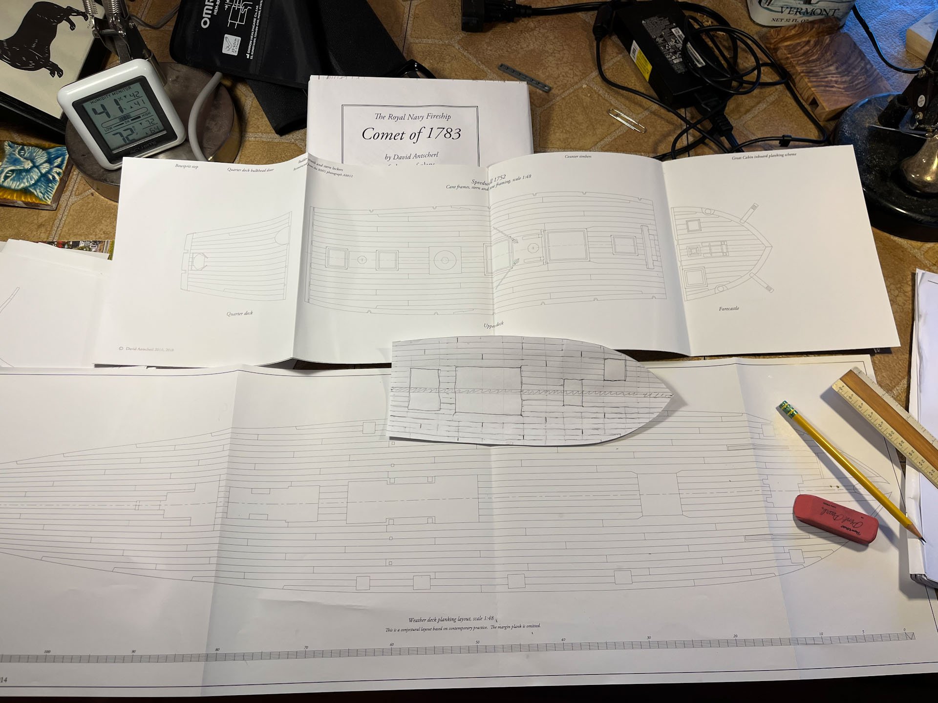
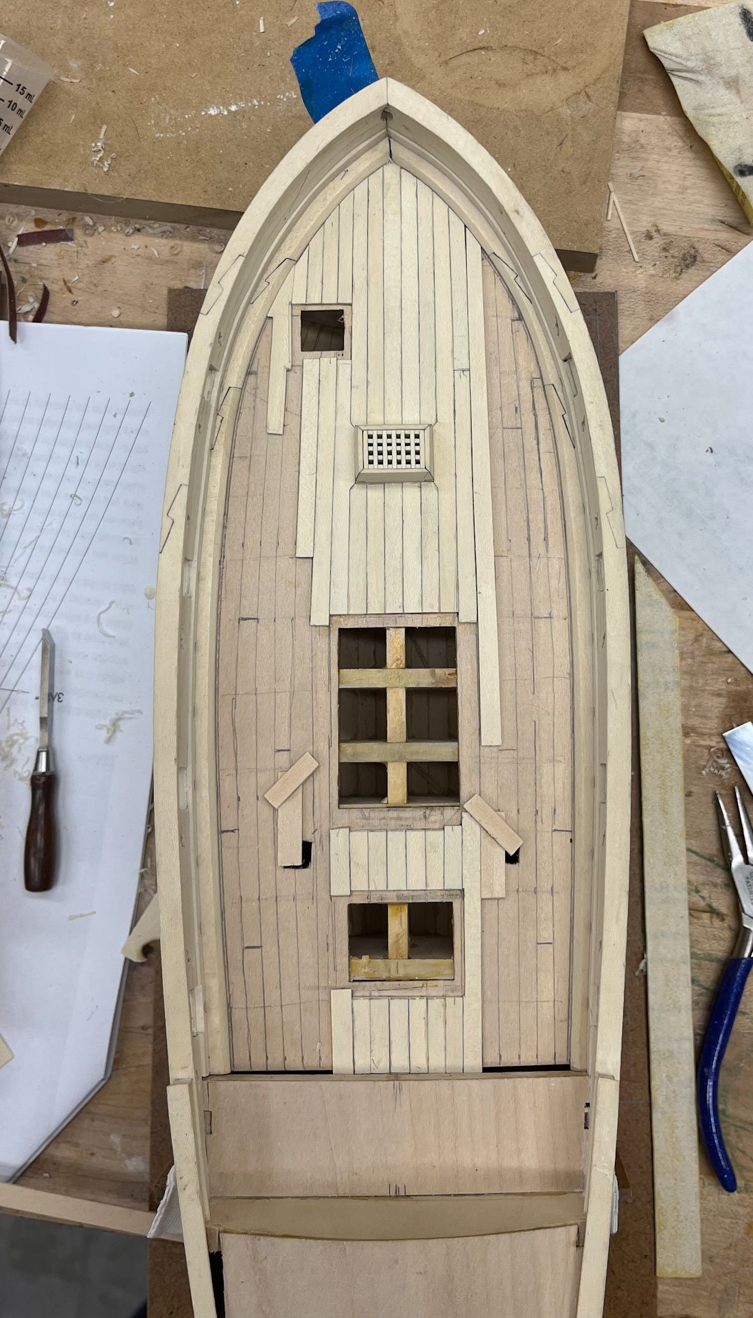
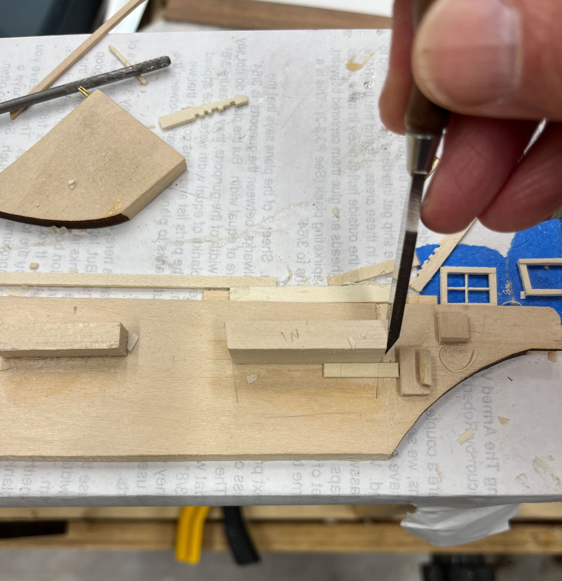
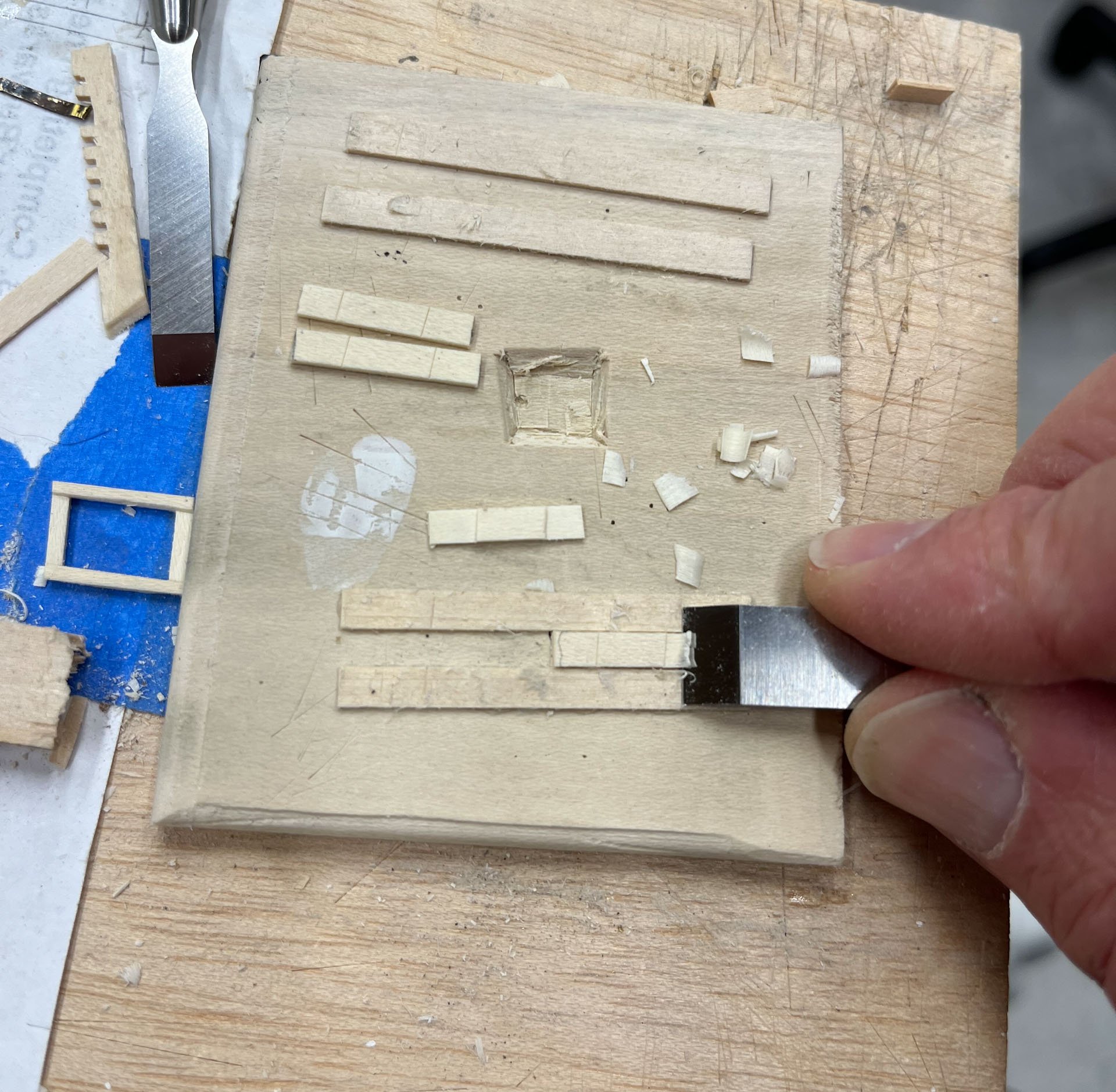
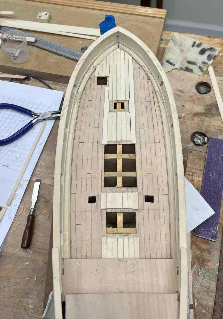
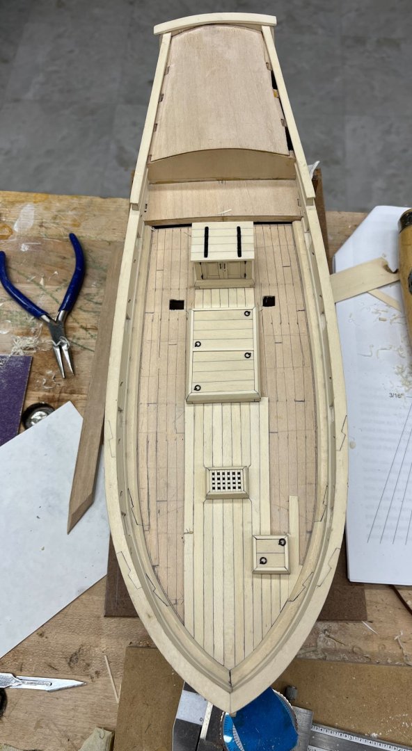
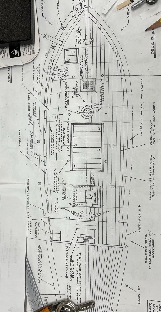
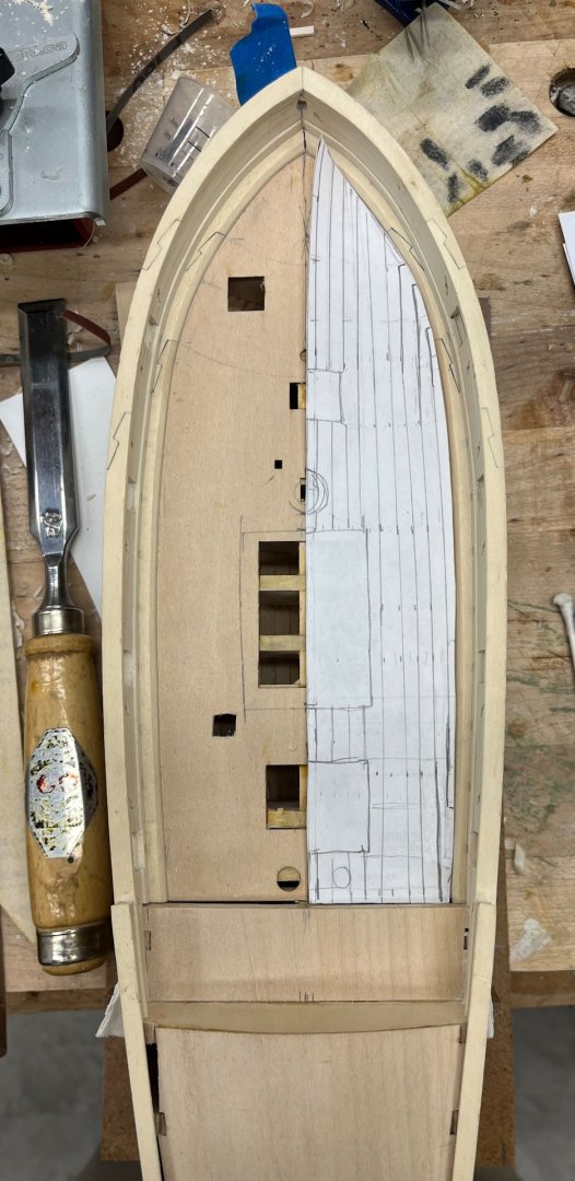
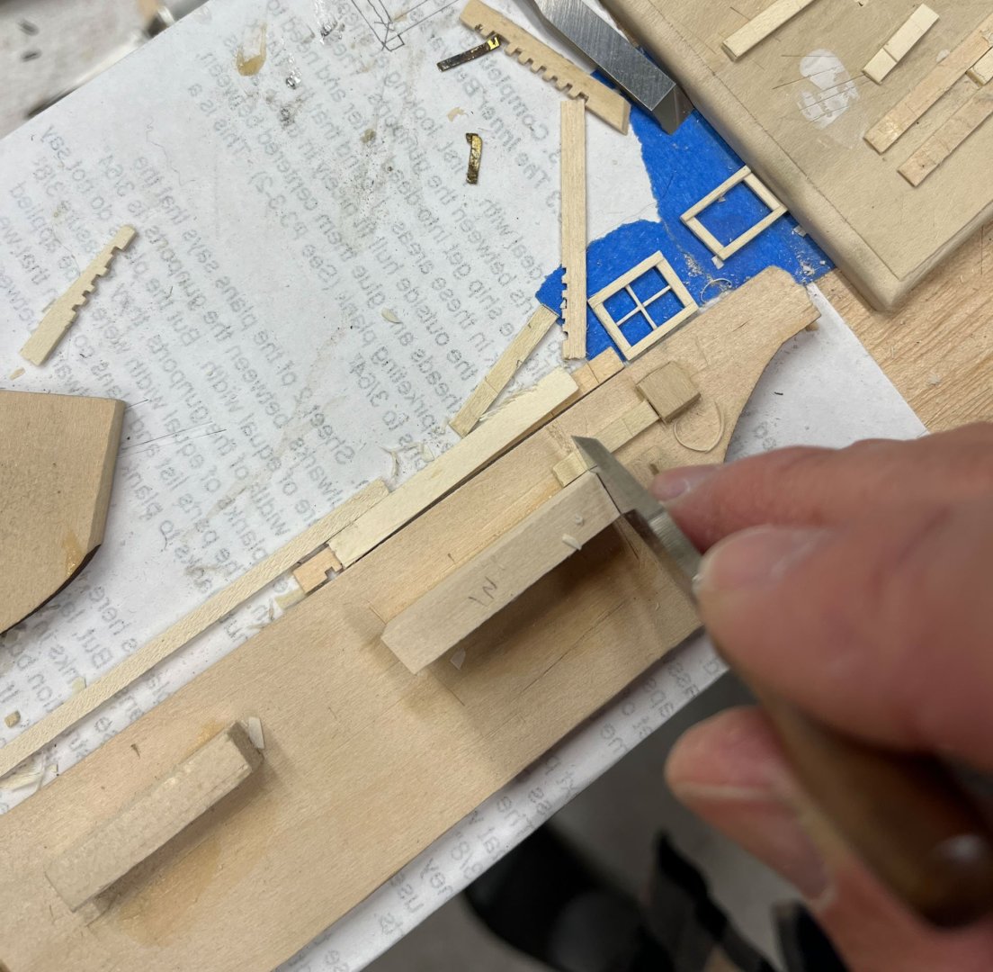
 Tonight is another mid-flight deck planking update. I had thought I was done with the Thinking Part but Lo I was mistaken. I was still happy with the curved outside and straight inner planking run. Then I tried to figure out my butt shifts. The Model Shipways AVS plans don't have any butts, the easiest way to deal with them I guess. I measured my hull planking and the longest plank was 7", or a scale 28' long, and a 3-butt shift. So I decided on 7" long decking, no problems, but what about keeping the hooked scarfs from being too long and not having butts in awkward places? A lot harder than it first seemed. A week later, after studying Cheerful, Comet, and Speedwell's plans and a lot of erasing I settled on a) 4 shift pattern, and b) where this pattern would start. This first butt of course dictates where all the other joints will be and I didn't want odd 2 foot planks at the ends OR a joint right next to the various hatches. (As an aside, I have been thankful I purchased so many of David and Greg's books AND plans, even if I never end up building those specific ships. They have been vital in helping me think through so many different tasks like this one.) I also had to figure out how to integrate the planking with the hatches and coaming. The fore grate is surrounded by notched planks. Fitting the next outer plank so it slides into the notched areas took some slow repeat sanding and many fittings but went ok. The port side went fine as I could leave the front end long and trim it later; the starboard side had to be fitted to the notches AND into the curved waterway. Pictured is my second attempt- it was all too easy to oversand the pointy part and leave a gap like I did here. Third time worked out though. Also shown above is me using the wrong wood. Both outer planks (the short ones) in the middle section are basswood, which is very hard to see. I realized it last night and replaced them no problems. The colour is very close! Here is a pic of the deck with most of the furniture in place. The big central hatchway is not square, its more of a trapezoid. At the time I didn't want to remake those darn mitered half lap joints and as usual its come back to haunt me. You can see the hatch skews to port a little when lined up with the decking (its even at the back, which can't be seen in this photo). One of the upsides of the basswood planks mistake was the opportunity to replace it with a wider one to help compensate. The fore grating fits well so now I'm notching around the companionway (which is thankfully actually square) and the large hatchway as my next steps. I made some jigs to help with notching 45 degree joints (laying on the deck above) with more accuracy as I eyeballed it my first go around. Well thats it for today. Happy Holidays MSW! thanks for reading, Cisco
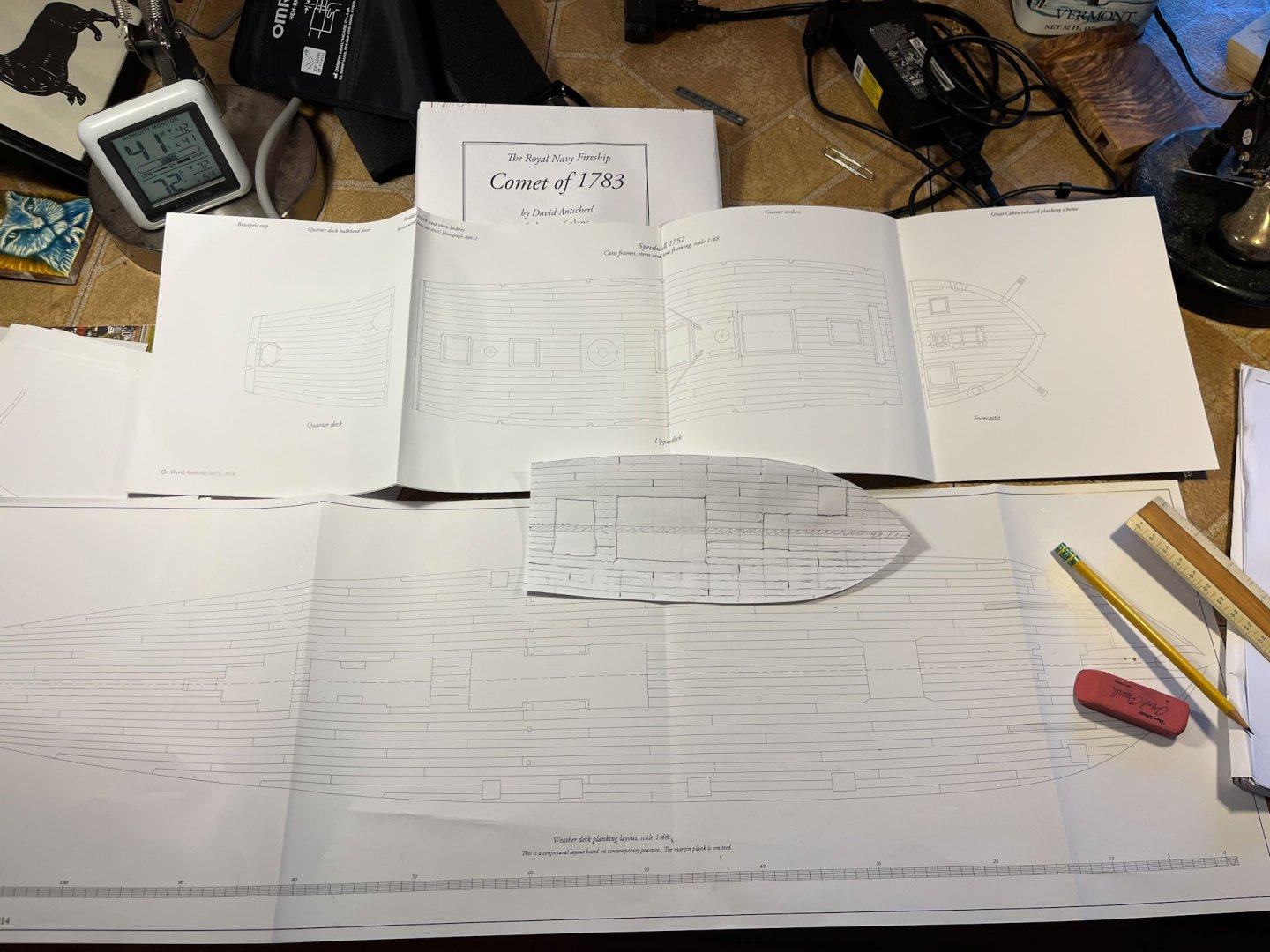

-
ancre La Salamandre by tadheus - 1:24
CiscoH replied to tadheus's topic in - Build logs for subjects built 1751 - 1800
welcome back Tadheus! -
great planking job. dividing the hull into sections with paper tic strips is how i’ve done it as well
- 141 replies
-
- 2
-

-

-
- Christiania
- Vanguard Models
- (and 1 more)
-
looks much better and you will thank yourself when you put on the stern planking. That Hump would have been very challenging to plank up to.
-
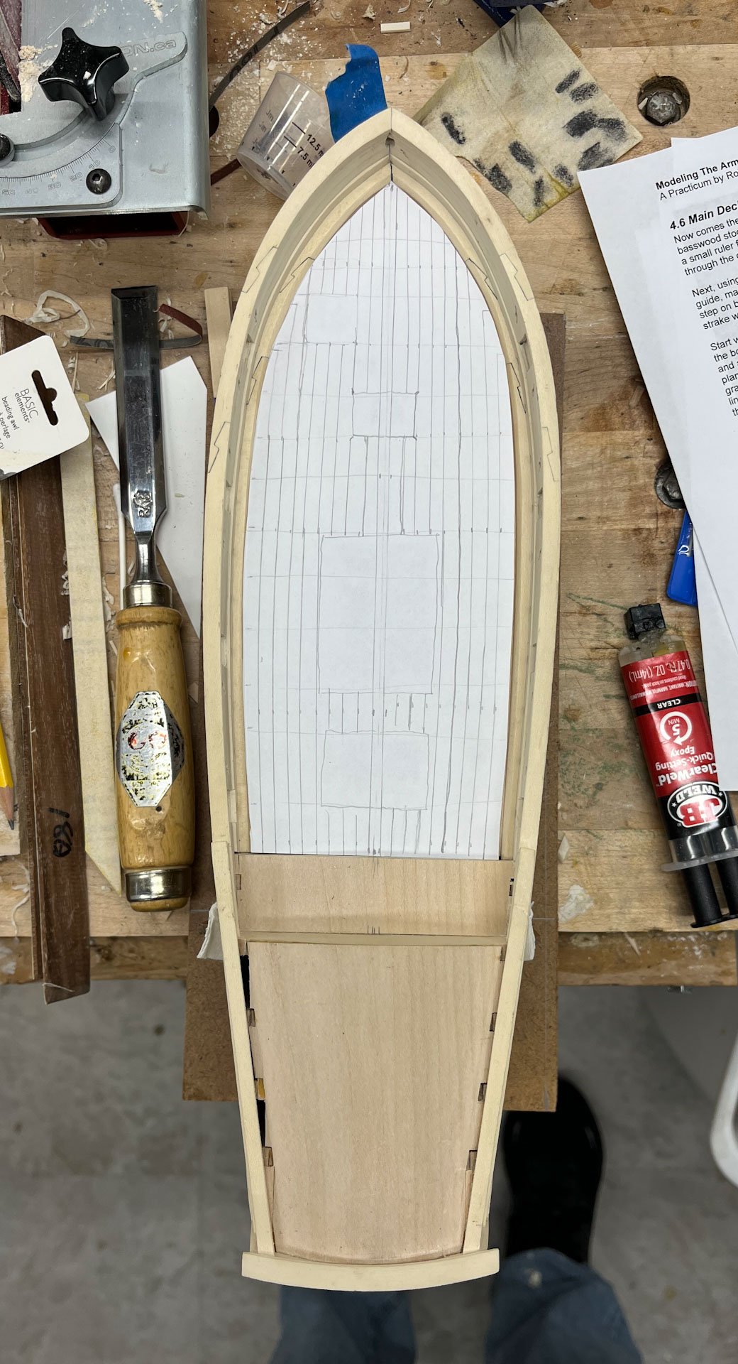
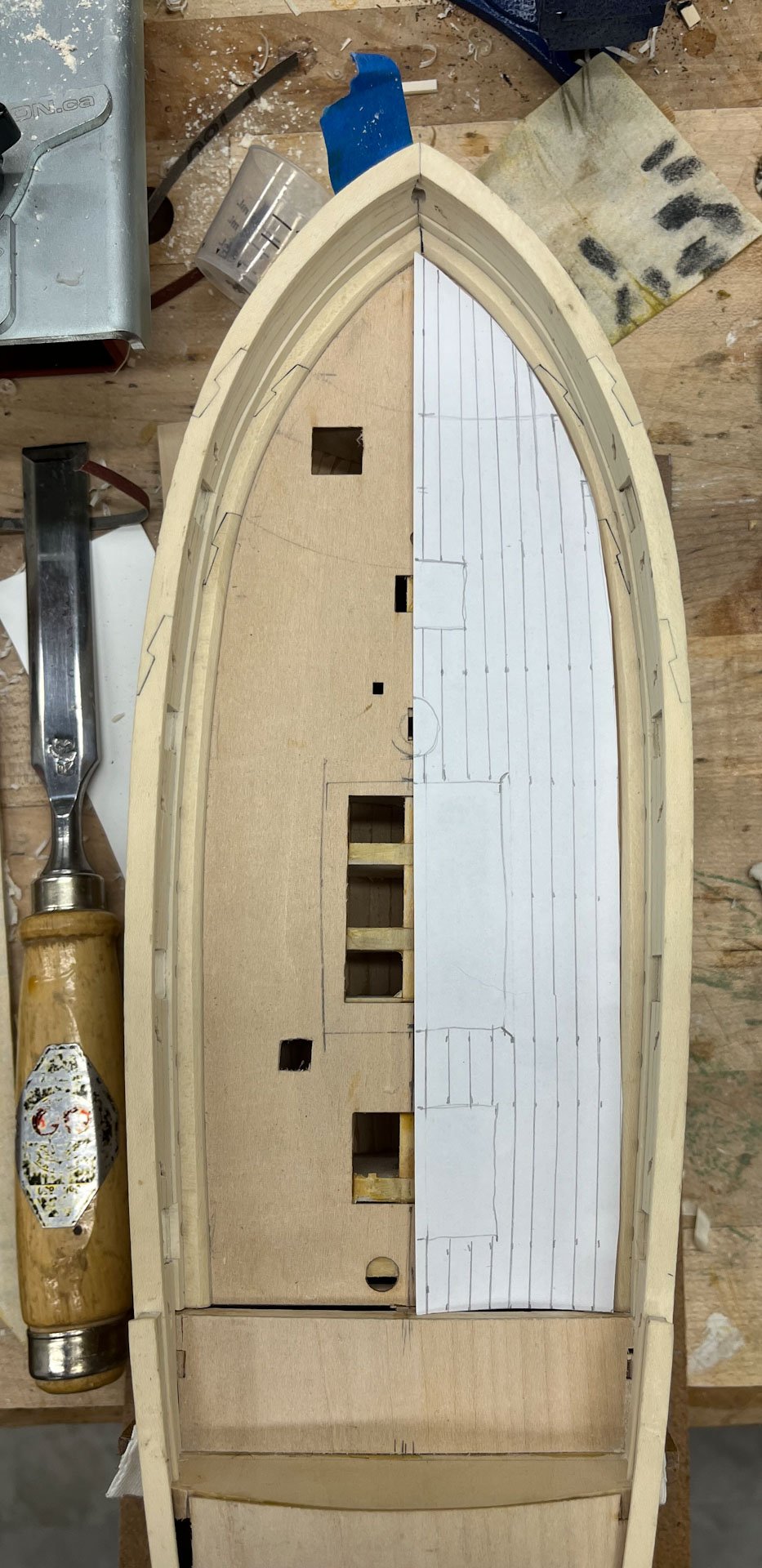
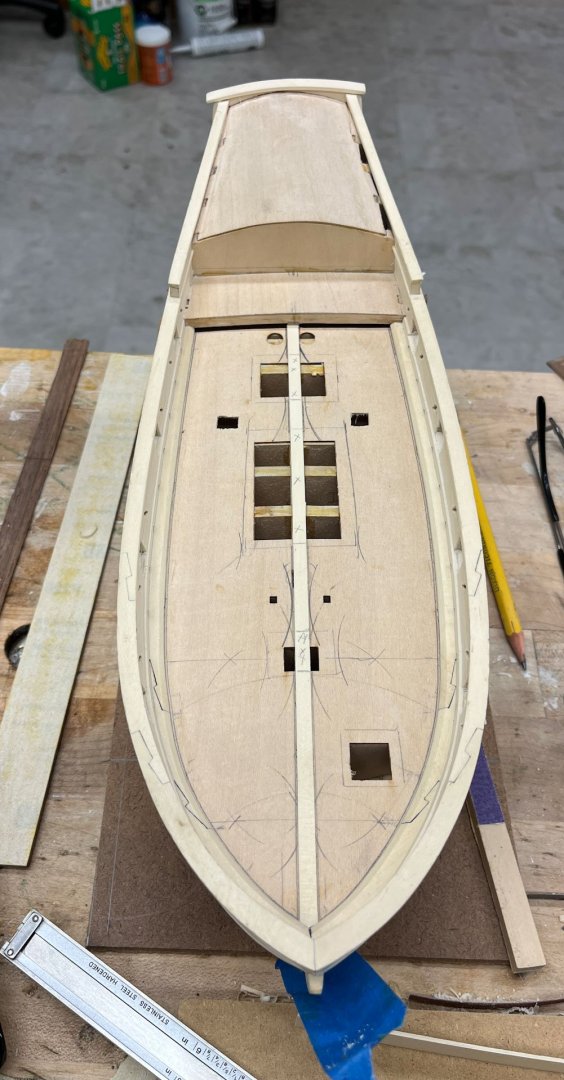
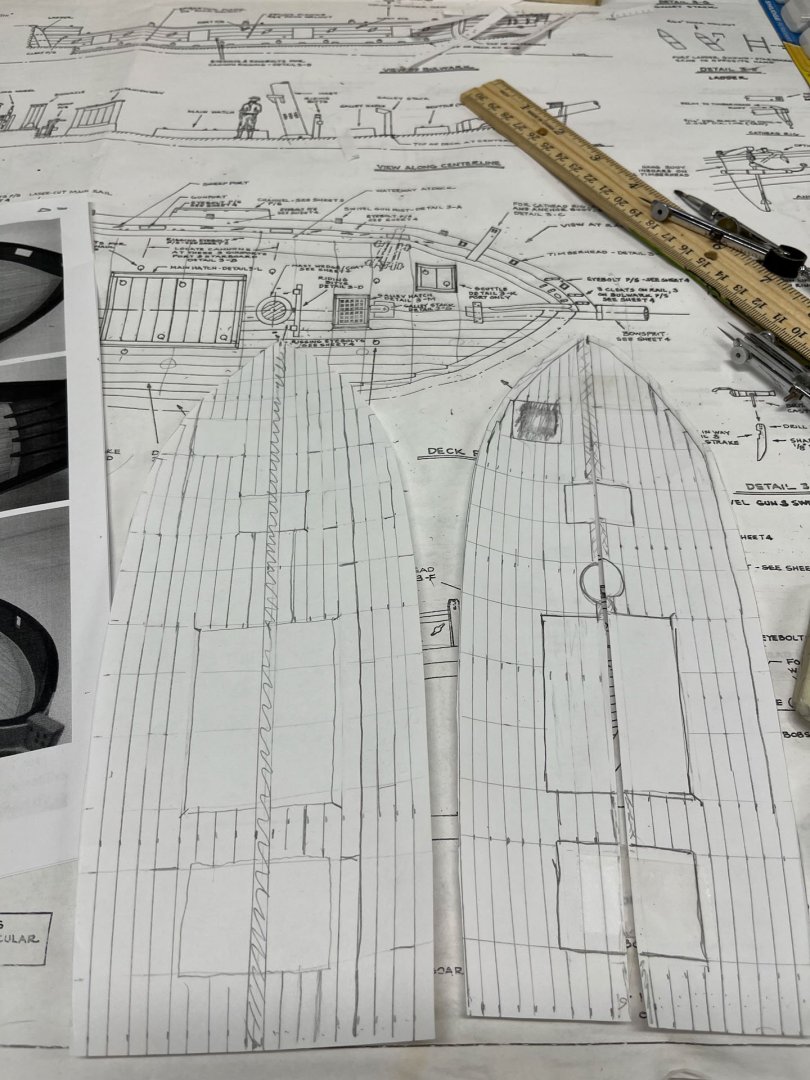
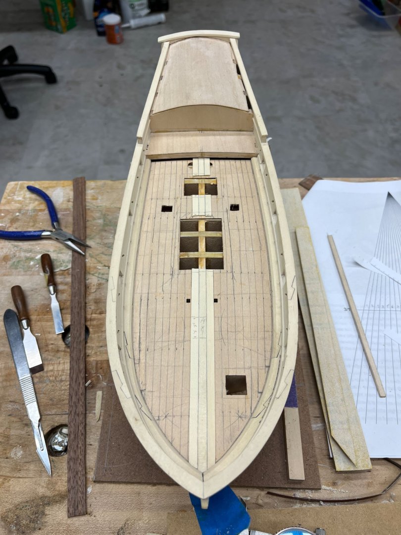
Planking the deck! A mid-flight update. After my last post I spent some time struggling with my planking plan. I liked the hooked scarfs and curved decking but worried I was making it too busy. The AVS also has that small extra grating, off center on the fore left side, that made life difficult. Version 2 of hooked scarfs is below on the Left. On the right I tried remaking the decking with nibbing and a margin plank (but still curved). It got uncertain on the port side where that extra grating is, which is placed to exactly interrupt the flow. Eventually I settled on the Version 2 curved hooked scarfs and by shifting the small grating a little I got it to line up with the planking better. I was worried I'd end up with some bizarre wedged hooked plank cut in half. I had drawn in the deck beams and traced the outline of each hatch and grate. But these were not perfectly accurate as all were wider by the thickness of a pencil tip. And they needed to be closely centered in a hull that (it turns out) is not completely symmetric. After some agonizing over my planking scheme (I want a 3 plank shift) and realizing that a mm or 2 either direction changed a lot of variables, I put having the plank shift finalized on hold until I was further along. Below I used my drafting compass, which is quickly becoming my most important tool, to find the center on the deck. It wasn't an exact straight line. Then i glued down the center plank. And now that I had a definitive centerplank to mark from I penciled the plan onto the deck. As I said before the sides are not perfectly symmetric so there will some fudging. Next up is adding consecutive strakes to either side and navigating the forward central grate. At present it looks to fit perfectly even with the next planks but we'll see. at least its not another darn window. Thanks for reading Cisco

-
HMS Surprise by Vincwat - scale 1/69 - Lego
CiscoH replied to Vincwat's topic in - Build logs for subjects built 1751 - 1800
complete with stunsl booms and hammocks in the hammock netting. very impressive effort by someone who clearly knew ships -
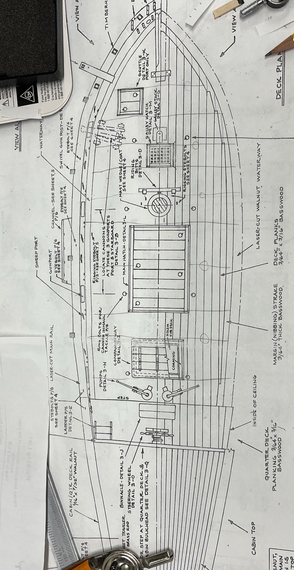
Well on to planking the main deck. The kit comes with a detailed picture and the LaukStreet practicum follows this scheme closely. Basically all straight planks except the outside one which is curved to match the sheer. The fore ends of the outside planks are nibbed into a secondary plank called the Margin, or Nibbing, plank which parallels the waterway. I think this was done because its easier (all the planks are straight and the same width, again except the outside one), the Margin Plank nibbing looks cool, and maybe also because its how Dr Feldman did the original model. (Although when I looked at the pictures in his book he has 4 nibbing planks per side while the AVS directions show 3. Again, maybe to make it easier). I have always liked the look of curved deck planking and I never liked doing things the easy way so off I went looking to make it harder on myself. I have used Cheerful as a source of inspiration for this build and I really like the decking Chuck did which was curved and scarfed. After a lot of thinking and the appropriate "mmmm hmmm" noises I came up with the following: I changed from equal numbers of planks on each side to a center plank, shown in the drawing above as a 1/2 plank in the middle, and 9 roughly 3/16" wide planks each side. I was having a lot of trouble getting the hook scarfs to cooperate especially the aft one which was weird and too long. Then I realized the hook scarfs are only used at the bendiest parts of the hull. In the Cheerful there is no quarterdeck or cabin so the deck planking runs all the way to the stern. In the AVS the main deck is only 2/3 of the ship's length and the aft main deck section doesn't curve much atall so it probably doesn't need any fancy joinery. So I did another template: I like this one better. From above its not as obvious but when you sight down the length of the ship the planking clearly curves. I need the currently uneven hook scarfs to be the same length so a small adjustment pending there. I got rid of the aft hook and now the planks flow much better. And if I want it curvier I can make the central planks a little fatter amidships. Throughout all this I found both Chuck's Cheerful instructions (Chapter 8 ) and Eric W's super clean (and well documented) Cheerful builds very helpful. Next up is cutting the planking from my holly billets and not second guessing myself. thanks all Cisco

-
Get used to edge bending. Most of the remaining planking will need to be bent or it will gap upwards, as youve found. youre re-do looks perfect. I found Chuck’s planking videos very helpful, along with reading his Cheerful planking directions. He covers dividing the remaining space into Belts of planking that taper typically at the stem. I think most people also recommend putting in the garboard strake early. your planking is spotless, keep it up
-
it does look like a bit of a peak in your pictures. i think it will cause headaches planking the stern if it stays so pointy, so yes i would consider sanding it down like you said
-
Hey now! thats a work of art
-
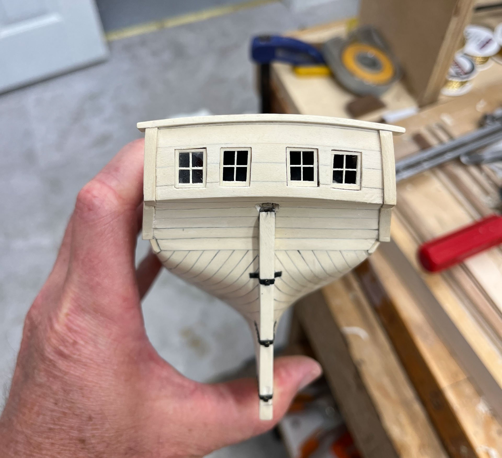
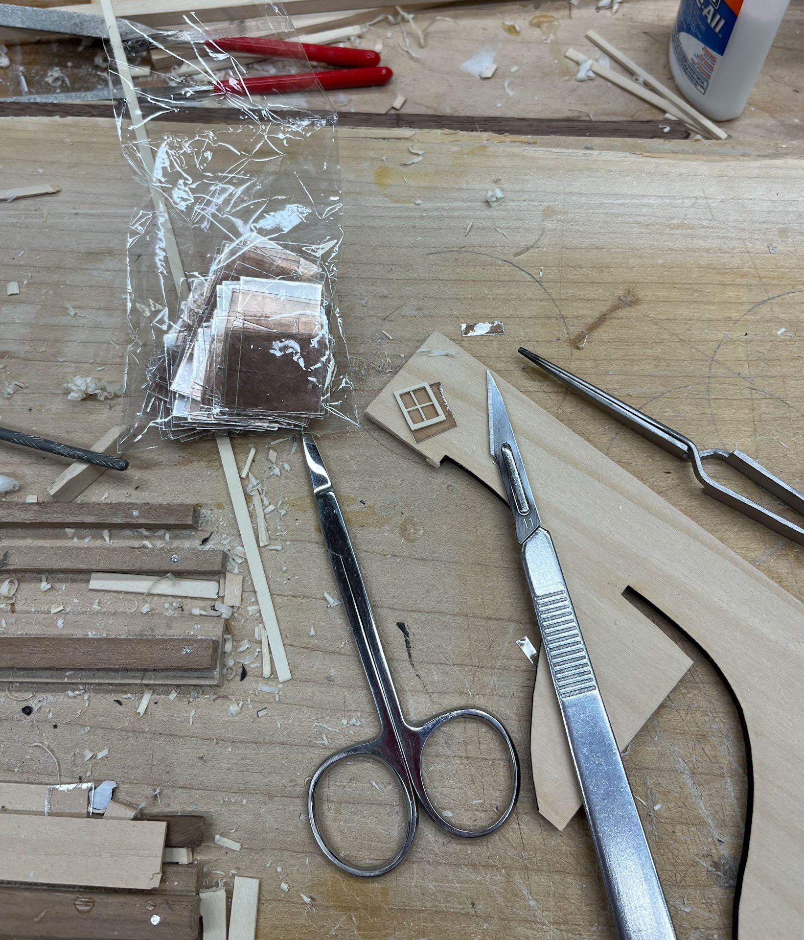
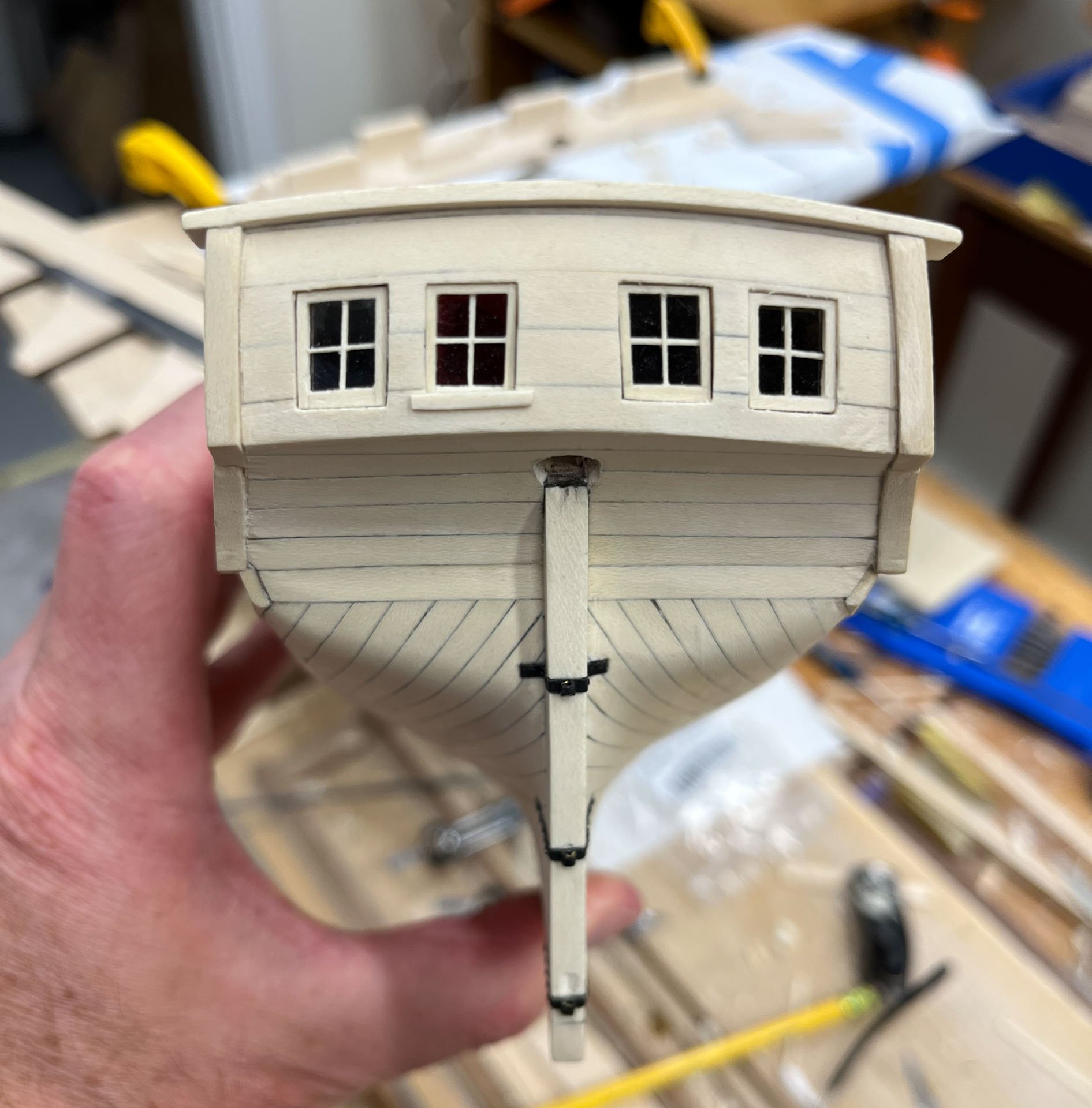
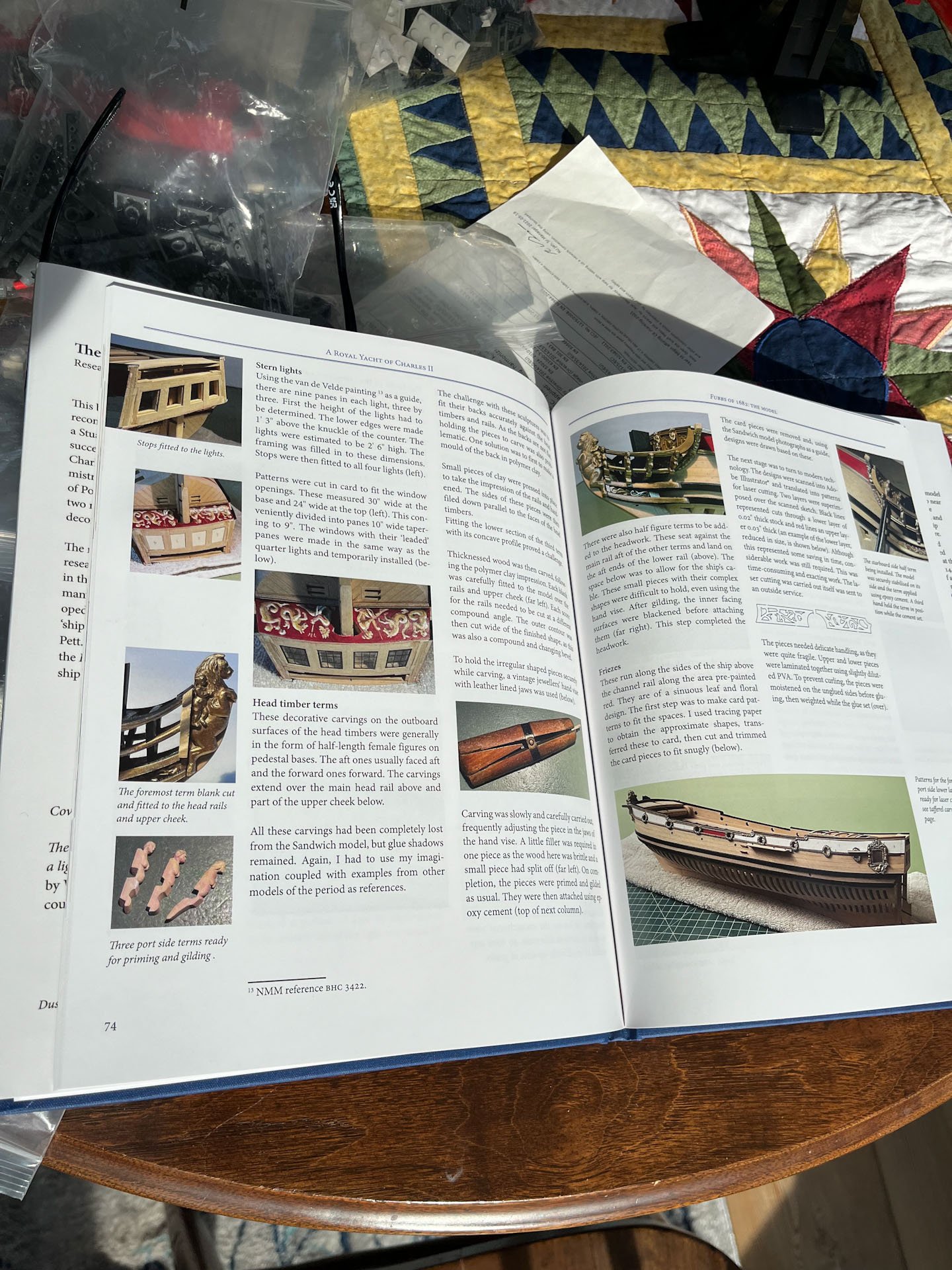
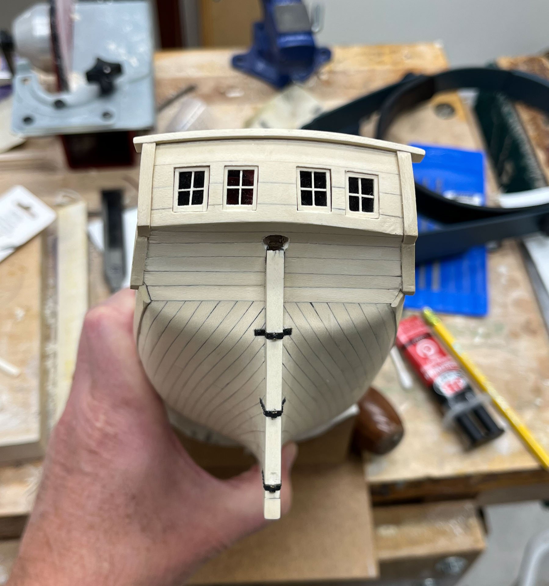
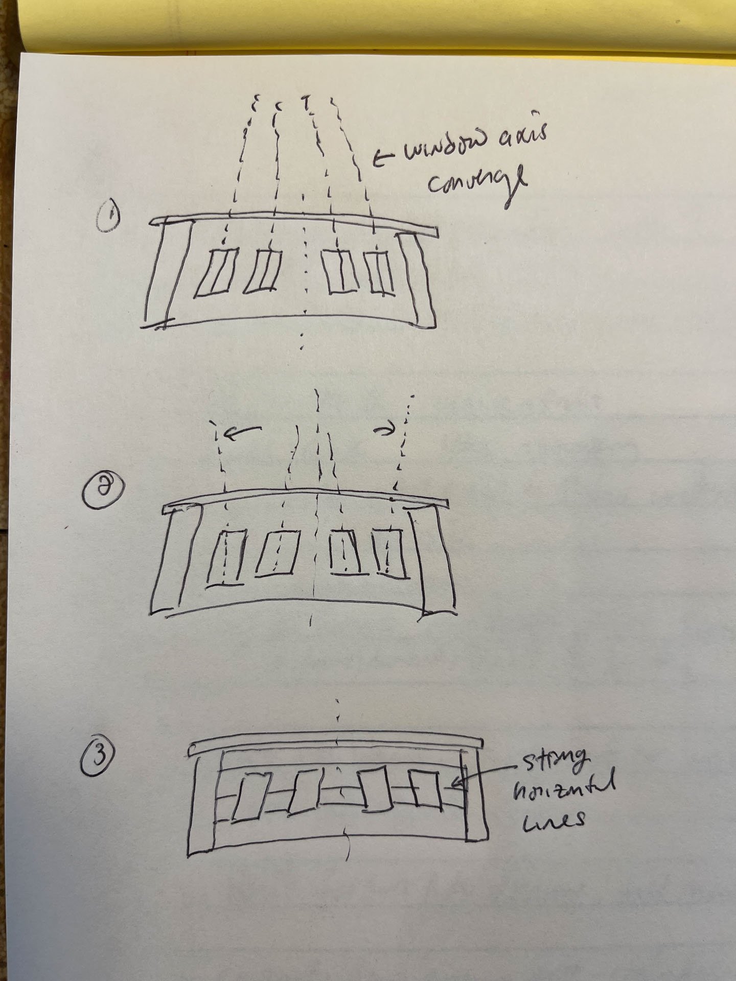
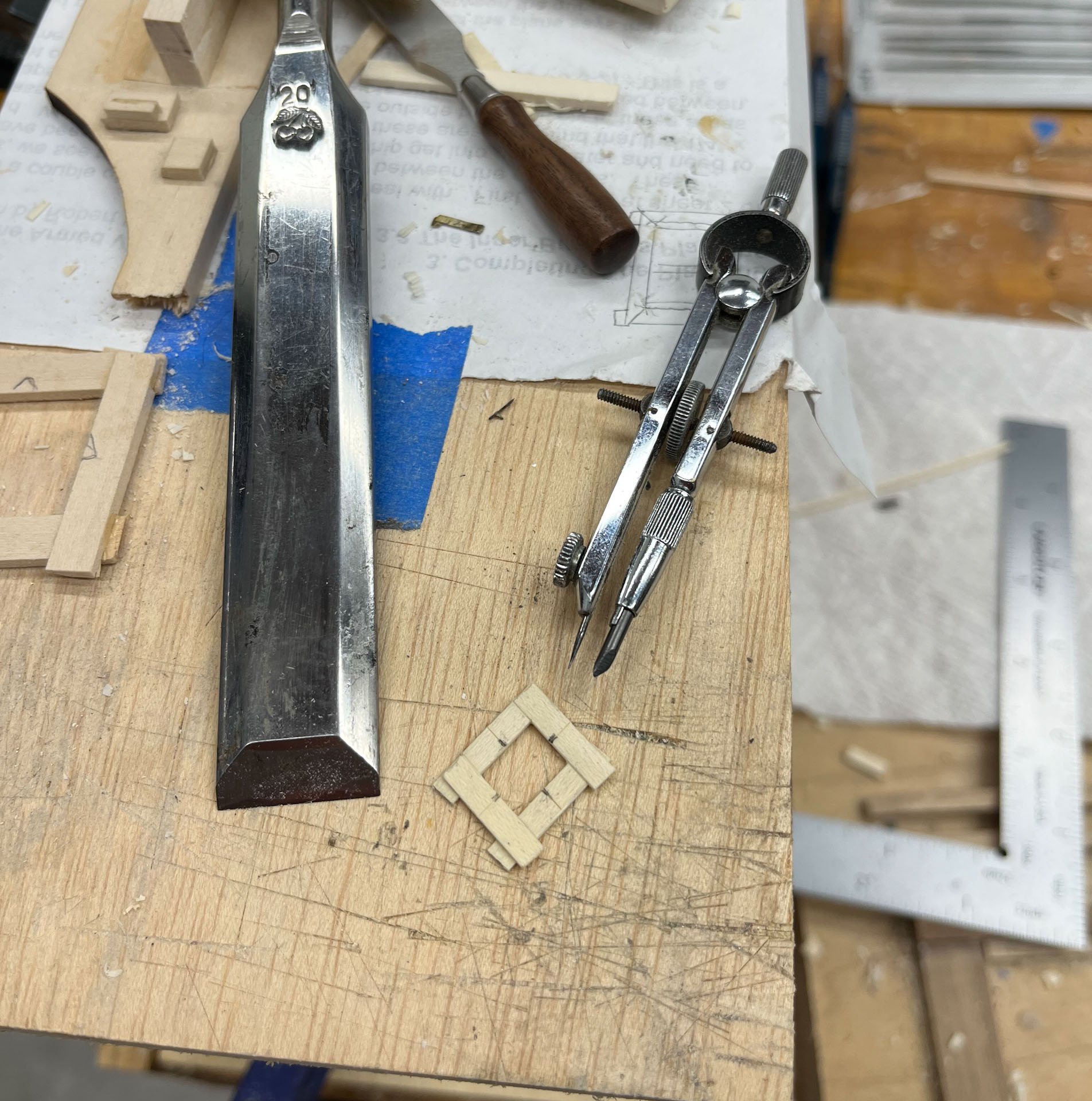
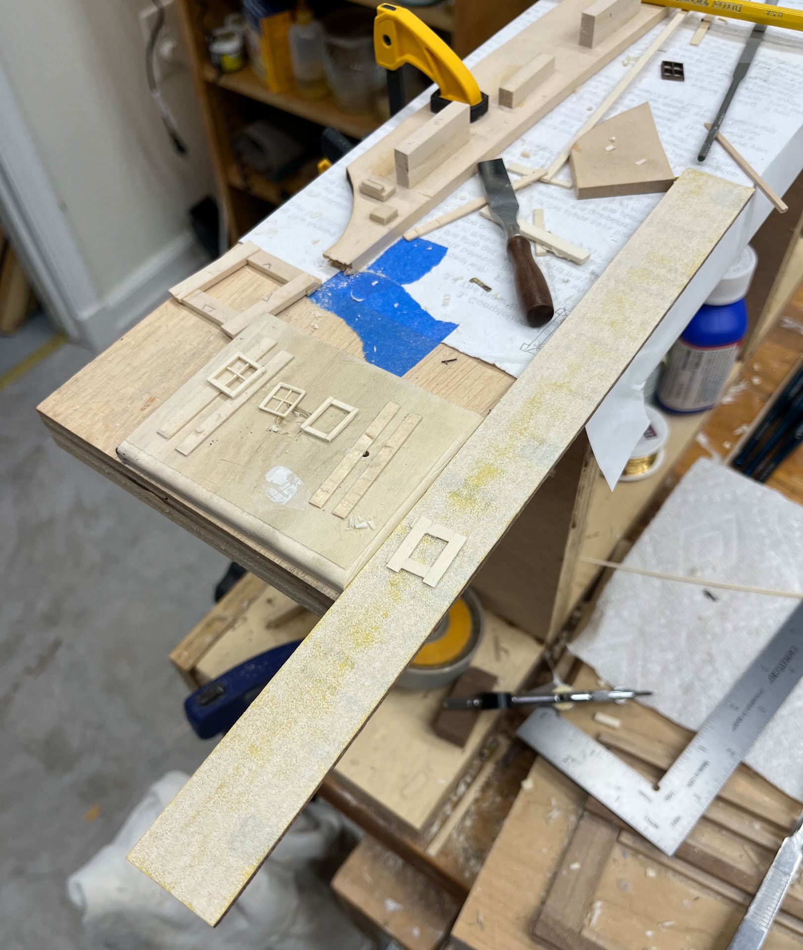
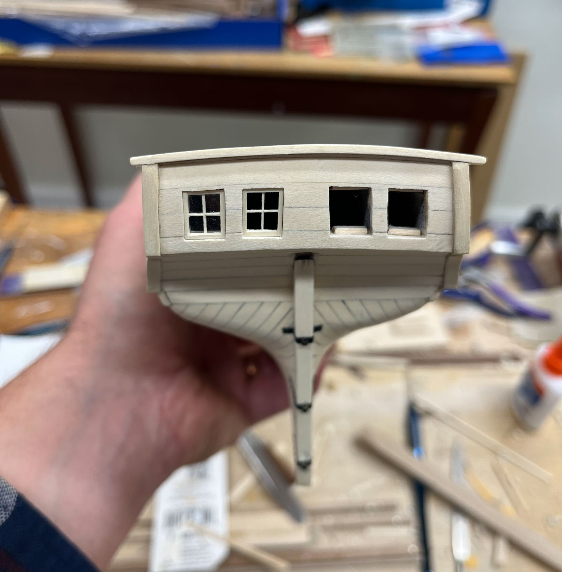
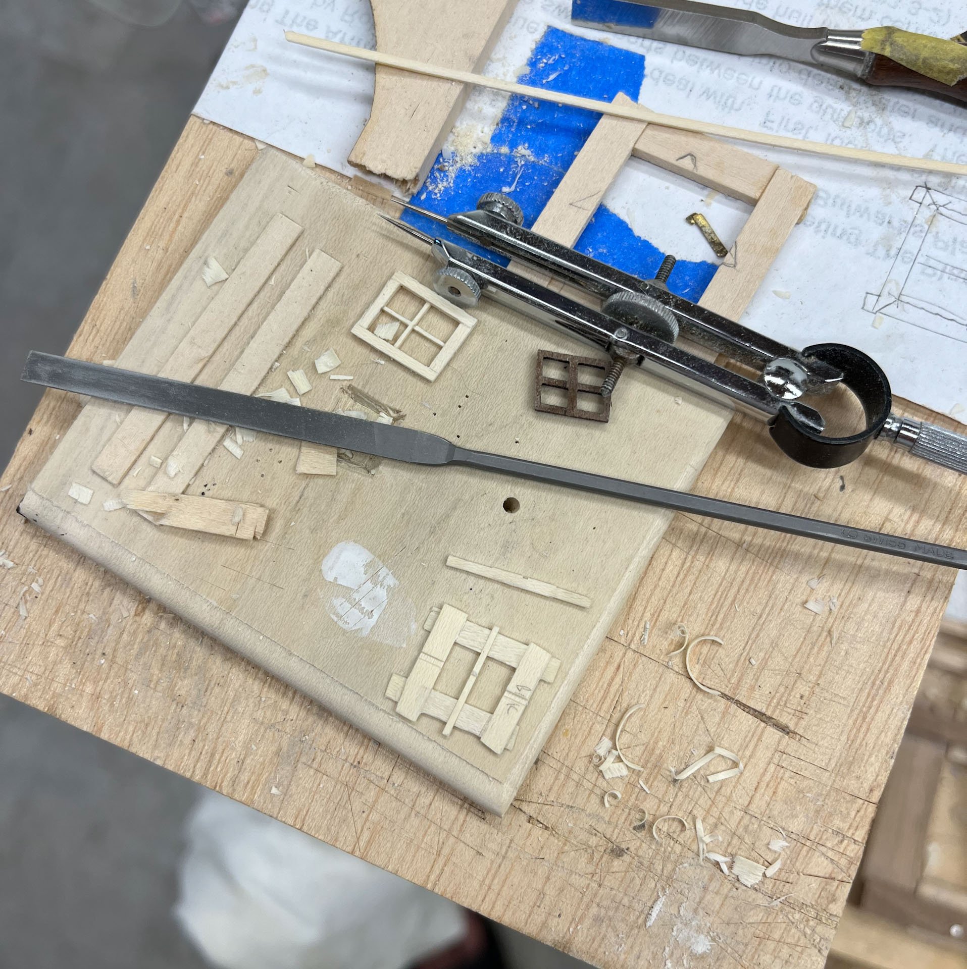
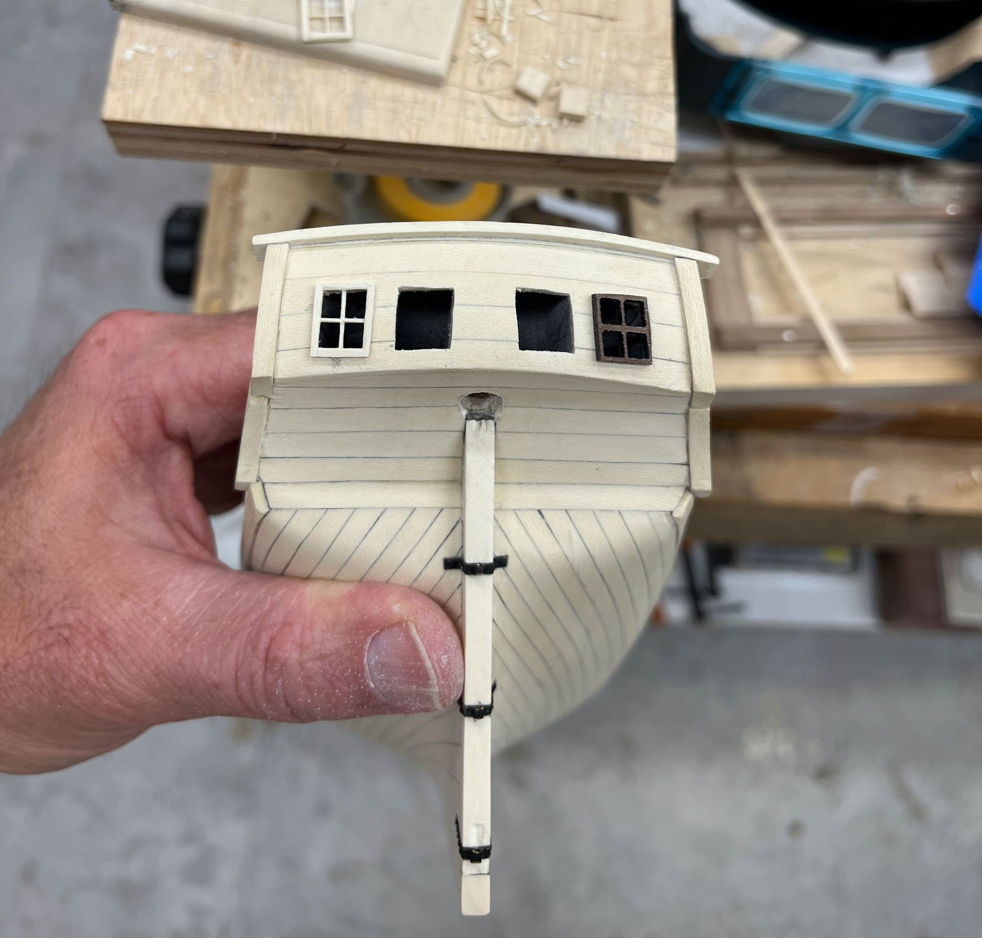
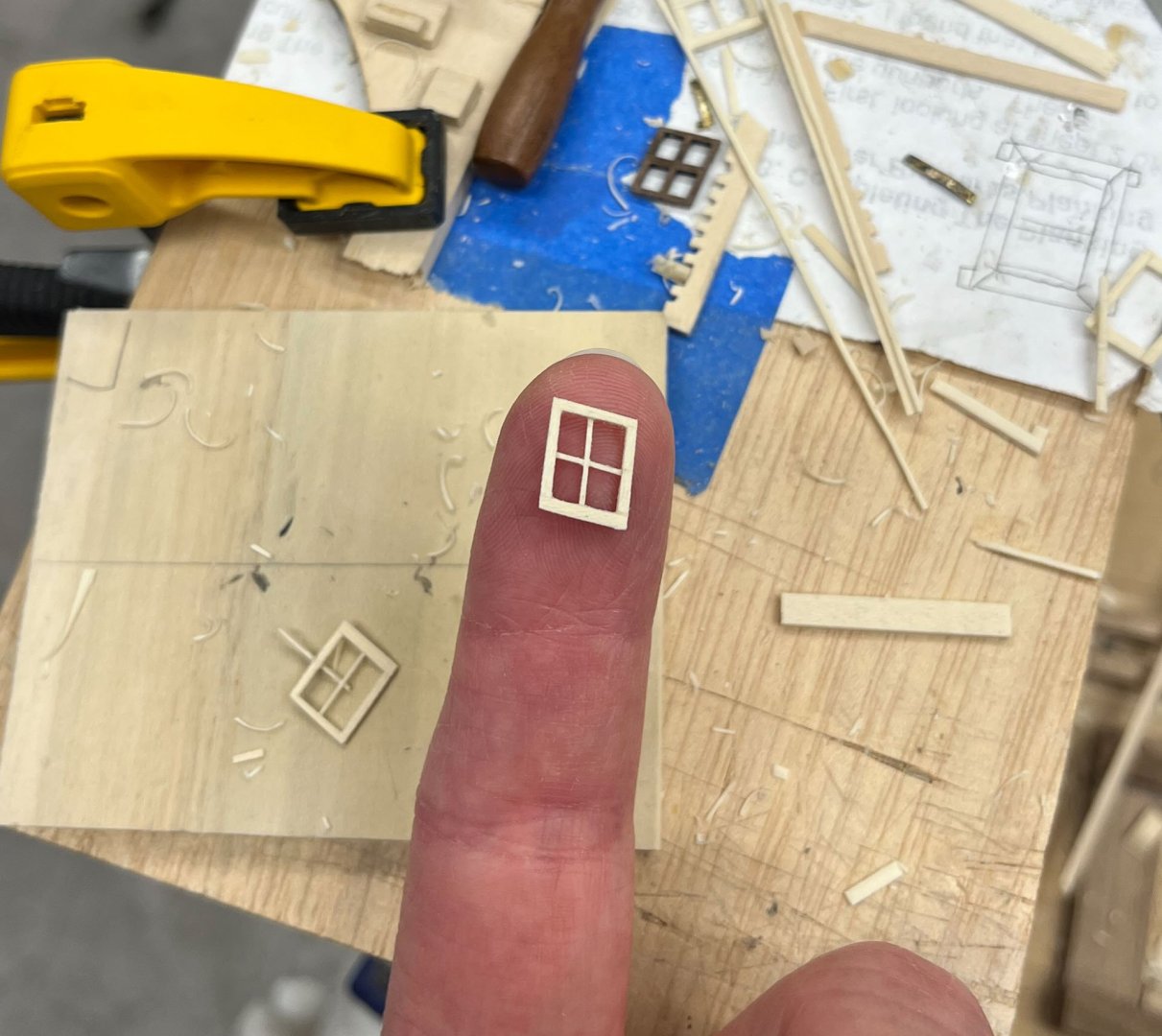
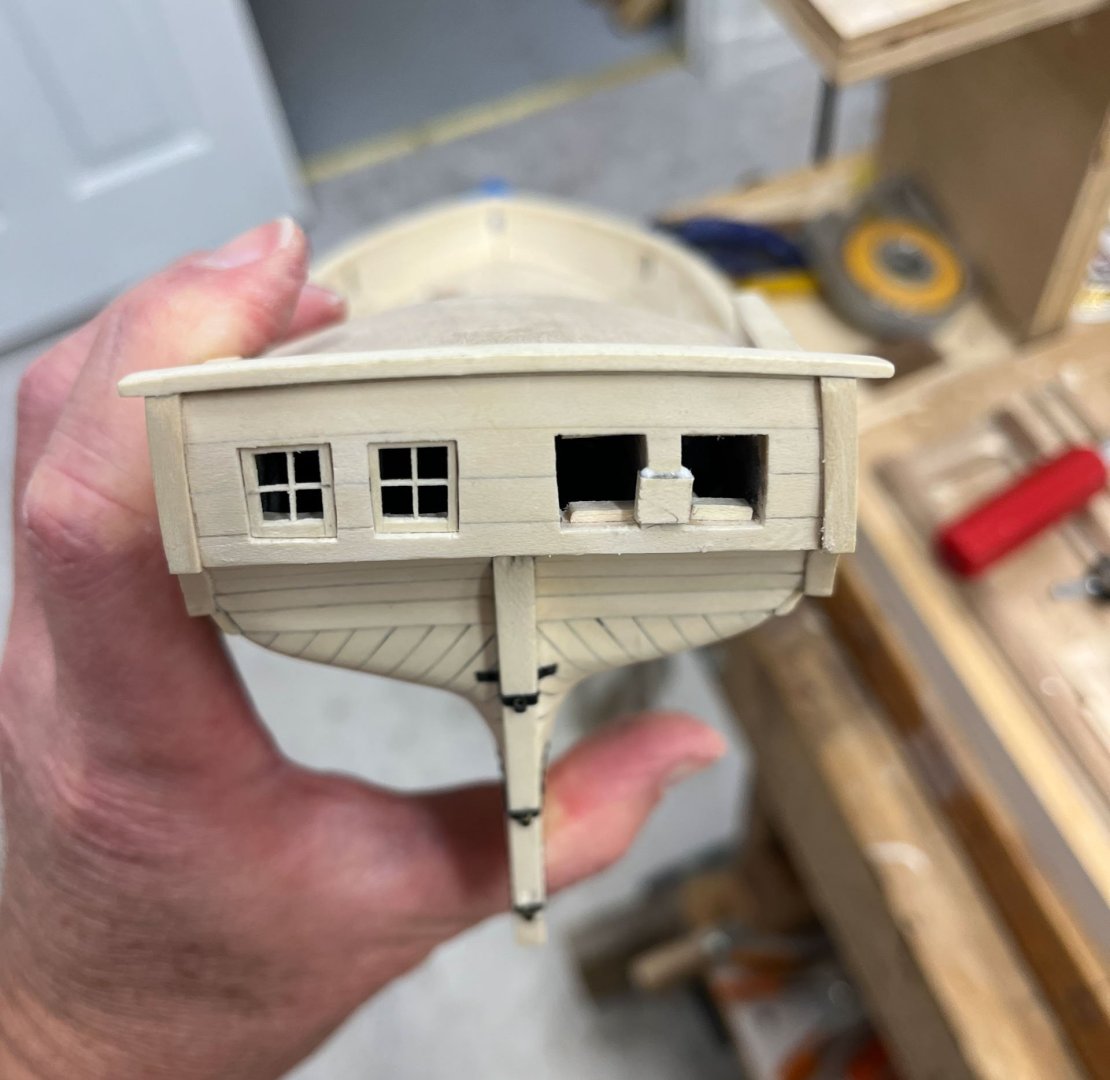
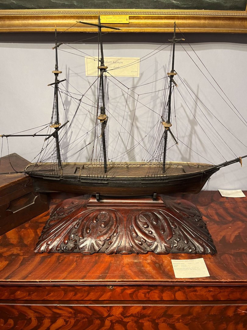
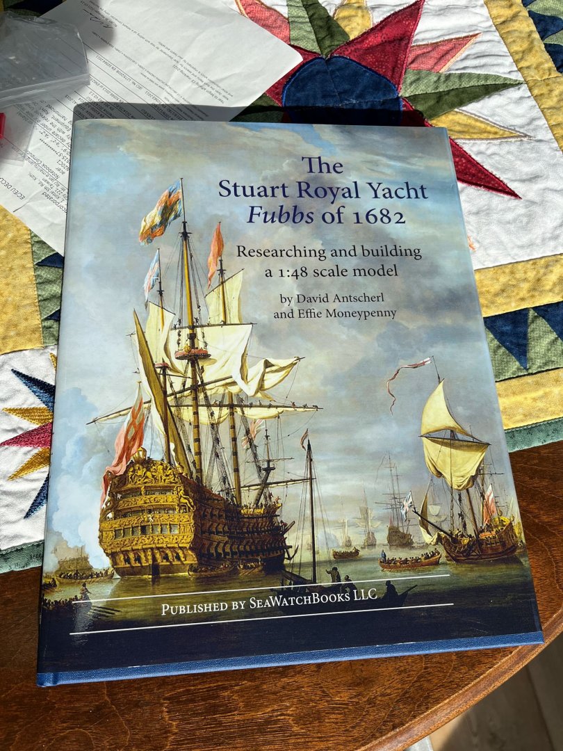
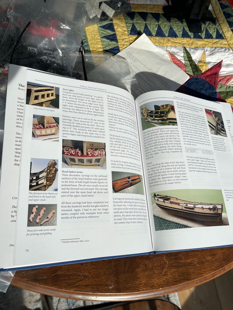
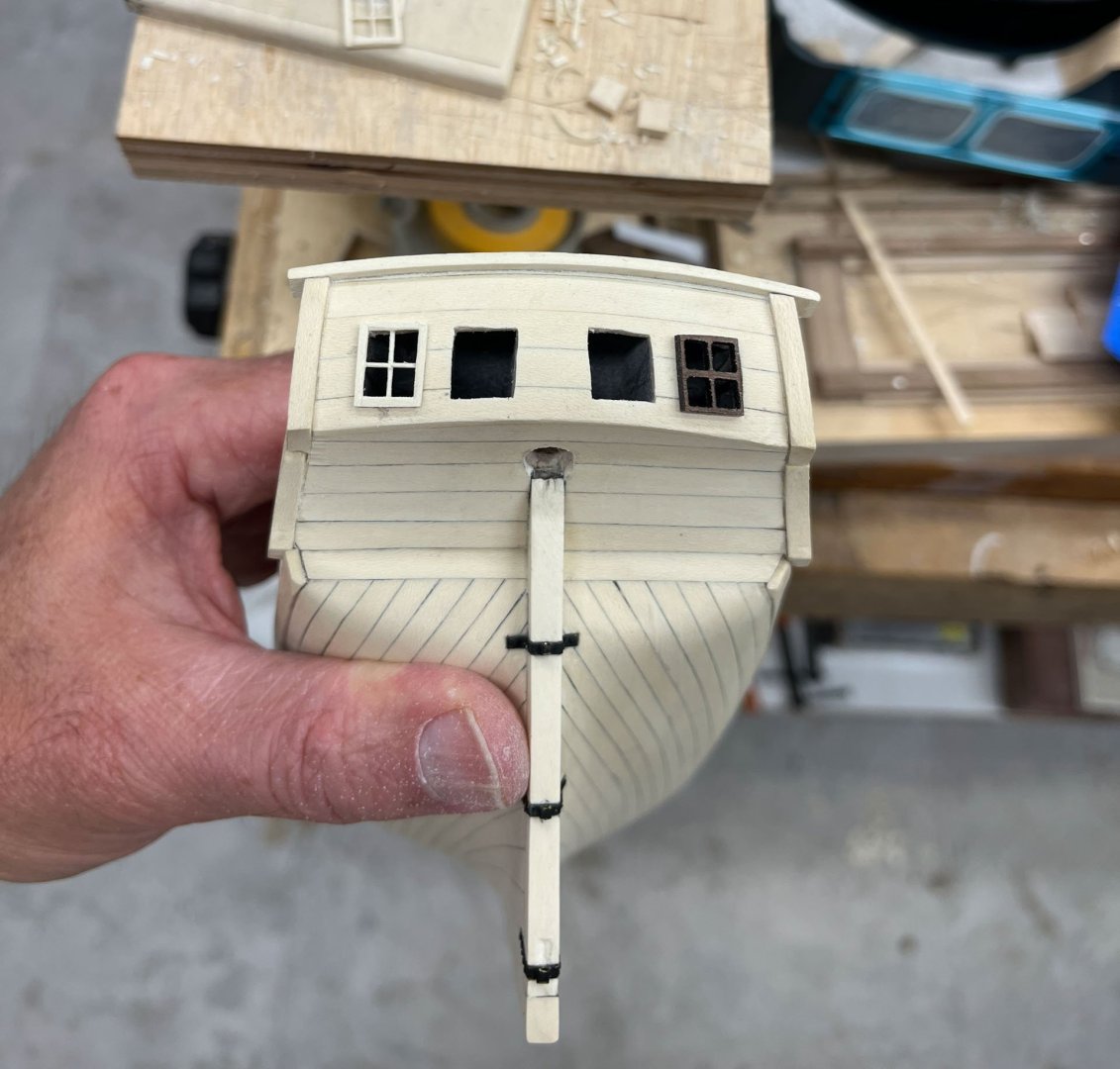
More Windows Well I'm back. Windows have been driving me crazy and I'm happy to say this update will finish them for better or worse. Here's an example to remind us of how small the darn things are. I have had good luck getting the muntins to 1/64" reliably so thats a plus. I made all 4 windows and filed them to fit. It was a great day! And they looked acceptable to the naked eye, until I took a picture. To my eye the furthest starboard and port windows looked off kilter. Their vertical muntins seemed to be angled outwards. And the inner and outer horizontal muntins were not lining up. I think its more noticeable due to all the strong horizontal and vertical lines around the windows. See my cartoon below - in a row of stern lights the line of the vertical elements should converge somewhere far above the stern, as in picture 1. There is also the tapering edges of the stern, what the instructions call the fashion pieces but I think are called something else, that further emphasize this convergence. My window axis are more like picture 2. There is also the added lines of the stern planking which normally would be painted and less visible. When the horizontal muntins don't follow the horizontal line of planking its glaring. You can also see a small gap at the base of the the inner starboard window where I overthinned the wood between the windows. Nothing for it but some planking re-do and window deconstruction. In the new windows I exaggerated the angle of the outer vertical muntins and shifted the horizontal muntins in 3 of the windows so they followed the line of the horizontal stern planking better. This made the muntins often not centered in each window frame. Being a traditional-minded builder I wanted mica for my windows and found a cheap (10$ ish on Amazon) bag of precut pieces; they are the size and thickness of microscope cover slips. I found tracing with a scalpel blade, then bending or cutting with scissors the easiest way to shape them. Sanding or filing made the edges fray too much so i tried to slightly undercut the panes. They are hard to see once in place in these pics. And then how to make the window frames stay in place? I tried making a sill but I don't think it looked appropriate in such a small vessel, see below, so no go. All the other genius ideas I had for fitting a secondary frame were not working so I decided KISS and why note glue them directly in place? First I tried putting glue in the window holes and then setting the window frame on top but it always smooshed the glue out onto the mica. Eventually I found it easiest to put a very little line of white glue on the top and bottom of each window frame with a toothpick. Using a tweezers I then set them bottom-first, then swung the top in. They were already a snug fit and the glue filled the gap fine. A veritas minichisel worked perfect to scrape any squeezeout, which if you use very little glue was mostly none. Here's my finished product. I am now tired of windows and this is whats going to stay. I had to make some compromises to follow the line of the planking; none of the window openings are exactly symmetric to the other side and the windows are also each a little different. I suppose it it ends up really bothering me I could hang a jollyboat over the stern to hide my sins. Ok done with windows. few other pics- I was at the Delaware Antique Show last weekend and saw this. The base is amazing and way out of proportion to the fairly drab model ship and I thought it was pretty funny. And yesterday I got my copy of Fubbs which I have been anticipating for the last year. If you like David Antscherl's other books you will like this one too. Here's the page on windows; too late for me on this model. His muntins are perfectly aligned, of course. ok that it. Thanks for reading all. Have a happy Thanksgiving, those of you who celebrate it. Cisco


-
Recommend Model Shipways kit to buy (with my new credit)
CiscoH replied to palmerit's topic in Wood ship model kits
my first ship model was the 18th century longboat. it was challenging but rewarding (i really like the finished product) and it got me hooked on this hobby. presently i’m building the armed virginia sloop and its a good step up in complexity yet small and simple enough that i have a chance of finishing it. i personally dont like prefab parts like etched sheets, printed single piece decks, and resin carvings; i would rather make all this from scratch which is what you can expect from these kits. i have an active build log for the AVS that i update every few weeks here on MSW. you can also get clayton feldman’s book, there is a practicum by Laukstreetshipyard which i found helpful, and Chuck’s Cheerful directions are also often pertinent. so lots of extra help out there should you want it for the AVS. -
amazing!
-
what Aliluke said. i broke a bunch of the tabs off too
-
super clean planking Jeff. Looks excellent!
-
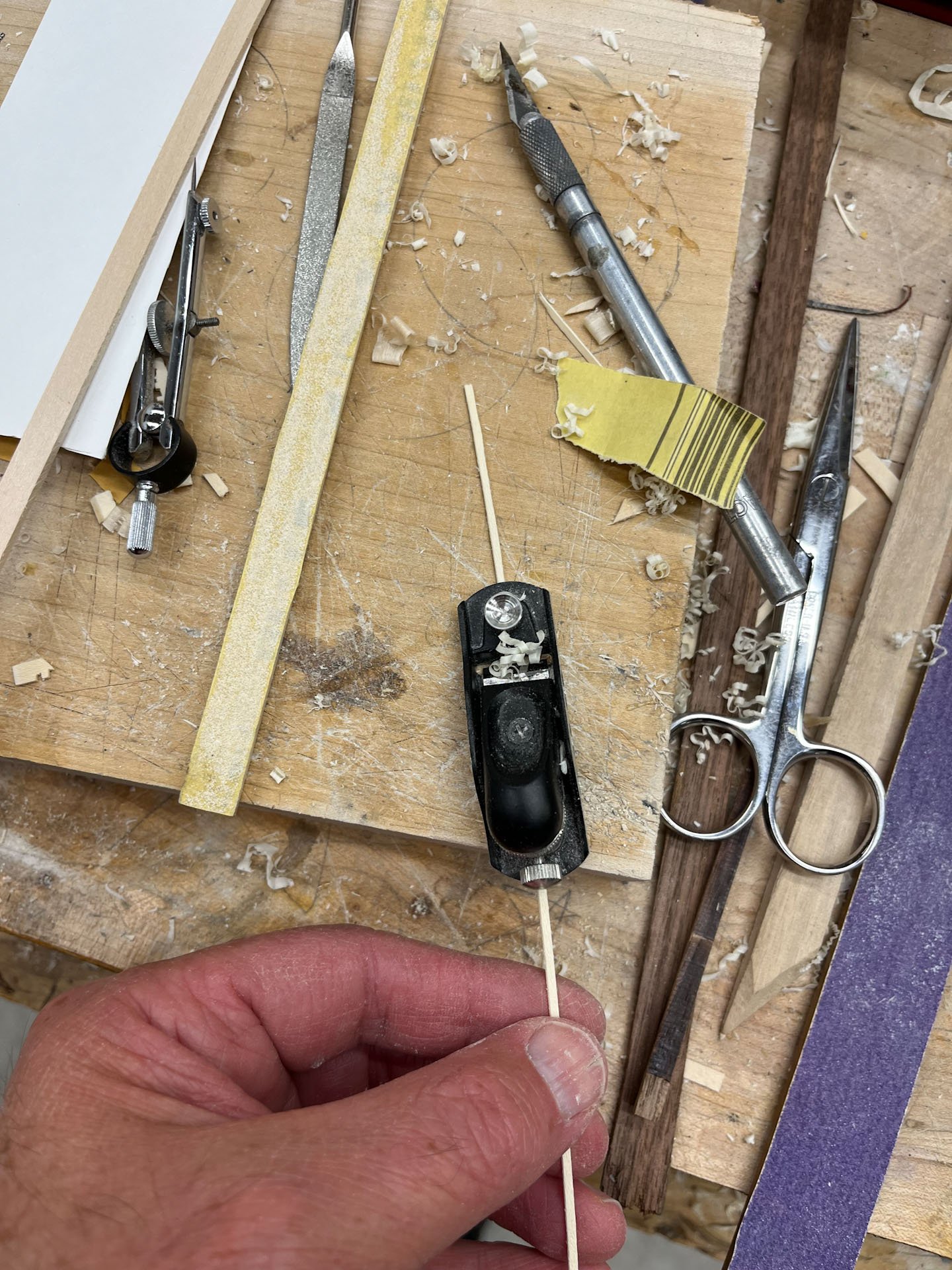
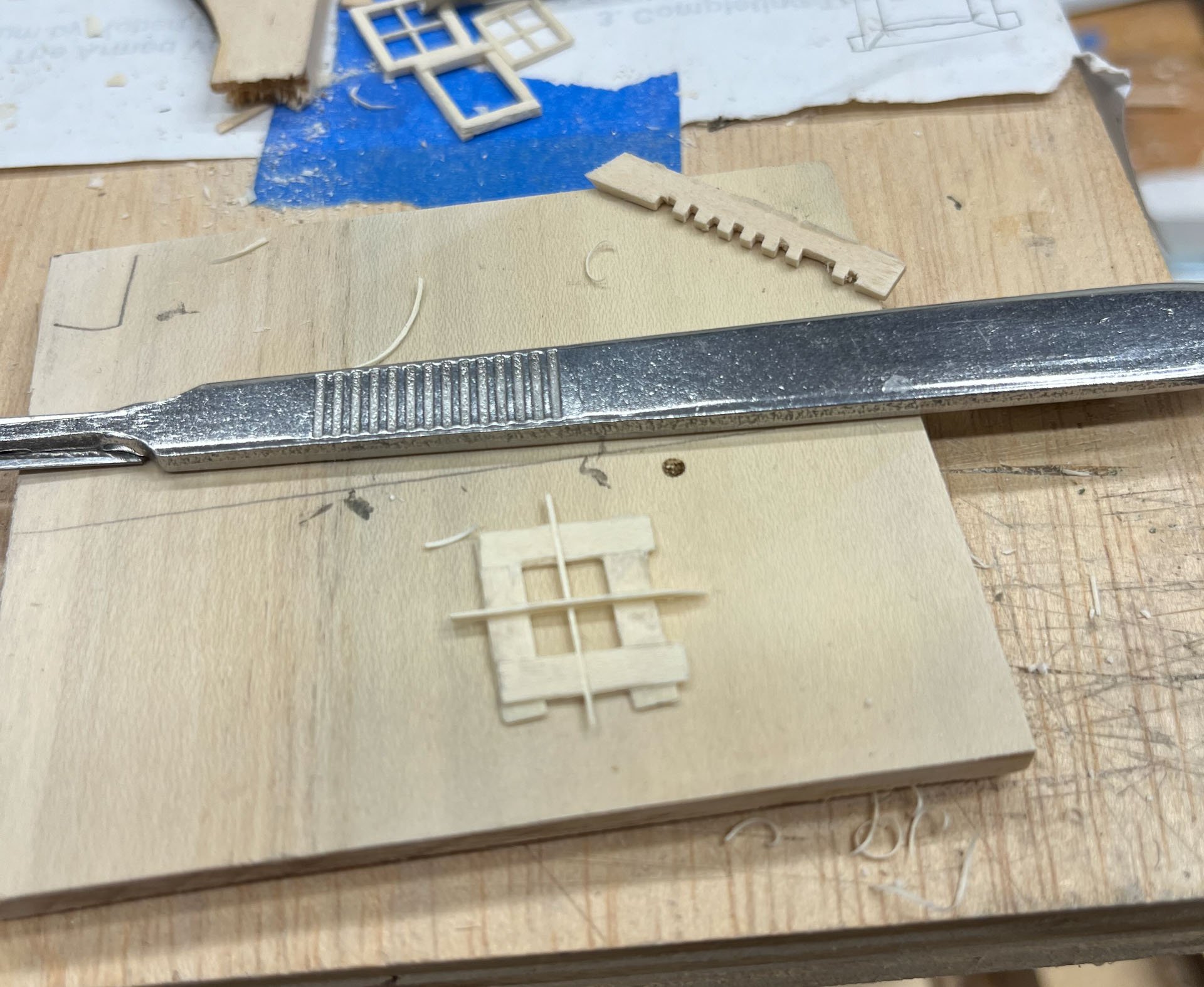
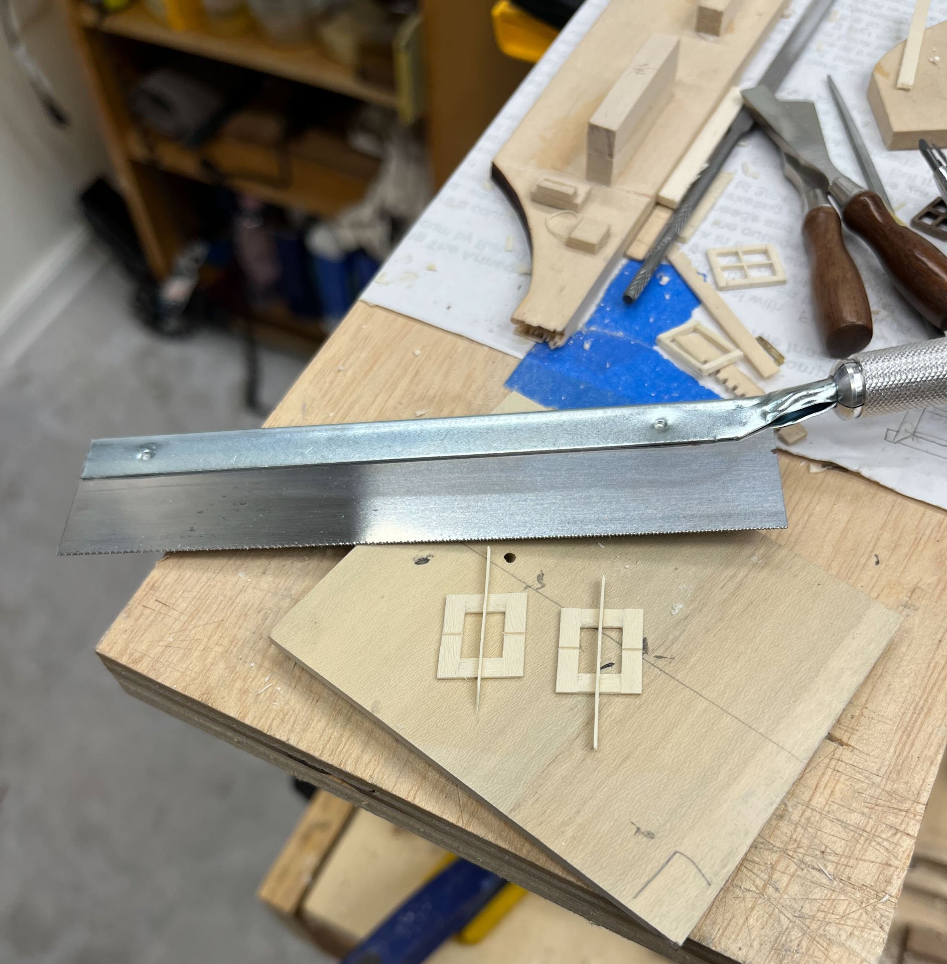
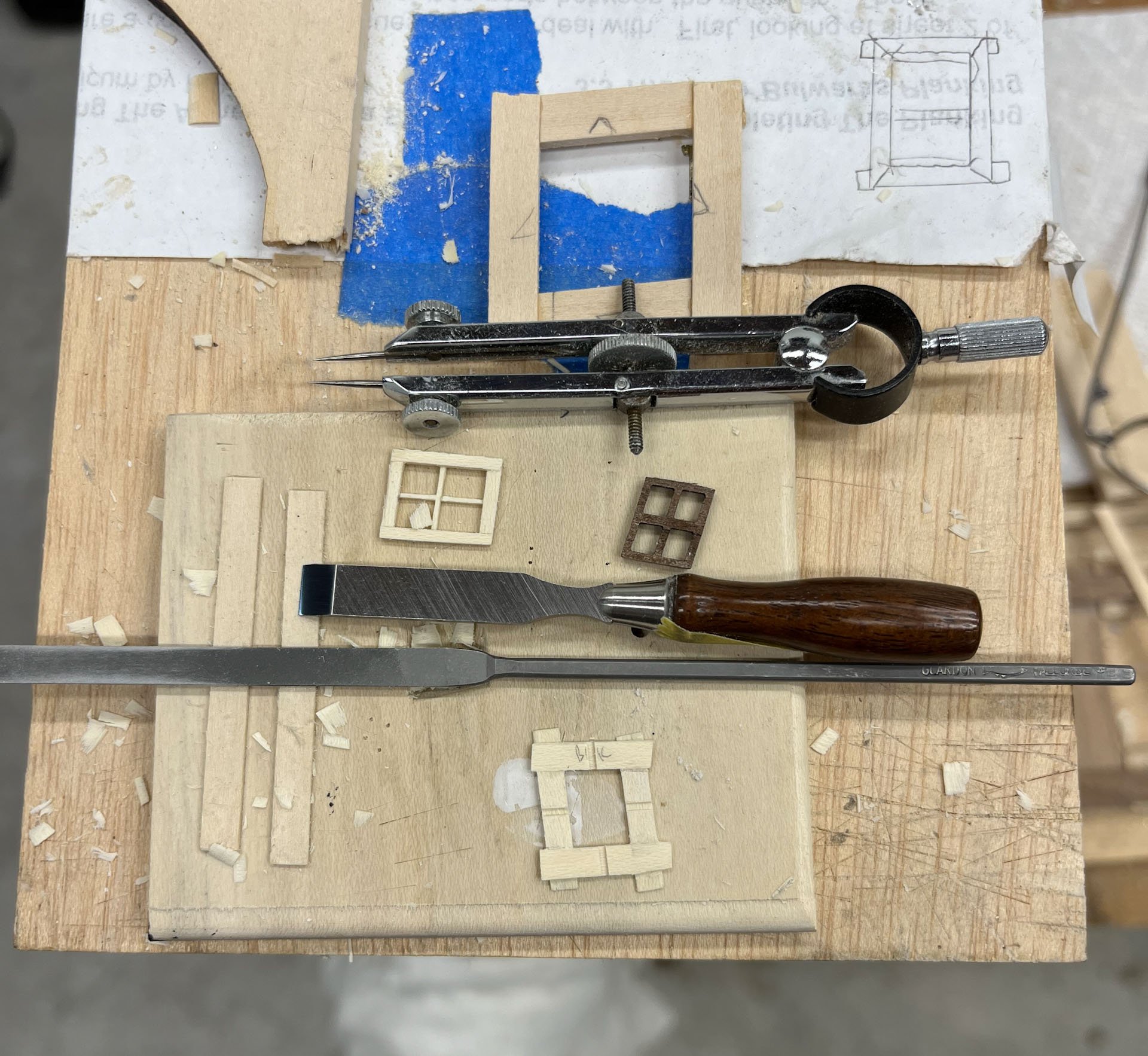
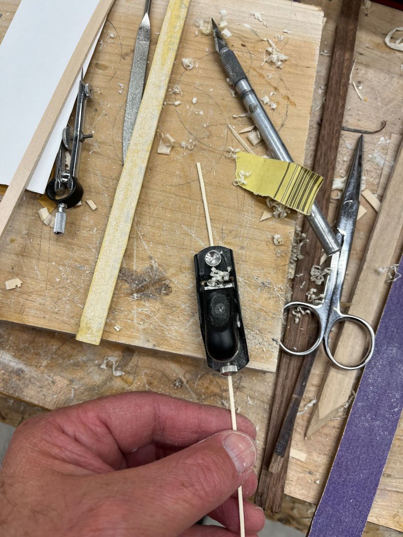
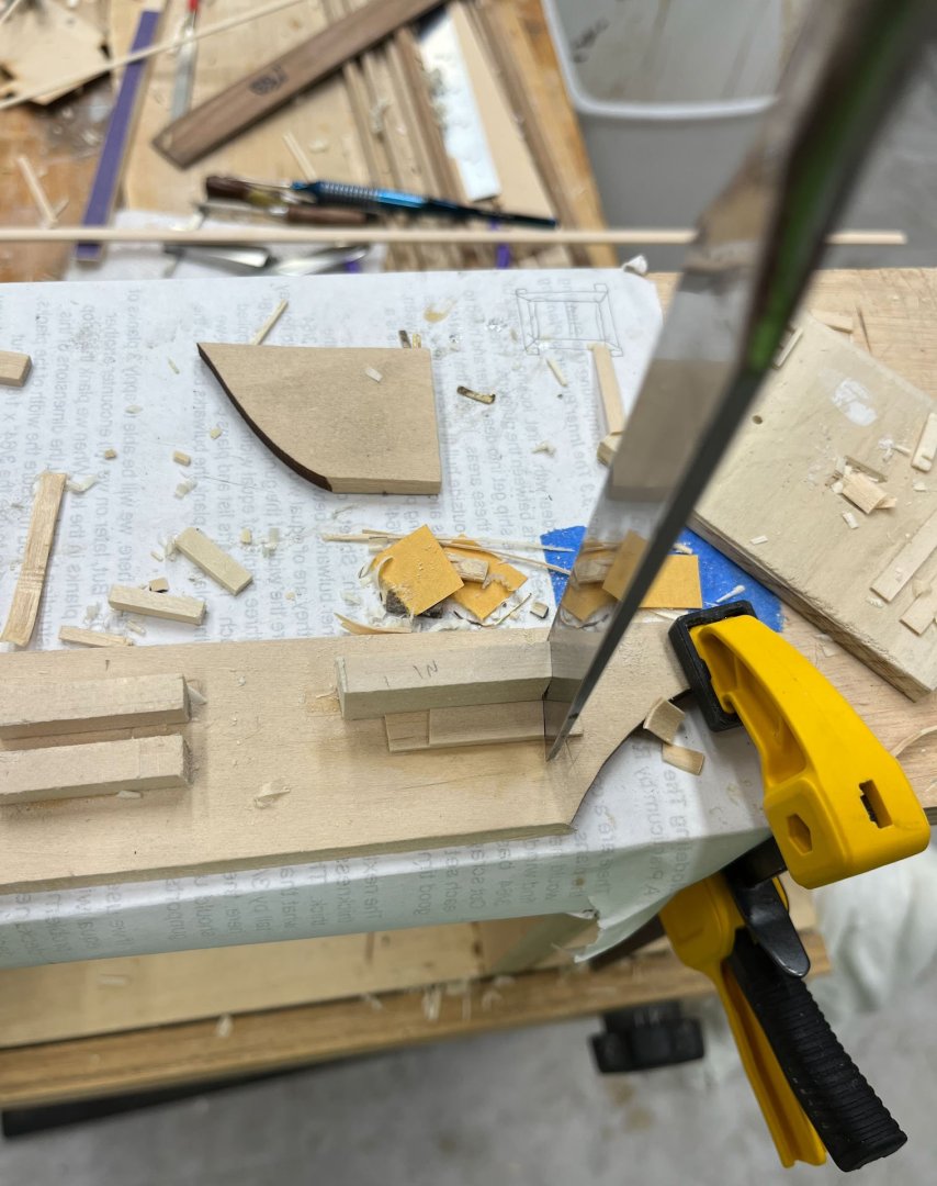
Good Sunday evening MSW. Here in Delaware Daylight Savings has struck so its dark at 5:30pm. The drama those with kids call "Halloween" has receded, time for an update. Today is Windows Part II and I am afraid there will be at least one or two more to come. Like everything in this hobby they are a lot more complicated than I expected. My big difficulty, besides simply the challenge of working with such small parts, was making the same size windows. Its easy to make several Almost the Same Size frames but with all 4 of them side by side tiny differences are glaring. So I tried to think up a way to make my parts identical. I also wanted skinnier muntins; my previous beefy 2/64" ones weren't going to cut it. My first solution is pretty practical and thankfully simple - a pair of stop blocks. First I glued one on the closer side of my angled jig. I pushed each frame part snug against the stop block and cut the angle with a Veritas mini-chisel as before. Then I glued another stop block on the other side of my jig to push against so my second cut was at the correct interior frame dimension. Repeat with another piece and now I had the 2 side pieces of the frame, both exactly the same. I made another jig that cut the exact same angle but with closer stop blocks to make the bottom and top pieces of the frame (the window frame is slightly taller than it is wide). Once I had my 4 frame pieces I formed the half laps same as before. Once glued up with clear-drying white elmers glue I sanded both sides of the window flat with 220 grit. The window frame is skittery and likes to escape fingertips but I finally got the frame to a consistent thickness. Then as before I marked the center of each frame with my drafting compass and gently pressed the larger chisel across the frame on the pencil marks. I used the veritas mini-chisels to cut a tiny wedge at each chisel incision. In my previous post I used a file to cut the muntin mortises but my smallest file is 2/64" wide. I couldn't find a thinner one so I went back to using my hobby saw (see the last pic in this post, its the red handled one everyone has) which is exactly 1/64" thick. If you go slow and gentle it will sit in the tiny wedges and cut a perfectly even 1/64" mortise. Then I used my veritas mini-plane (what would we do without Canadian ingenuity?) to sneak up on a 1/64" muntin. I would get it pretty close then use some 220 grit on a small stick to smooth the muntin to its final 1/64" dimension. I found it easier to work with if I left it big, as you can see below. Once it had dried I carefully trimmed the muntin down until it was even with the back of the frame (chisels must be sharp and mind the grain) and very very carefully cut a mortise in the muntin with first a chisel and then the hobby saw, supporting the fragile parts with my finger from underneath, and then shaped and glued the second muntin, oversize, in place. One it dried overnight I trimmed it up, a little more sanding to get it the correct shape, and inserted it into the stern. Here I have both port side windows installed. David Anstcherl talks about lining up the muntins so they make a perfect arc across the stern. I don't think I have that in me this go around. Below is my hobby saw and the 2 starboard windows with their vertical muntins drying in place. Next up, assuming the windows look good, is trimming down the interior stop blocks so they don't show through the windows, trimming my panes of "glass" (I'm using mica) and then making some exterior frames to hold the windows in place and smooth out the silhouette of the raggedly cut window holes in the stern planking. thats it, thanks for reading Cisco


-
Doug- that is exactly what i did on my last build. faired the bulkheads, added the first layer of planking, and realized this was an opportunity. i both practiced my plank layout, practiced bending and twisting the planks into place (with heat and a little water), and treated it as a chance to re-fair my hull. the second layer i made no attempt to overlap seams although it happened a lot by chance. having a solid wood base made the thinner second layer adhere so well i dont think staggering the seams would have made a significant structural difference
-
great post explaining your process!
-
Problems with blackening brass
CiscoH replied to Desertanimal's topic in Metal Work, Soldering and Metal Fittings
check Blackening Revisited by DVM27 about 3 pages in on this thread. my personal experience is blackening brass is very frustrating and there are a lot of Mystic Formulas out there. i sand the brass with 220, rinse in alcohol, and use the same blackener you do. i’ve had better luck distilling the black at least 10:1 with distilled water (10 parts water to 1 black). it takes 10-15 minutes to blacken and i turn the pieces over periodically. i still get small splotches where it doesnt cover, especially on soldered areas where i didnt get all the flux off, but the very dilute blackener seems to stick better than concentrated. then i use black paint on any areas that didnt cover. -
i had to add several strips and sand some bulkheads down to get them even. the false deck and sterncabin plywood panels will hide a lot on the topsides but you do want a somewhat level base. i did the same on the bulkheads lower portions to get a smooth run for hull planking. moving right along
-
I may be opening a can of worms here but how do you navigate copyright in this instance? Its a ship that isn't fictional, but the author's imagined ship kind of is. Replacing carronades with long guns isn't too controversial, but other details (like the enlarged mainmast which I know you are not including) theoretically could be. Also i am very interested in following along the kit development process. Its like magic how fast you develop your kits from scratch! I'm inching along on my 2nd kit build and after 2 years have almost made it to main deck furniture.
-
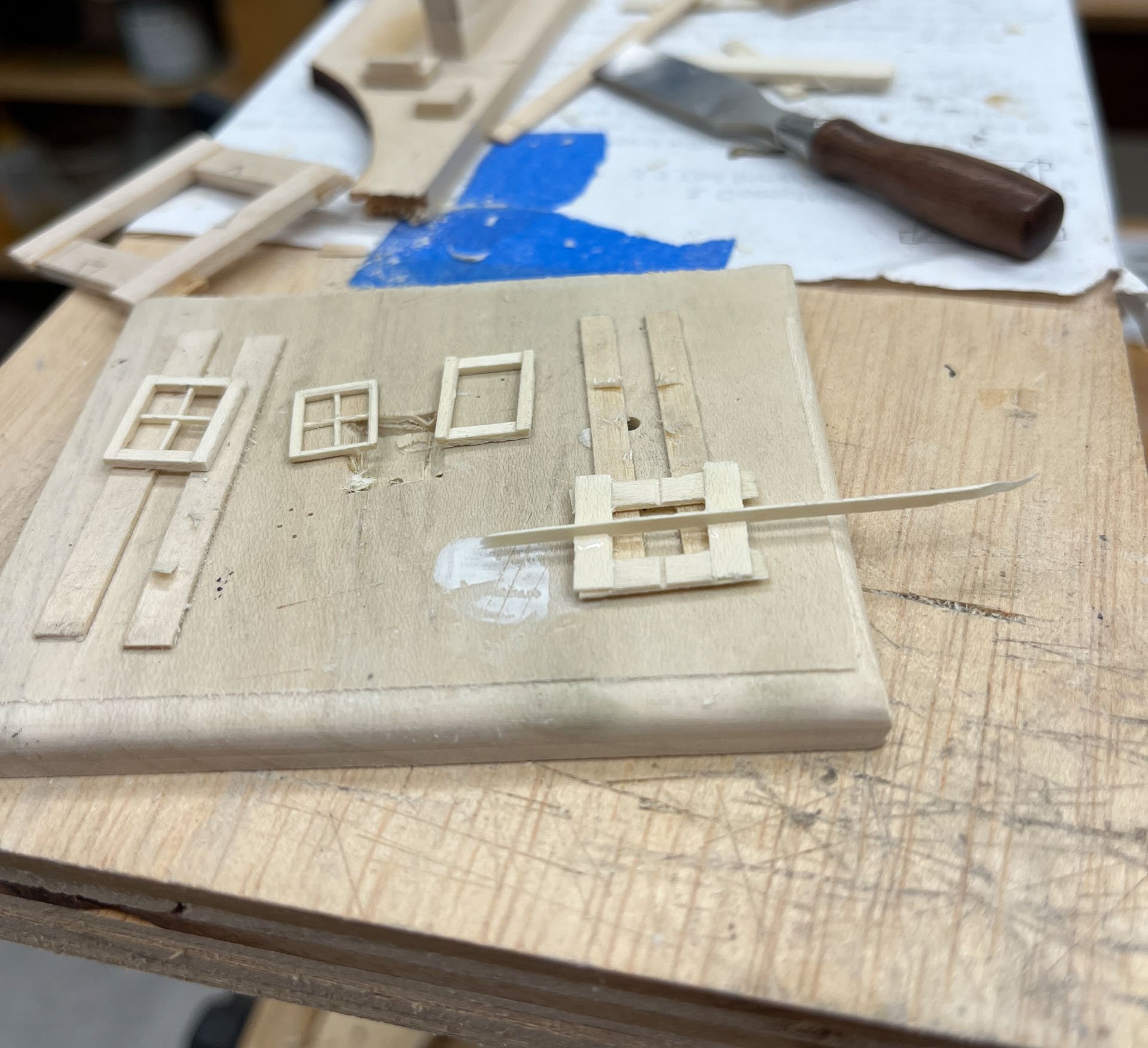
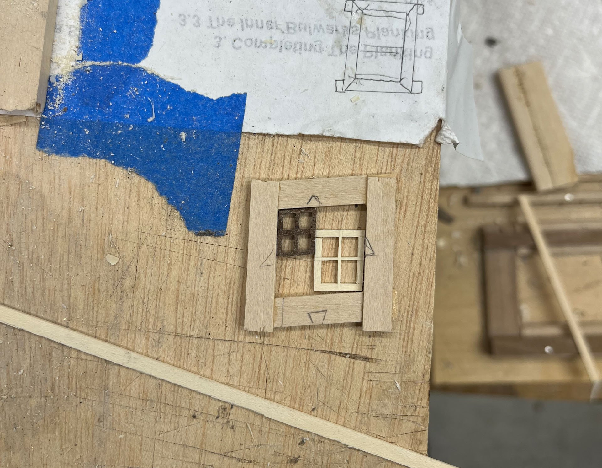
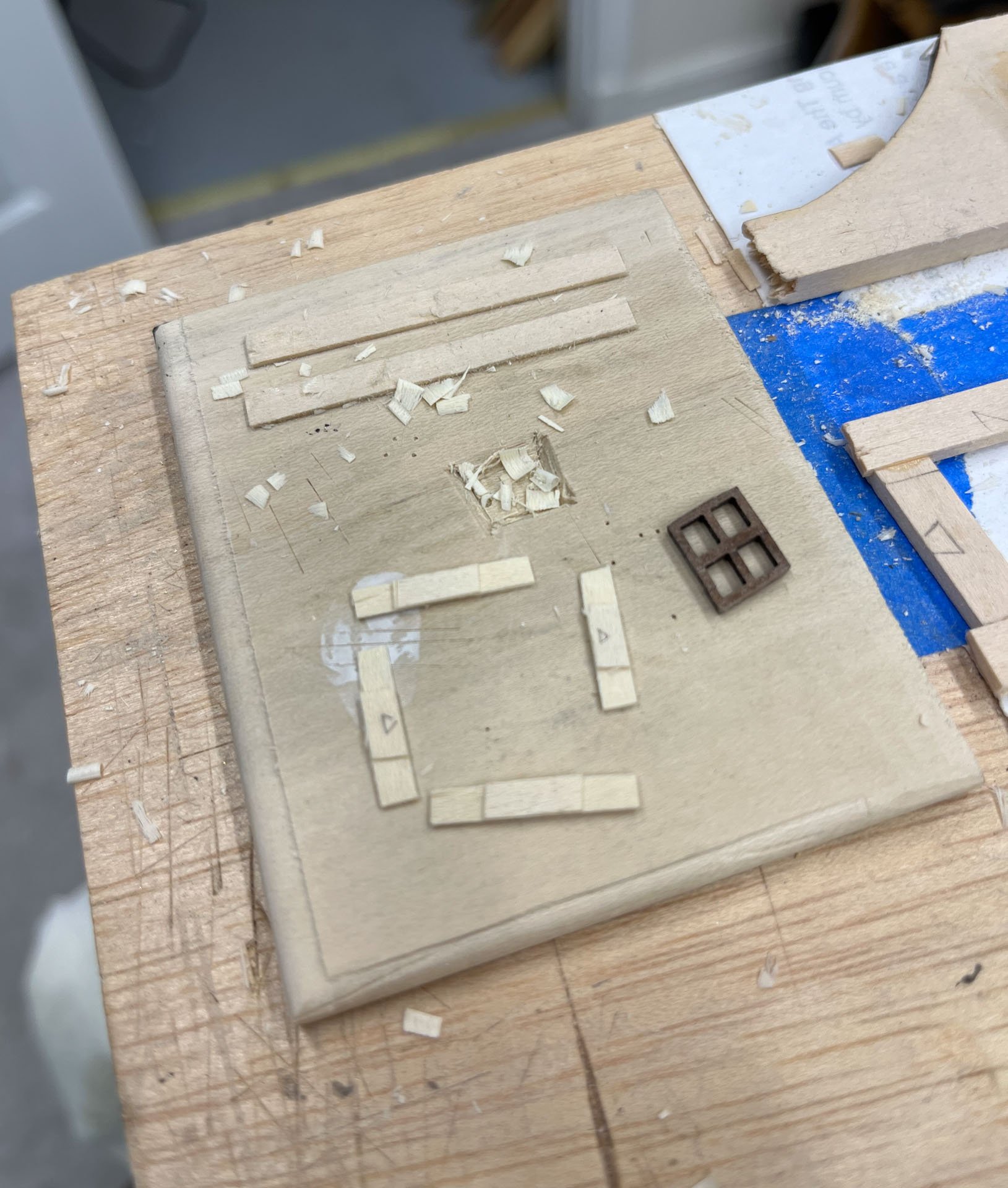
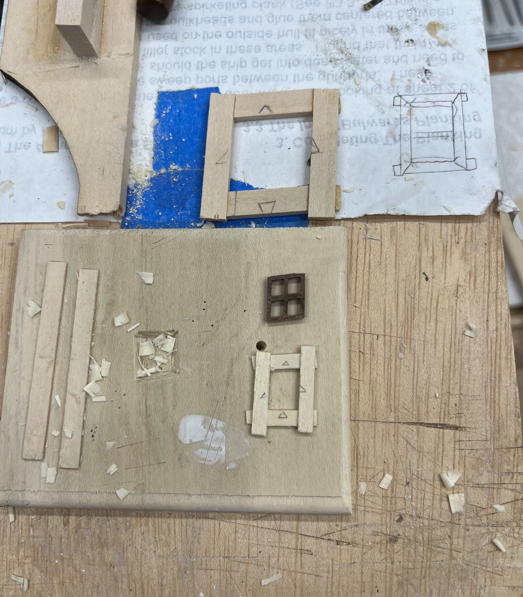
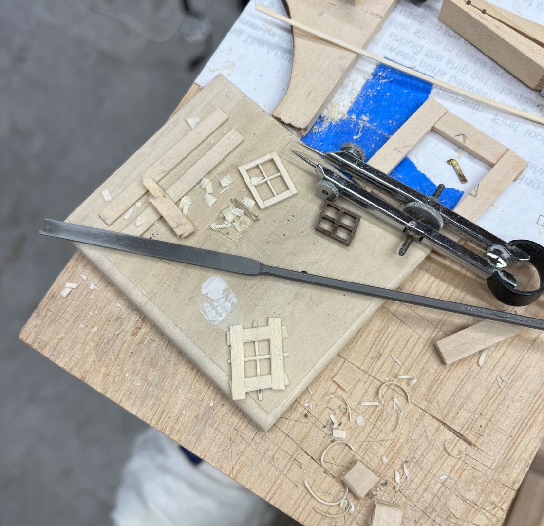
Happy Saturday afternoon MSW. Today I continue trying to make windows. Last time I made an oversized practice window which below I have trimmed down and I think it looks ok. Here are my 2 oversized test windows and the kit walnut one. This time around I made a new window the correct size although its still a practice version. First off I copied the angle of an outside window and made a cutting jig, similar to what I did with my mitered coamings. I used a large chisel initially but later used the largest of the 3 mini veritas chisels and it worked fine too. Everything is very oversize to be trimmed down at the end. The most difficult part wasn't cutting the angled lap joint, it was making the 2 opposite pieces of frame the same size. Still working on the best way to mark this. One other challenge is figuring out which direction the angled miters are cut. Doodling pictures did not help me visualize; I bet if I had worked in Sketchup I would have eventually gotten it but thats even more free time gone. It turns out if you cut all the angled joints on the right side of the above jig it makes the Left-side window (because I wanted the side members of the window (stiles?) to run all the way up/down. Presumably when I cut the joints with with mirror image left side of the jig it will make the right-side window. I formed the half-laps same as last post, which led to: I marked the frame with triangles and then put it together with Elmers white glue. Once it was dry I flipped it over and used a compass to determine the centerpoint of each side and then the big chisel to score a mark across the frame, then gently chiseled out the score to a V shape. I purchased the smallest Vallorbe rectangular file I could find which turned out to be 2/64" thick. I used this to file the V cuts into square. Despite the tiny size it still makes the rabbits look too big. But this is a test window so I soldiered on. I added one window muntin. Cut to fit the size of the slot its noticeably thicker than the previous test window muntin. Once it dried I filed the transverse slot and added its muntin. And once that was dry I trimmed the window frame down to its proper size. I thinned the muntins by filing then equally each side which worked pretty well. The window is surprisingly rigid considering how tiny it is. And here is the new window overlaid onto the left side of the stern, kit window on the right for comparison. It looks like I need the thin the frame edges even more but I am planning on adding some exterior window trim pieces which will take up some space. I have to enlarge the stern window openings at the top some and I think I will put backers in on the top and bottom where there is a little more room. Next up adding some window trim and deciding if I keep the muntin angles like the kit or change them so they follow the curve of the stern planking. Or something inbetween. thanks for reading Cisco


-
your gunport standardization and lining techniques are excellent. keep up the informative posts
-
Finally another AVS build! Looks good so far. In terms of hull planking I used the thicker basswood base layer as practice. the second thin layer went much better due to all the Learning that went into the first layer. In Clayton Feldman's book (the original builder of this model) I believe he only used 1 layer of hull planking so you could simply skip the walnut. either way I look forward to your progress. cisco
-
Y’now if you had used… sorry wont do that. in all seriousness i am amazed by your computer skills and how you managed to loft and produce an accurate frame. did you cut the stem pieces with the laser or by hand?