
CiscoH
-
Posts
384 -
Joined
-
Last visited
Content Type
Profiles
Forums
Gallery
Events
Everything posted by CiscoH
-
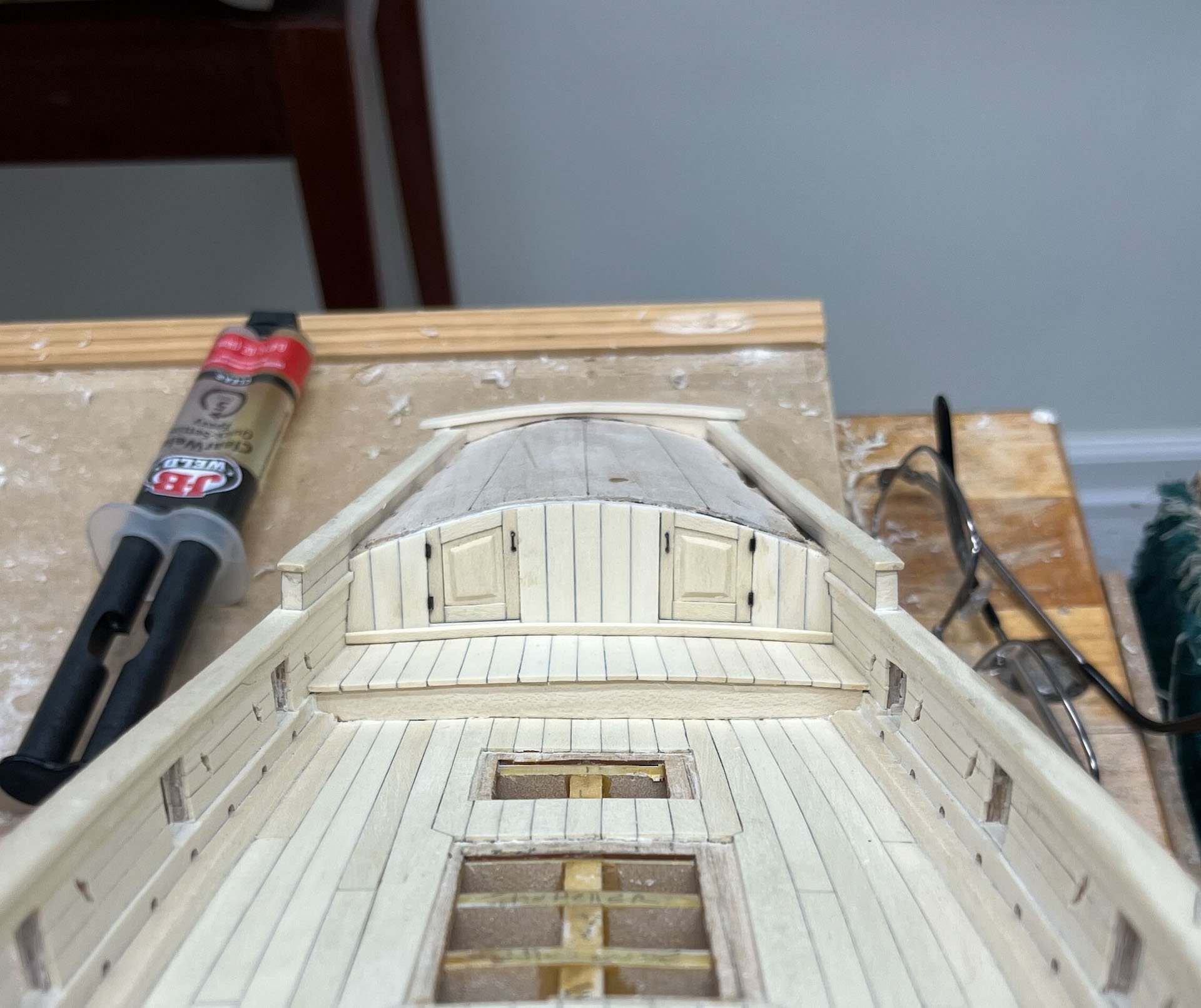
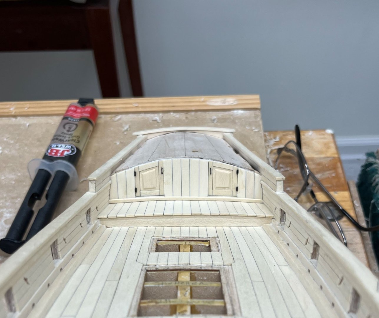
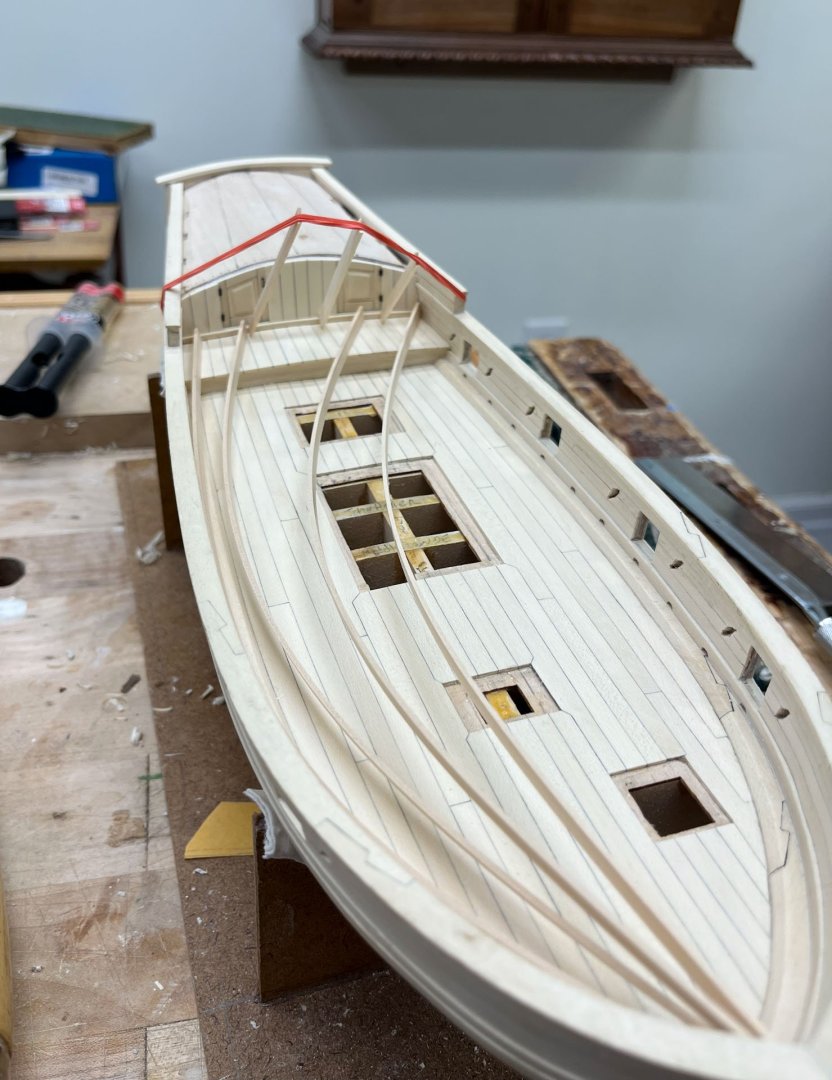
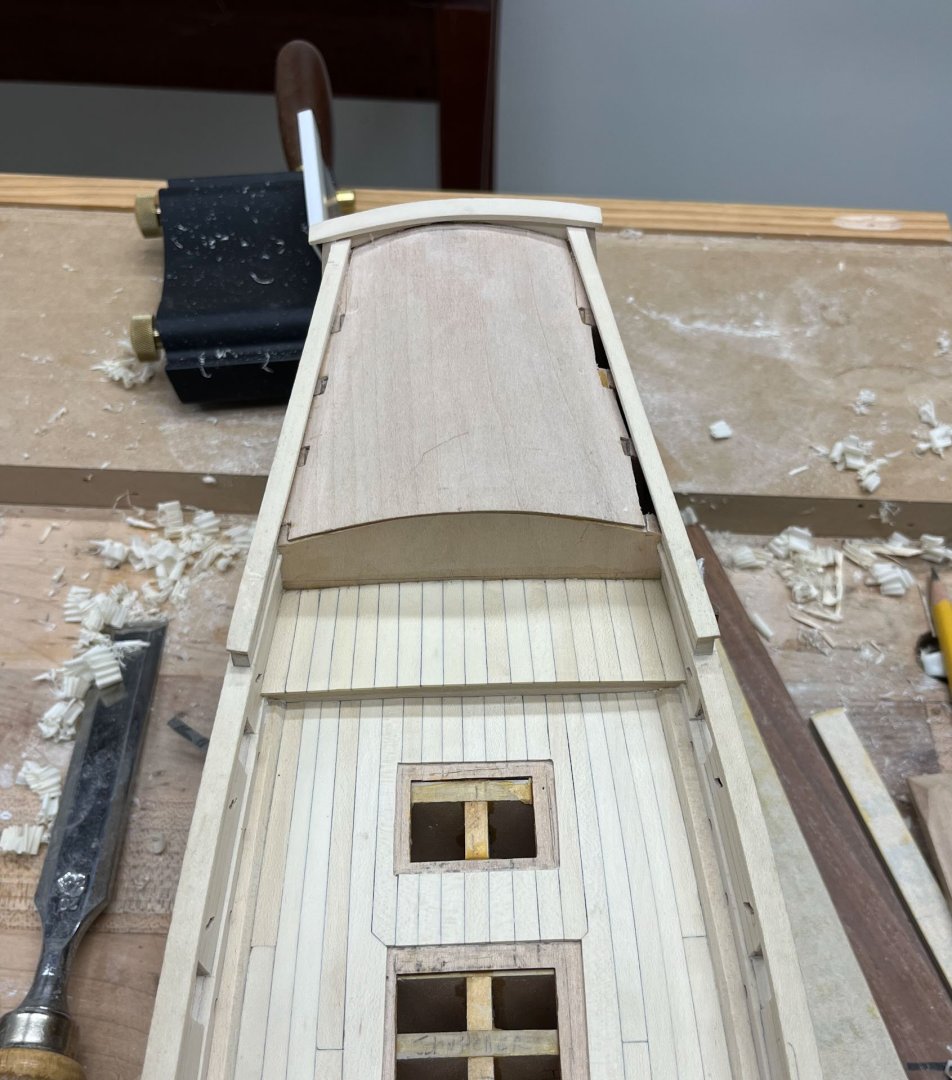
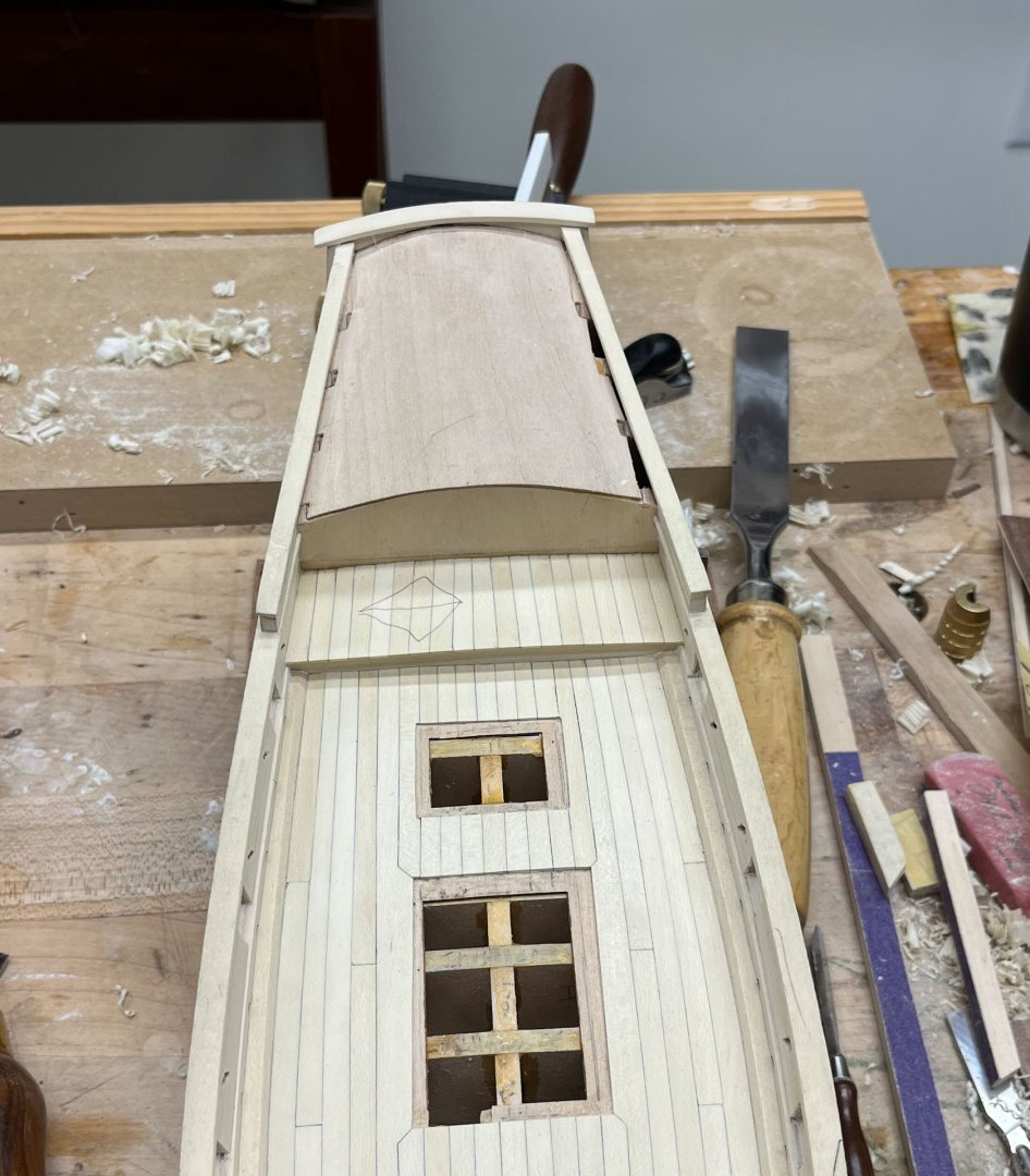
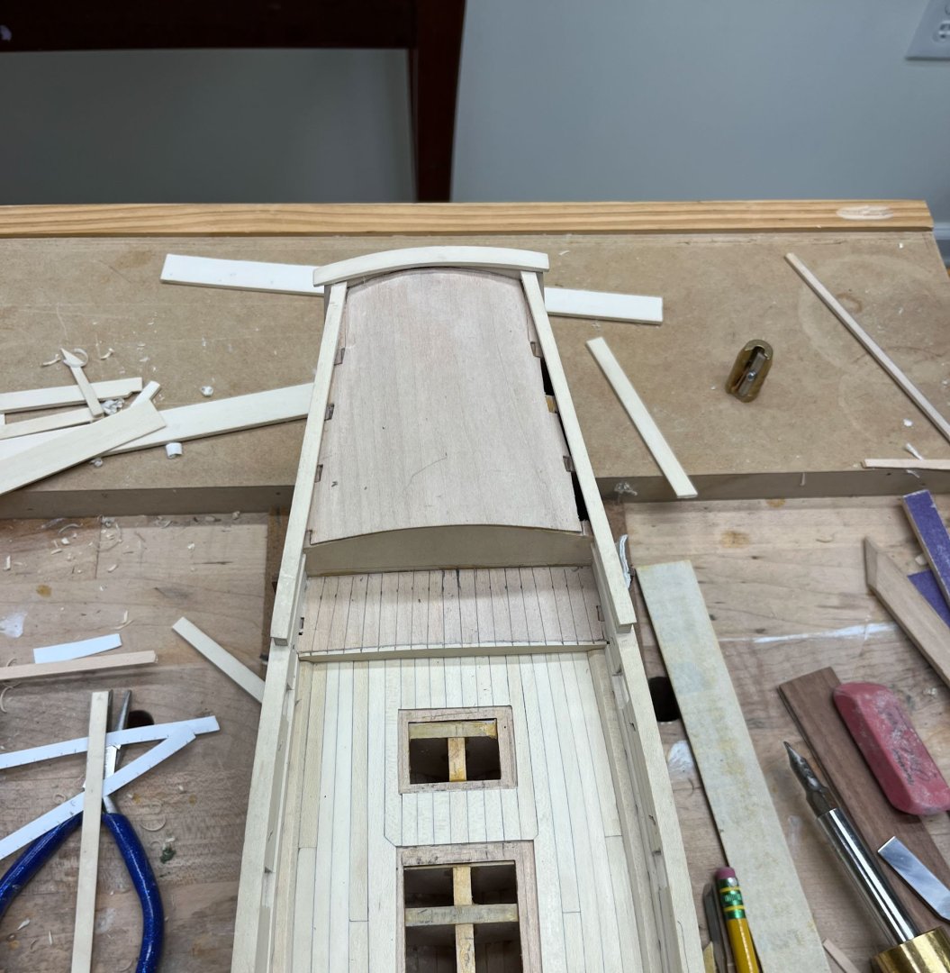
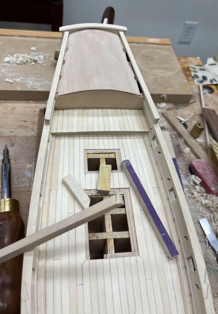
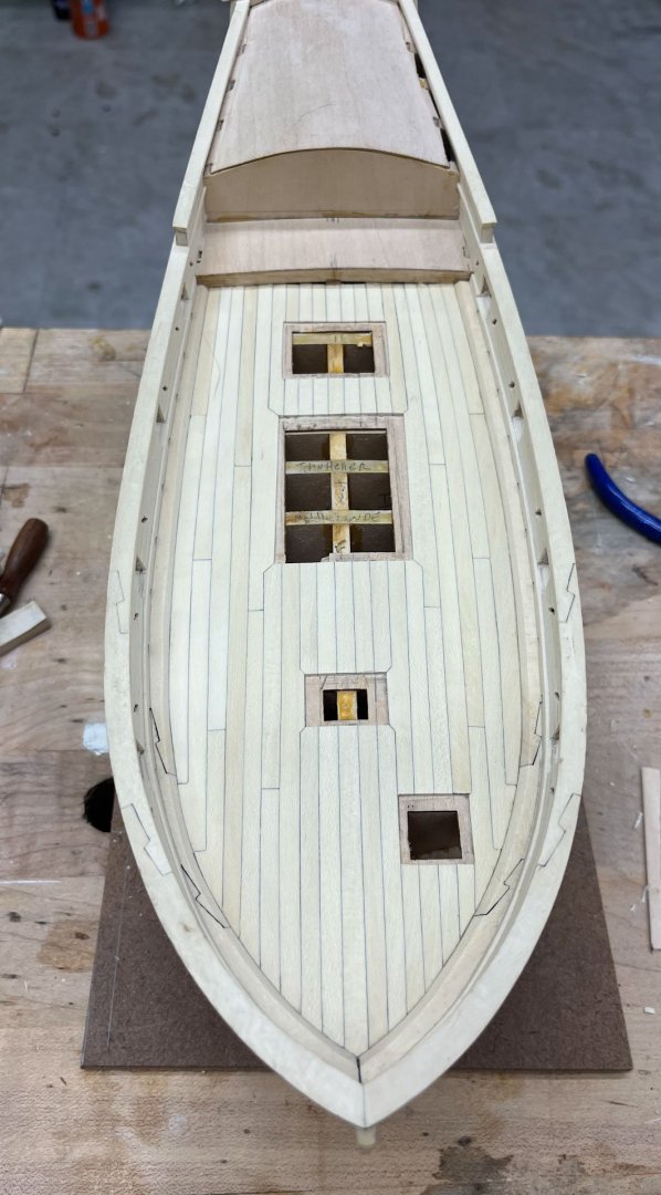
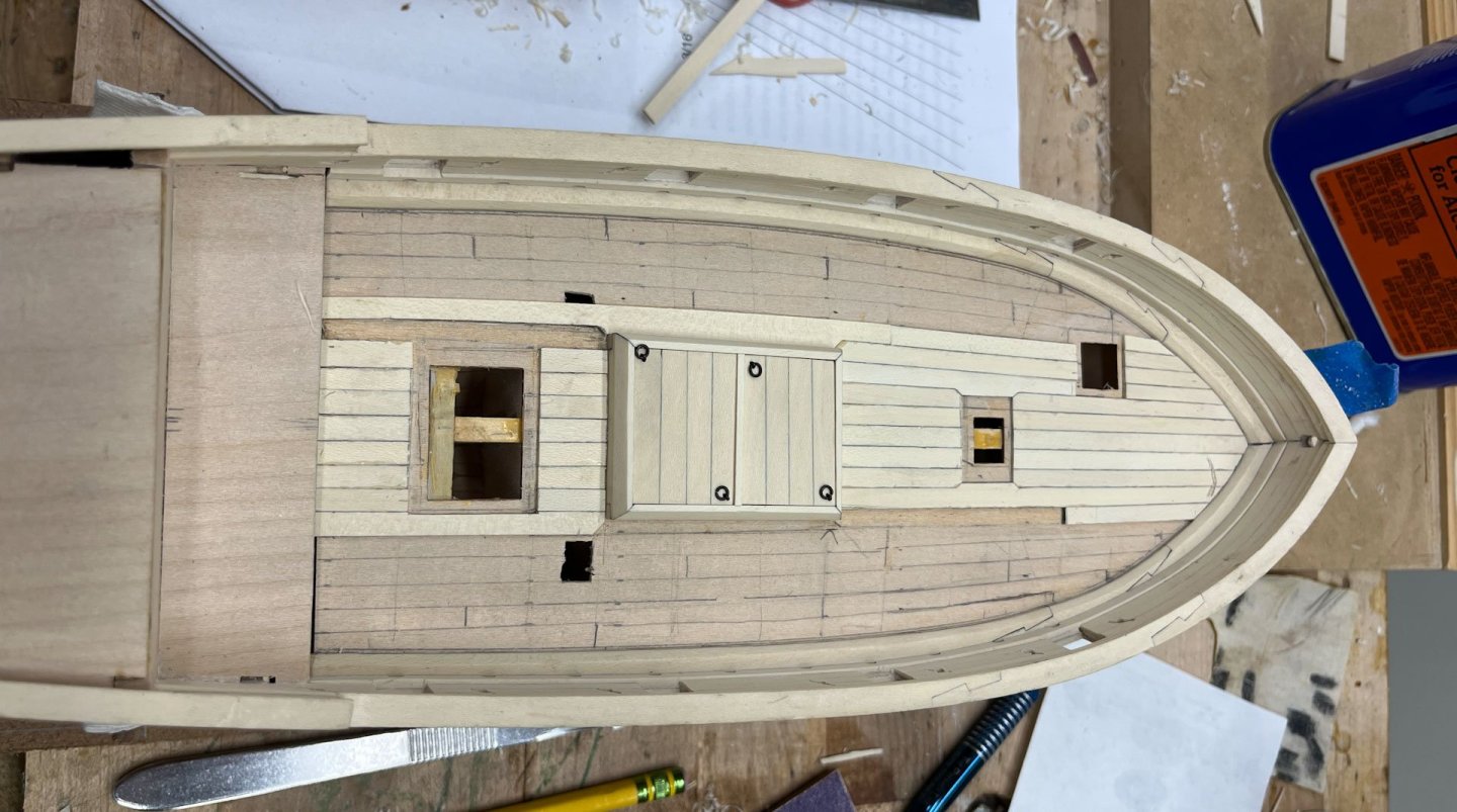
 I removed all the rubber bands and go-sticks and got a better photo this morning. The raised panels have a bit of a rustic look but I'll take it and moving on to the roof decking. Happy Sunday all Cisco
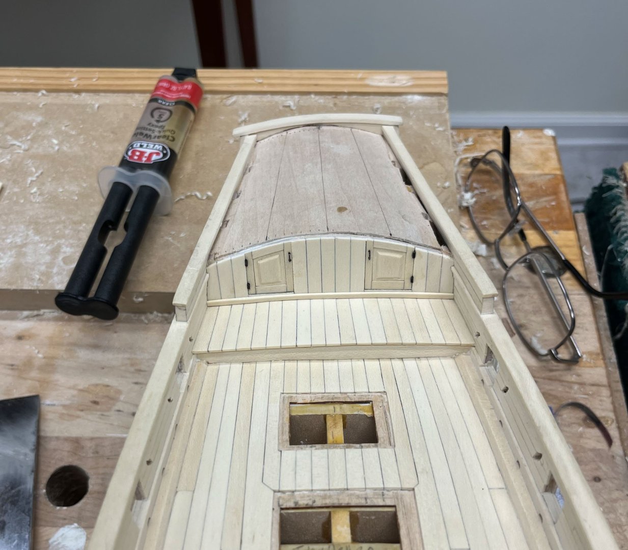
-
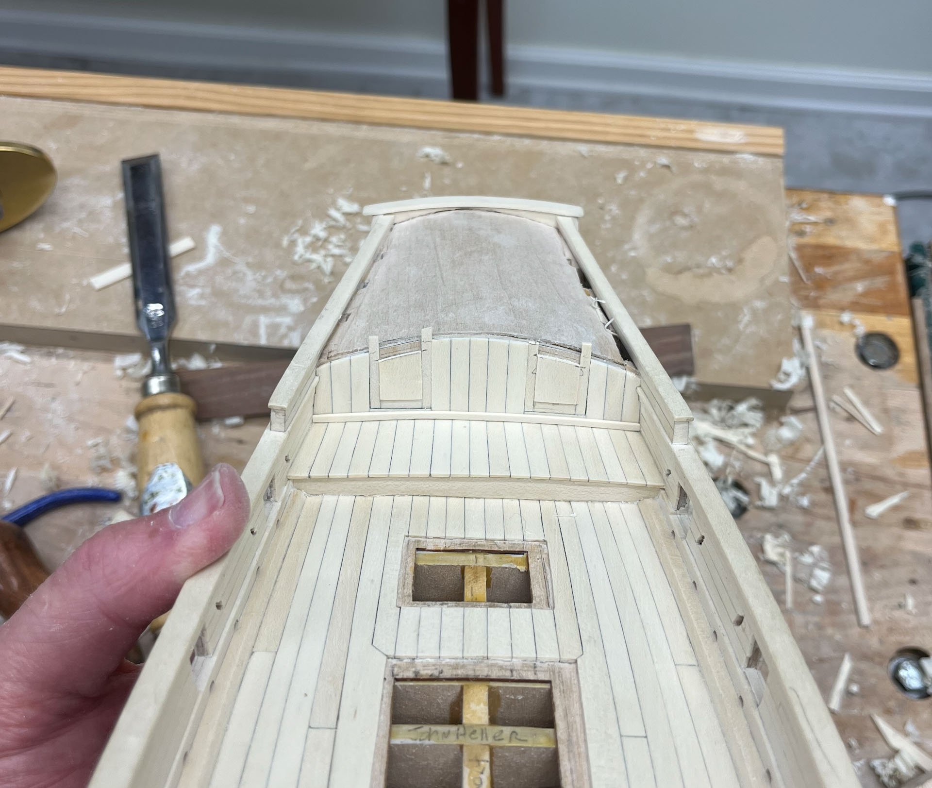
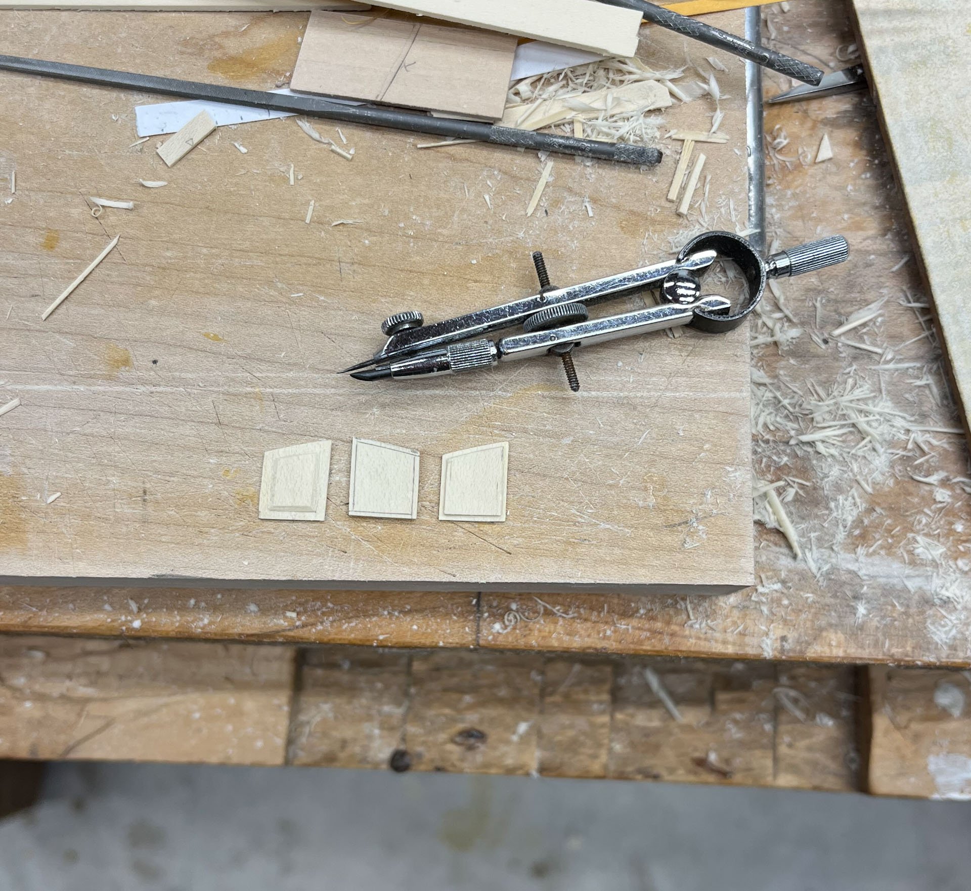
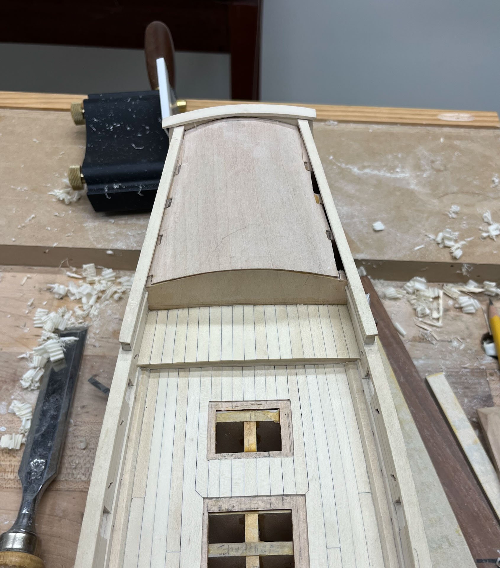
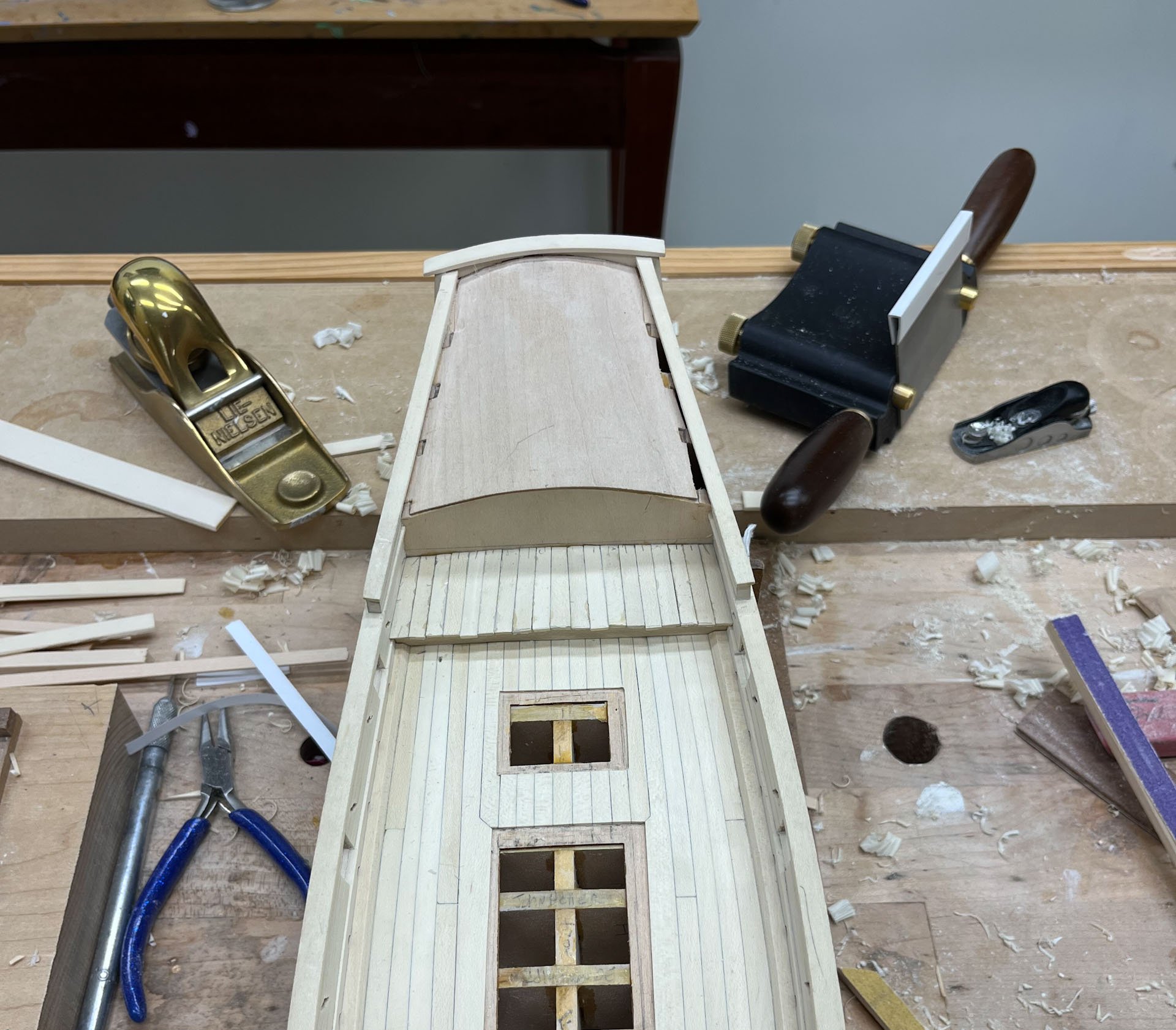
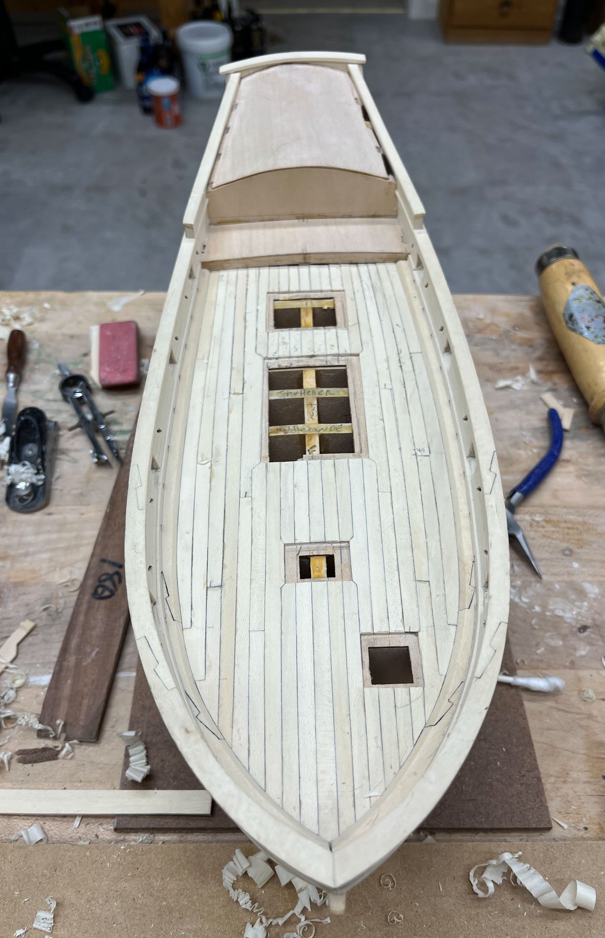
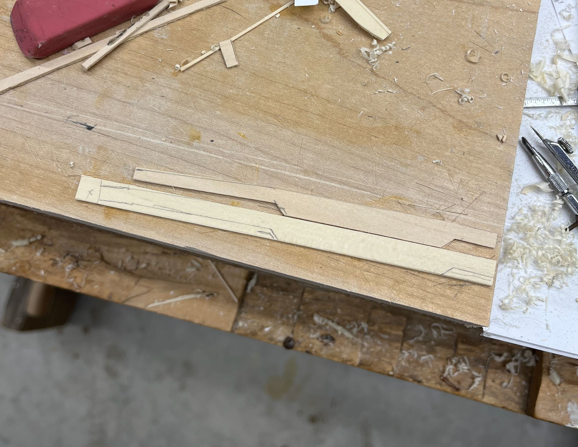
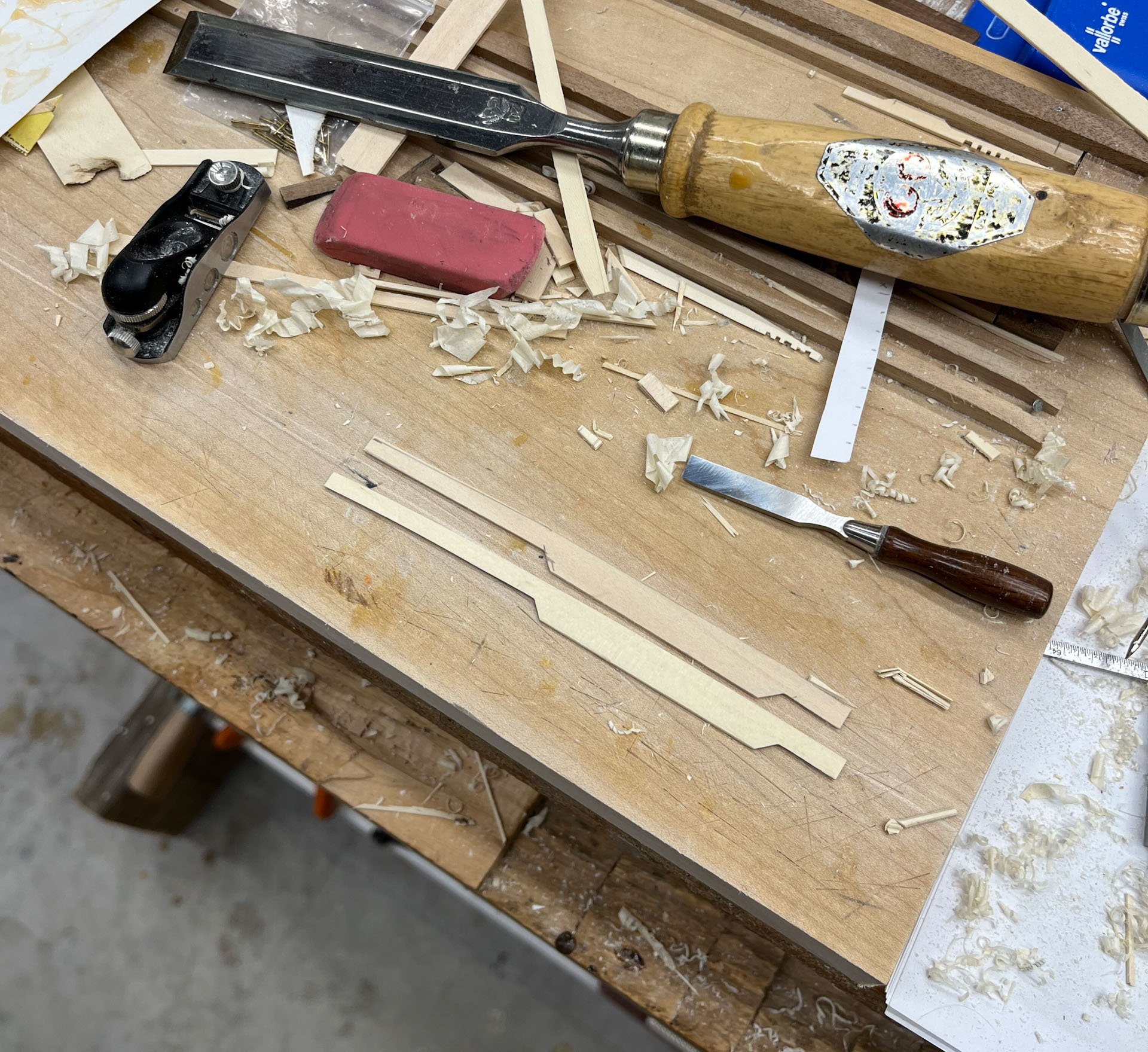
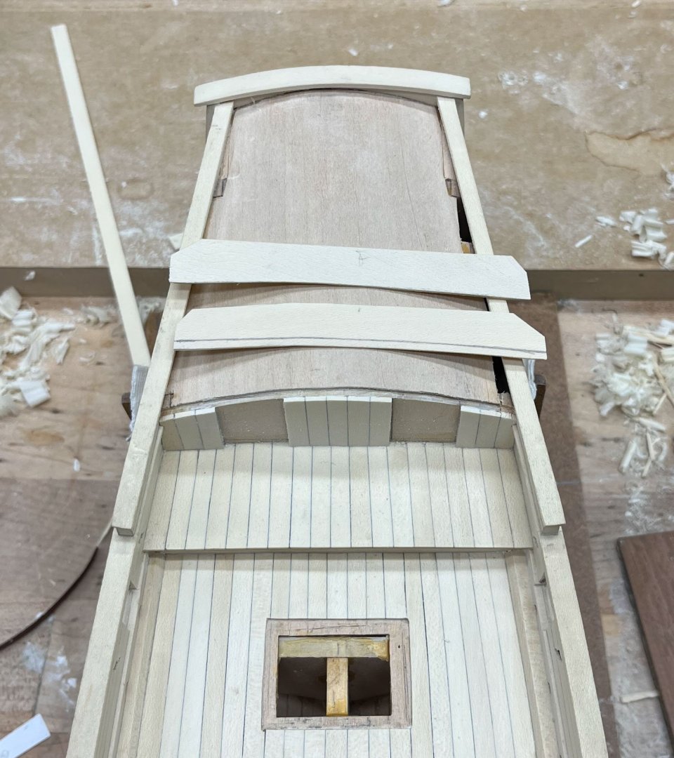
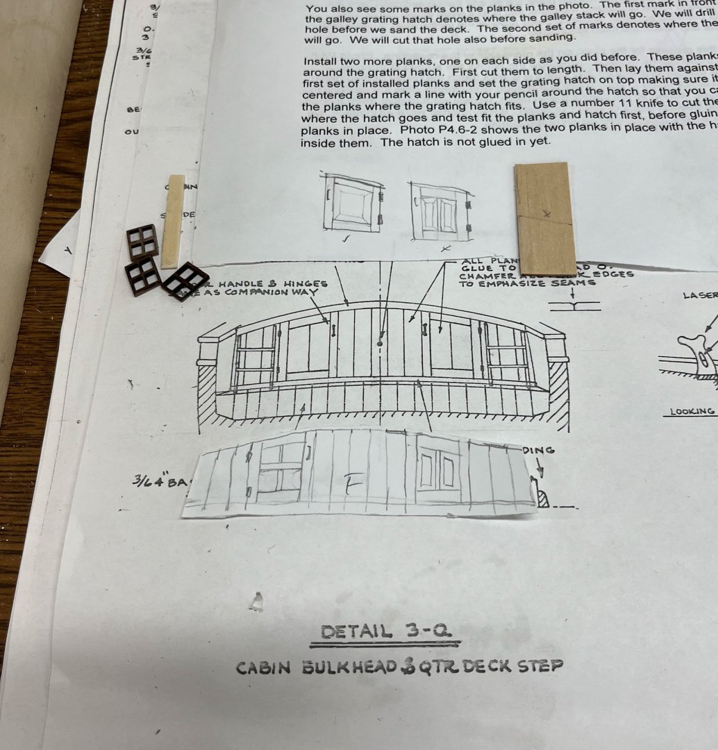
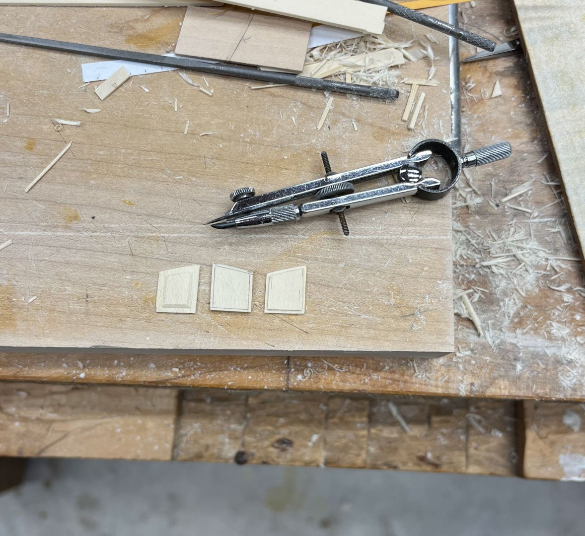
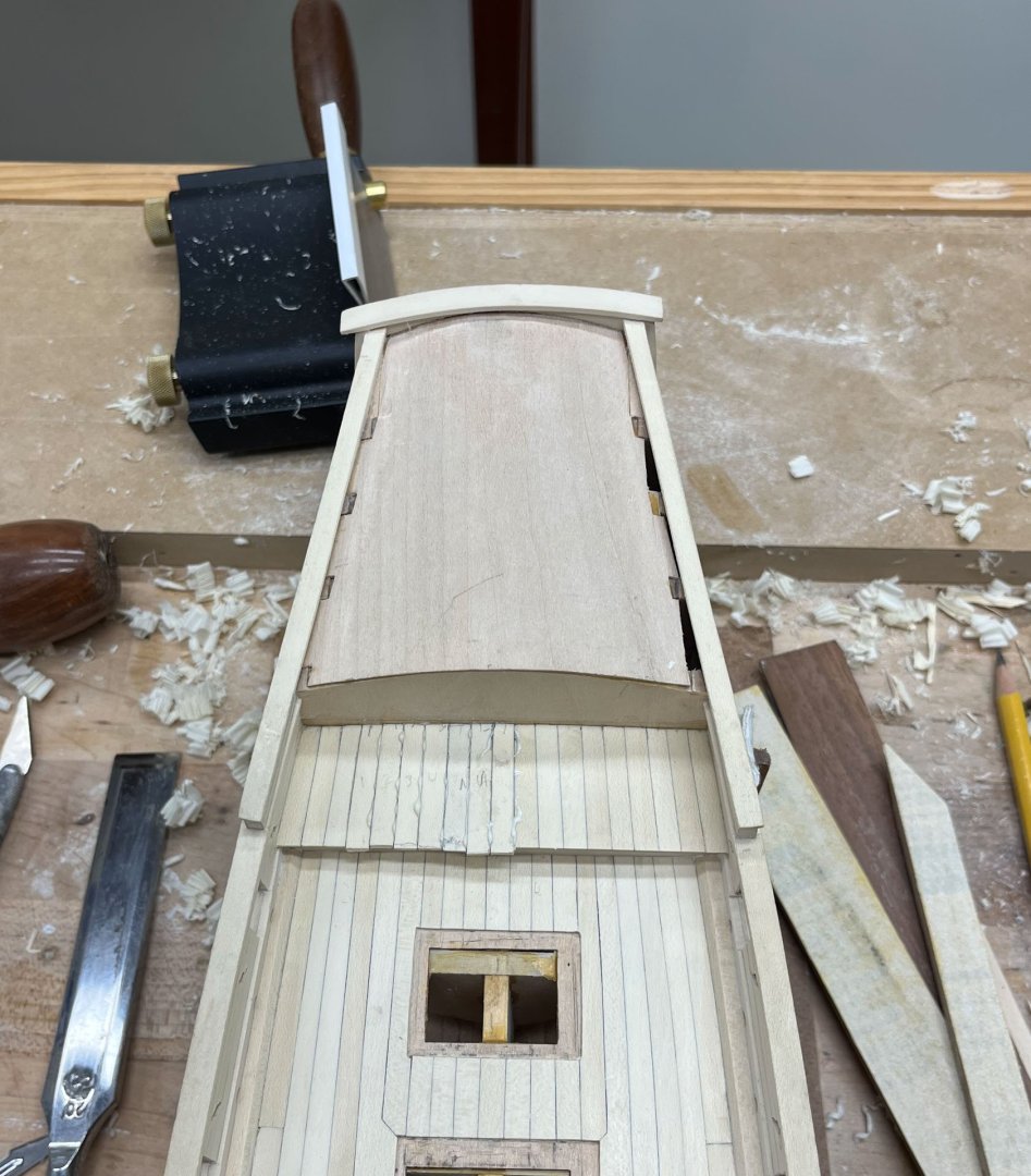
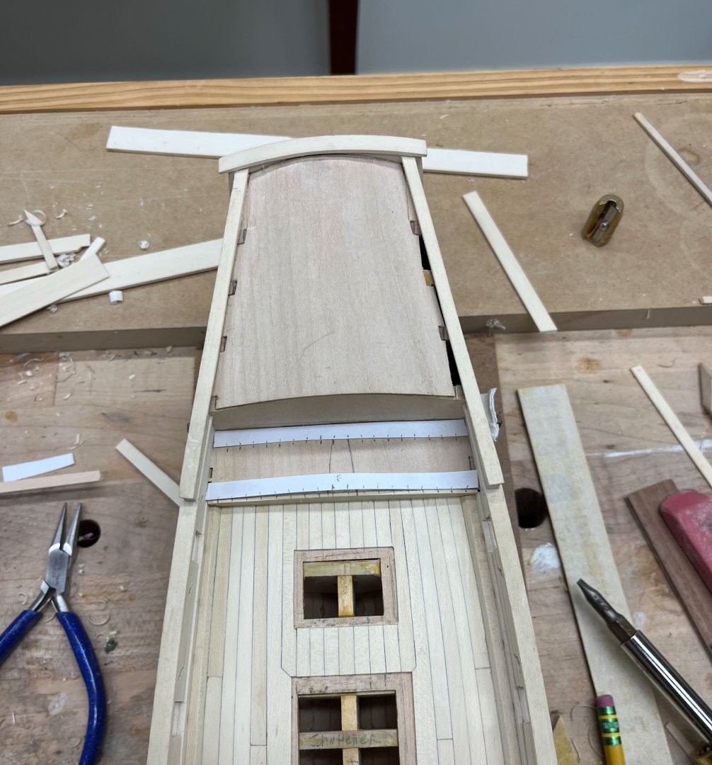
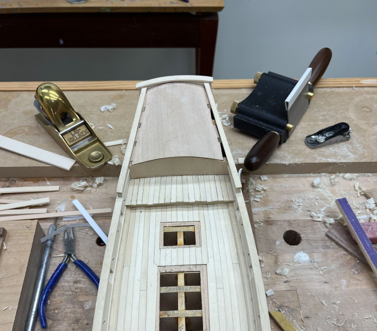
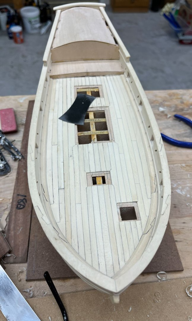
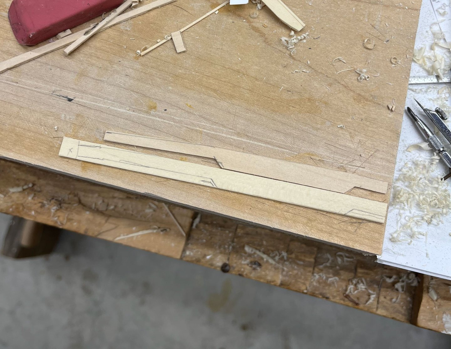
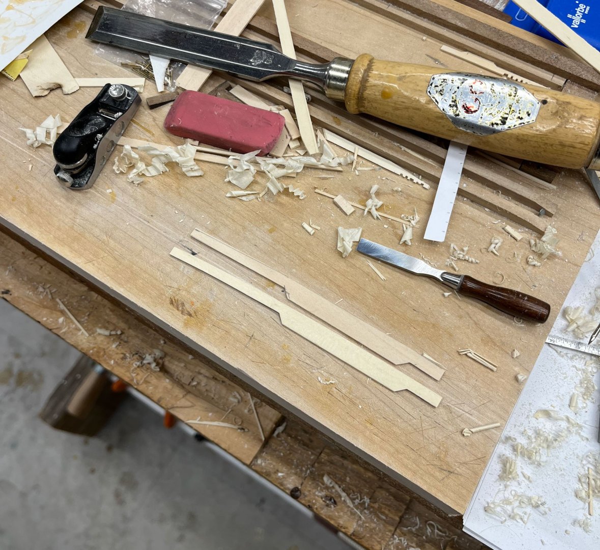
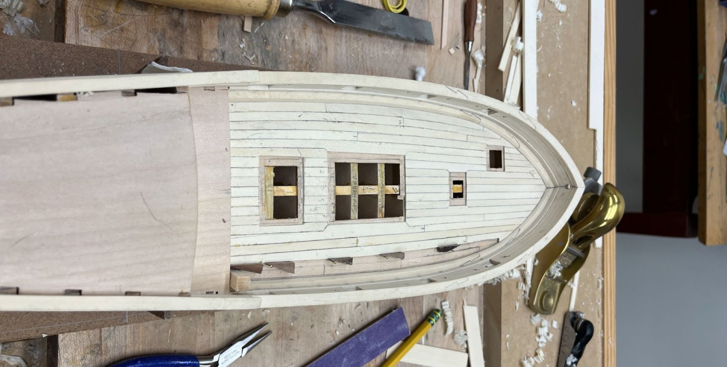
Well its been over a month. Vacation and work took their toll. I'm trying to bring my AVS up to the Joint Clubs conference as an "in progress" so now its crunch time. While anything beyond deck furniture won't happen in time; I don't want any basswood showing. Next up is planking the cabin entryway. Below is the kit door picture. I tossed around how I could make the doors more aggravating to build- maybe a window in the top of each one? maybe double raised panels? After looking at my drawings I eventually decided a single raised panel looked better than any of my other wacky ideas. The door frames were simple butt joints, highlighted with pencil. If I had more time the half-lap joints I used for the companionway coaming would have been sturdier to work with. But they turned out ok and were very solid once glued onto the basswood underlayment. For anyone who noticed I deliberately made the door frames inset so they would stand out. In reality this would have made the doors only open 90 degrees and been a pain to traverse but in this built artistic license overcomes functionality. Next I test-fitted my raised panels. The panels were challenging due to the flat reveal around the raised portion. It took a few tries. I scribed around the edges for a rabbit (shown below), then scribed further back for the borders of the raised portion of the panel. Tricky work although you are essentially cutting to a line. I don't know how I functioned before discovering my fine drafting compass. After planking the sides and middle of the cabin entryway I made the small base trim piece. Its fragile; I first made a "pretty close" version out of basswood (top piece), then a second try with holly. Once I got the bottom scribed as closely as possible I used the above compass to trace the width I wanted and cut it out. Then I attempted not to throw the base molding out (it looked exactly like cutoff scrap). Then I glued the top part of the door frame in, final fit my raised panels and glued them in. I forgot to say I pre-finished the door frames and panels, and pre-drilled for the handle and hinges before the frames were glued on; much easier to do that stuff on the bench. The handle and hinges were added with a touch of epoxy, then I used the below scheme of go-sticks and rubber bands to keep the basemolding in place while its glue dried. Sorry I now realize that pic is a little out of focus. Well thats progress as of now. This week I will be making the narrow planking to cover the roof of the cabin. And if all goes well I'll bring her to the conference for laudits and critique. thanks for reading Cisco

-
Simply Beautiful lines Siggi.
-
nice smooth curve of your bulwarks. looks very good. be aware that black Sharpies fade to a dull grey in about a year. i stopped using them as interplank tarring; paint, coloured paper, or pencil are usually coulourfast
-
Great discussion Mike. i like your last picture - it made me wonder which hand you took it with
- 969 replies
-
- 2
-

-
- hahn
- oliver cromwell
- (and 1 more)
-
Well OCD (and a gentle shove from BE, thank you Sir) won out. I redid the quarterdeck. Here's the finished version of Quarterdeck #1. The starboard side is too uneven to leave be. I marked the offending planks. I ended up taking the center plank as well. I had purposefully made it wedge shaped so each side could fan out and I think I made the fore end too fat. Next some alcohol applied with a q-tip and gentle chiseling. The strips came out fine; at this point I am depressingly skillful at errant plank removal. I made some new planks (and did a better job getting them equal with the Inlay Thicknesser), redrew my planking lines, and then fitted all but the center plank. Last time I glued in the planks one at a time which seemed logical, but once its glued in you are committed. THIS TIME I placed all the planks in place, before glue, and thinned some of them until they looked more equal. It took several adjustments; a little extra width really shows up I guess because the planks are so short. Here are the new planks glued in place. Not so pretty. This round seemed to level really fast, to the point that the new planks were noticeably thicker when viewed from in front. I had to deliberately sand them thinner to make the edge even. And here is after 1 coat of poylurethane. To me the lines are much straighter; ironically I don't notice the lines really now, whereas the last effort the crookedness really stood out. Alright I'm glad I fixed that. Looks much better now. Ok, on to the cabin facade and doors. thanks for reading cisco
-
Brig Le FAVORI 1806 by KORTES - 1:55
CiscoH replied to KORTES's topic in - Build logs for subjects built 1801 - 1850
very nice as always Kortes -
Good Tuesday evening all In today's post I am planking the quarterdeck; all 2 feet of it. I wanted a fan-shaped pattern of decking which as you'll see didn't work out as well as I'd hoped. I also wanted to try out my Veritas Inlay Thicknesser. When I lay in the main deck my wood pieces started out a lot of different thicknesses. I used my mini-plane to roughly make them the same, but as I ran short of acceptable planks I used a few that were significantly thinner. It was much harder to bring the surrounding thicker planks down to the level of the thin ones and led to some unevenness of the deck which you can't really see but can feel if you run your fingers across it. So how to get planking that was the same thickness without the tedium of hand planing or scraping each piece and measuring every 2 inches with a caliper? (and no for now I am not buying any powered devices. I want to learn to do it by hand first). I had bought the Inlay thicknesser a while ago but it had to be sharpened which was Work so I had put it off. No longer! The instructions have you make all the planks all the exact same width, except the 2 side ones trapezoid to fit the last uneven space to the hull bulwarks. My eye was always drawn to these edge planks as looking uneven so I tried a fan pattern. (The Fore part of the quarterdeck is slightly wider across than the Aft portion.) First I broke out my tick strips and measured the front and back of the tiny quarterdeck. Then I drew in lines for each plank. This looked slightly wonky to my eye but I figured I could adjust the lines some as I put in each plank to make them look more regular. A lesson here - if the plan is off and you accurately build to the plan then the build will be off too. I should have redrawn some of those lines. Now to make even thickness planking. I quickly discovered the Inlay thicknesser couldn't remove much wood at a time. It worked best when you shave the stock to Almost Thin Enough with the miniplane, then use the scraper to bring it to final thickness. The planks weren't perfectly the same thickness but they were a lot closer than before. I added all the planking one at a time and used a pencil to indicate caulking and yellow glue, same as before. Here it is before sanding and evening the edge: And here I have sanded it flat (180 -> 220 grit), leveled the edge, and removed some glue squeezeout that formed underneath the overhang (which was a pain to get at), and applied 1 coat of water polyurethane. I put all the oddly-shaped sanding blocks I used onto the deck so i remember them in the future. It looks ... ok. My fan shape didn't "fan" very well. I like the port side but I may replace some the middle starboard planks with better shaped ones. The wheel assembly goes directly on this deck so it will probably hide things but I'll have to see what my OCD does overnight. Your eye really picks out Not Parallel lines. Well once thats resolved next up is the entrance facade to the cabin. I'm thinking flat paneled doors are boring; maybe doors with lower raised panels and upper windows? thats it for tonight, thanks for reading, Cisco
-
Brig Le FAVORI 1806 by KORTES - 1:55
CiscoH replied to KORTES's topic in - Build logs for subjects built 1801 - 1850
Glad youre back Kortes! Lovely work -
Beautiful planking Siggi!
-
Any pictures of the carving process? you got a very clean bead on a curved surface going 90 degrees to the grain, which is pretty impressive.
-
I think it took me 3 months to plank my hull. Amazing job Mr Ensign it looks fantastic
- 332 replies
-
- 2
-

-
- Harpy
- Vanguard Models
- (and 1 more)
-
can you post a picture of what youre trying to do? that would get you better answers
-
Good Evening MSW! Here in Delaware its snowing like crazy. Time for Main Deck Planking update #3. I got the last main deck planks in. No new surprises once the hooked ones were fitted. Only sad part is all the deck furniture will hide most of it. Here's the initial finished state. Some glue smudges, a lot of pencil marks, and the uneven thicknessed planks make it look pretty rough. I tried using this tiny scraper I got a while ago. It works surprisingly well - no tearout atall and it did the port side of the deck great. But after a lot of tiny shavings and not much progress leveling the more uneven planks on the starboard side I switched to small blocks of wood with 180 grit sandpaper. That got it leveled fine, so i switched to 220 grit, vacuum again, and first coat of water based polyurethane. I'll do another coat of polyurethane tomorrow and then move onto the cabin planking. thanks for reading Cisco

-
so this was your first build? i dont know which is more amazing; the quality of the ship and especially the carvings, or the fact you stuck with it for 25+ years. The natural edged wooden shelf and carved cradles work very well with the finished model too. Amazing job!
-
i went through the same struggle making the joints on my AVS stem. Every time i sanded the joint it changed the angles of the parts. You could have tight-ish joints but the stem off the lines on the plans, or the opposite, but not both. your job looks great
-
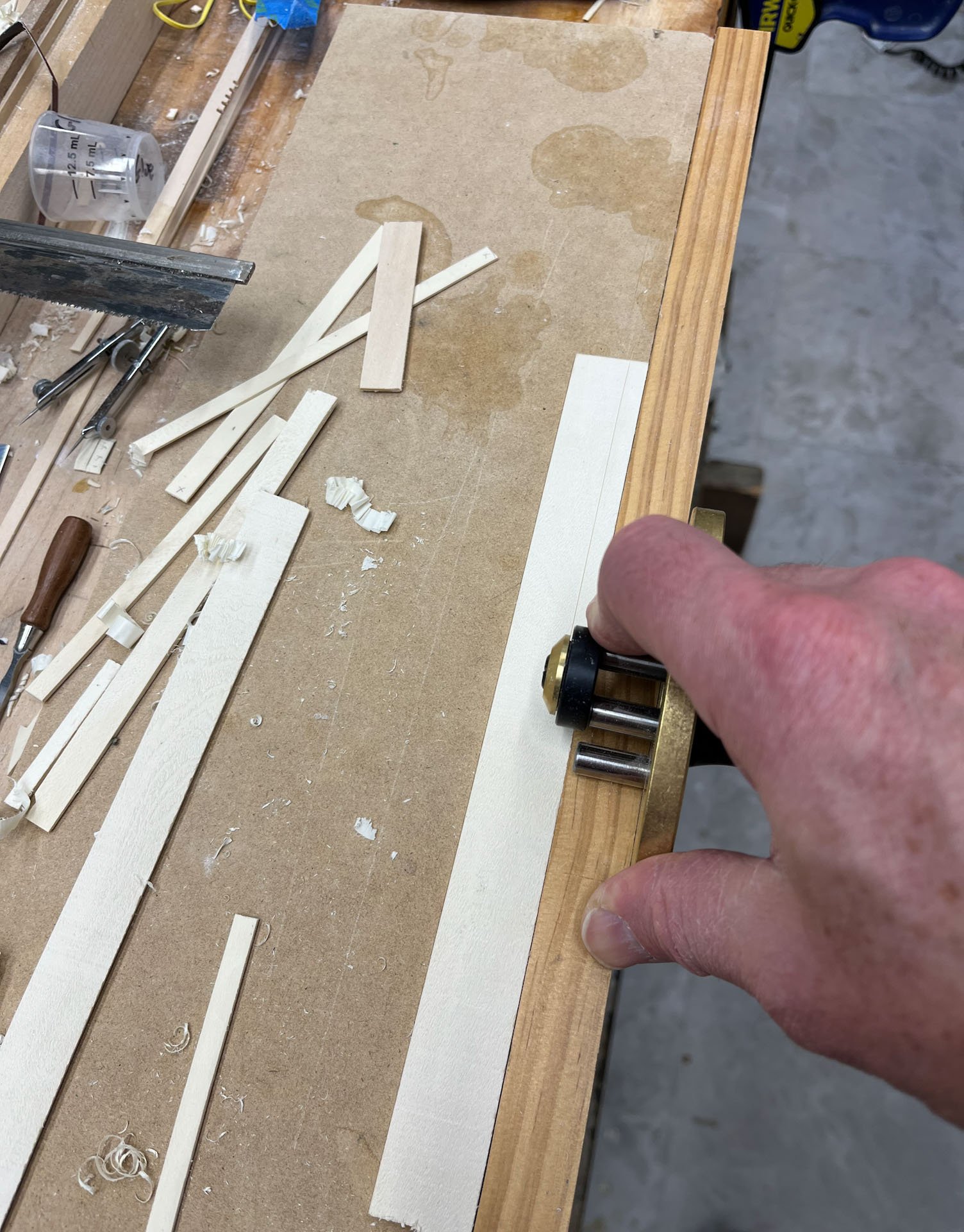
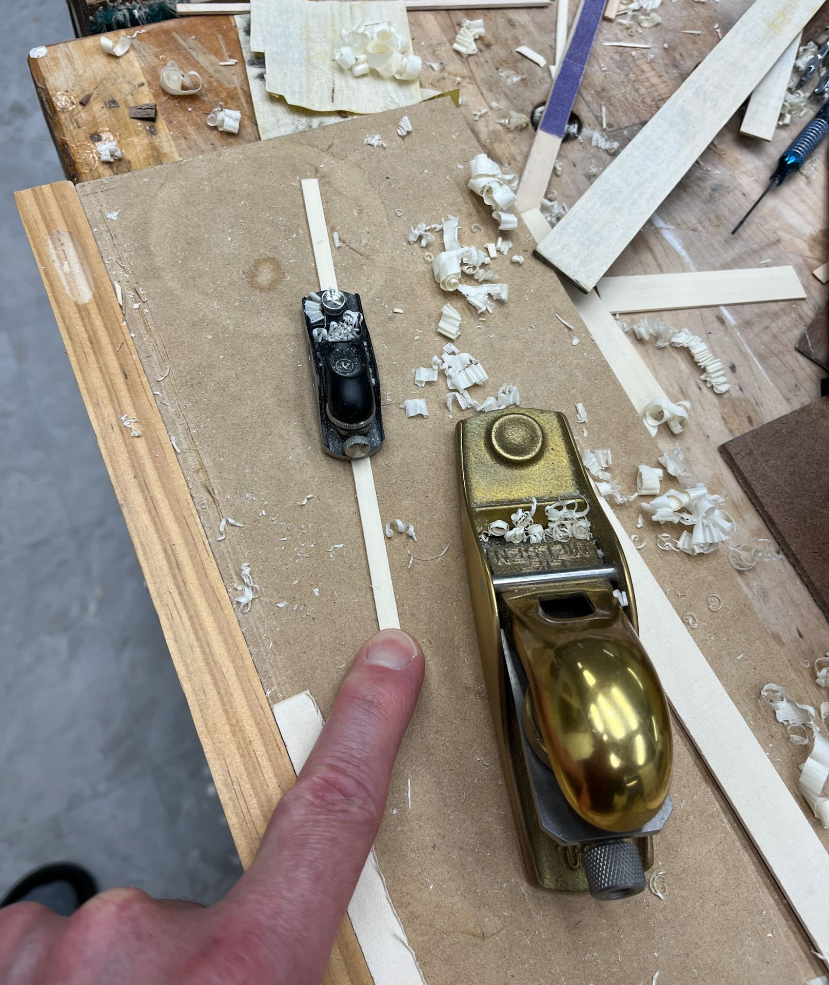
Thanks Hamilton. The bigger brass plane is from LieNielsen, the tiny one is from LeeValley. The marking tool is also Lee Valley- a string inlay cutter. Very heavy duty and astoundingly cheap at 115$. I use it and the tiny handplane (and their mini chisels) all the time. https://www.leevalley.com/en-us/shop/tools/hand-tools/inlay-and-veneering-tools/69874-veritas-string-inlay-tool-system
-
beautiful planking job
-
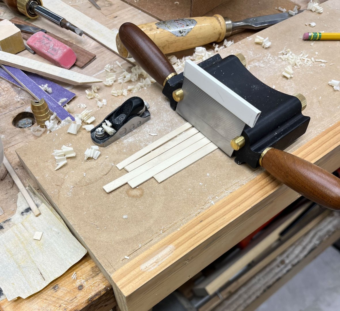
Good Sunday evening MSW. Another plank-the-deck update. I thought I'd recap my plank preparation technique. I have 2 billets of holly that I have cut aprox 1/8" thick slices from. These are rough on both sides and too thick to directly plank with. I don't have any sanding or thicknessing machines (and regardless prefer to do it by hand anyway). To cut my planks I use the below device to slice off a strip a bit wider than what I need. I really like being able to control how wide my planks are, as opposed to getting pre-cut planks that are all uniform. After cutting off a plank I thickness it with my handplanes; basically a few strokes on either side to remove the roughness of the bandsaw. Holly seems to be very forgiving and gives a glass-smooth surface even going against the grain if the tool is sharp. I hold the one end with my finger while planing; it pays to leave the strip long to start so you have more to grab onto. Both edges are planed in the same manner to get them pretty close to square; I also use sandpaper attached to thin strips of wood for final shaping. The long straight planks are easy. The tough ones are the wide miters and the hooked scarfs. After several holly discards I started making the weird shapes out of scraps first. This one was especially tough- a mitered section incorporated into an overall curved plank. But once I got the test piece done it was easy (well, a little easier) to trace it onto my holly stock and trim it close, then fine tune the fit. And here it the final holly piece after fitting. I hope it can be seen the whole plank curves as well, so you have to fit the 2 miters while fitting the curved section. I found it plenty challenging. And below is that piece glued in place on the port side of the main hatchway. But. As I mentioned before my main hatchway is a trapezoid, not a rectangle. I kept getting gaps that were driving me knutts until I turned the main hatchway 180 degrees and it overall fit better. Except now the port back miter was off a little so in the below picture I have removed the offending plank and once a new one was fitted it looked much better. But that now emphasized how off the rest were so the whole row of short planks clearly had to go. I think I've planked this deck 3 times by now. The miters around the main hatchway are (a little) different sizes but its as good as its gonna get; time to keep moving. And here's where we stand tonight. Some of you may be able to form planks perfectly so finger power alone holds them in place. I still like to place brass pins and wedges, like I did on the hull, to tighten up any "gaps." Once all the planking is in I will scrape it flat, then sand and finish it with water based polyurethane like the rest of the ship. Then its on to planking the cabin which will have NO HOOK SCARFS or MITERS. thanks for reading cisco


-
thank you Mark for the great descriptions. i have read many times that the sternworks and quarter galleries are not atall straighforward; your dissections are a great help puzzling out why
-
that stern lantern looks pretty darn good to me
-
USS Constitution by mtbediz - 1:76
CiscoH replied to mtbediz's topic in - Build logs for subjects built 1751 - 1800
i personally like the dark grey better. Maybe a mix of the 2 paints? -
Mark your planking and explanations are great! keep up the good work cisco
-
Fascinating Dan! thank you for posting all your research. i visited the barge in its museum a few years ago and you really have to see it to appreciate how enormous the whole thing was. hard to believe it was laced together