


Mahuna
-
Posts
1,500 -
Joined
-
Last visited
Reputation Activity
-

 Mahuna reacted to davec in East Coast Oyster Sharpie 1880-1900 by davec - FINISHED - 1/16 scale
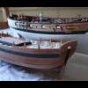
No log entries in two years, but I have been slowly plugging away a few minutes a week. I had a pretty steep learning curve silver soldering the brass fittings for the masts and figuring out how to make the mast hoops. Rope was made with Chuck Passaro’s rope rocket. Rigging relies heavily on John Leather's The Gaff Rig Handbook. When the book didn't have the necessary detail, I defaulted to the advice from the Mystic Seaport staff restoring their Sharpie - "These boats were built in people's backyards with what they could make or get from their local hardware store." I did not want to make sails and there is no rigging exerting downward pressure on the gaff, so rather than having limp rigging, I lowered the gaff as if a mainsail was about to be attached. Both kids were with their partner’s families this Christmas, so I got to spend some concentrated workshop time and finished this morning.
Next project is a case – I got some good tools for Christmas (router table, acrylic cutting table saw blade) so I should be able to build one. I made some acrylic shelves for my display case, so I’ve got the cutting and edge polishing down, and just need to sort out the gluing.
Happy New Year Everyone!
-
 Mahuna got a reaction from FrankWouts in HM Cutter Cheerful 1806 by Chuck - FINISHED - 1:48 scale - kit prototype
Hi Chuck:
I look forward to following your build. What differences do you experience between boxwood and pau marfim? I have some castello and pau marfim and haven't discovered a major difference between them.
Frank
-
 Mahuna got a reaction from thibaultron in Bend cast metal parts
I've used cast metal bird feet in my bird carvings, and they can be bent by warming them in boiling water, then CAREFULLY bending them to the position wanted. You might try this on your cast parts.
Frank
-
 Mahuna got a reaction from goatfarmer11 in Kathryn by Mahuna - FINISHED - 1:32 - Skipjack Based on HAER Drawings
Part 5 – The Stem Knee, Keel, and Worm Shoe
The stem knee supports the inner stem, has a 5” square socket to support the Sampson Post, and has a mortise on each side for the foreward-most frame. The following photo shows the stem knee drawing, which was mirrored for aligning the two sides of the knee.
A small chisel was used to cut the socket and the frame mortises into the stem knee. Because the knee was fairly small, I used the work setup shown in the following photos.
A 5” x 5” strip was used to check the accuracy of the socket for the Sampson Post.
The stem knee was then glued in place.
The rest of the keel (aft of the centerboard slot) was installed as two pieces. The first piece was installed at the beginning of the curve in the keelson.
The aft keel piece was formed from 3 separate timbers.
This aft piece was then glued in place.
This completed the Keelson/Keel assembly.
There is a ‘worm shoe’ installed under the keel, as a protection for the keel. This is made from pine and is only 2 “ thick. The following photo shows the worm shoe being installed.
The cutwater and outer stem were fabricated, but only temporarily installed at this point. The outer stem will cover the plank ends, and will be tapered from the planks down to the width of the cutwater, so this work will be left until the planking is installed. The profile of the outer stem has been cut, and holes have been drilled to allow the outer stem to be temporarily mounted to the inner stem. In addition, a slot was milled in the forward face of the outer stem for installation of the cutwater.
The following photo shows the completed Keelson / Keel / Stem assembly, with the temporary installation of the cutwater.
And, finally, mounts were created to keep the keel assembly at the proper height from the shipway, and the assembly was mounted to the shipway.
With the assembly now mounted in place, it’s time to start making and installing the frames for Kathryn.
Thanks everyone for following along, and especially for the Likes and comments.
-
 Mahuna got a reaction from Saburo in Chuck's carving attempts - #11 blades and micro chisels
Hi Chuck - great work.
If you have a rotary tool you could try using a small ceramic stone for final shaping. They're available in white, green, and pink. The white stones are the finest. All of these stones can be shaped using a small diamond sharpening stick, so you could bring them to a very fine point for getting into tight areas. Most of these stones have 3/32 shafts, rather than the 1/8 found on Dremel, and can be found in a wood carving supply site. They're used extensively by bird carvers and other power carvers. I can send you more info if you want.
-
Mahuna reacted to Thistle17 in Florida Sharpie Fishing Schooner of 1899 by Thistle17 - RESTORATION
One could have a healthy discussion about the precepts of restoration. When is a replacement part, made anew, but differently, yet retaining the functionaly to be considered an unfaithful reproduction. Well call it what you wish. I had to scrap the replacement chainplates. During install they were so delicate that the tip which was a piece of soldered tubing attached to the plate body separated in both accounts. The stress was just too great on this diminuitive part (just about 1mm). I had to remake them much as I and others made Cheerful chainplates. You can find this in Chapter 9 of the Cheerful build log. Basically the chain plate has a tang at its top that is bent into a loop that allows connection of the lower deadeye to the chain plate. In this model there are no deadeyes. There is a looped line that passes through a shackle attached to the formed eye of the bent over tang on the chain plate and the shroud eye to adjust tension.
Attached photo is the reconstructed chain plate with shroud lashing installed but not tied off. Tie off is identical to deadeyes.
It is no wonder why they were missing on the model when I got it. I will move on from here and not look back.
Joe
-
.thumb.jpeg.fc5d633a7b34428fcf19419a73d56d55.jpeg) Mahuna got a reaction from EricWilliamMarshall in Freezer Paper - an awesome tool
Mahuna got a reaction from EricWilliamMarshall in Freezer Paper - an awesome tool
Hi all;
An update on using freezer paper.
I left the freezer paper cutouts of the bulkheads on the plywood since I posted the photo (4 days ago) because I had to leave on a business trip. When I picked them up today I could see the paper was separating from the wood and not adhering very well. This isn't a surprise, since I expect that the wax will revert to its normal consistency after a short while.
The lesson learned is simple - for best results, cut the wood as soon as possible after applying the freezer paper template. Still better than messing with glue!
Frank
-
 Mahuna got a reaction from EricWilliamMarshall in Freezer Paper - an awesome tool
Here are some photos of the Freezer Paper in use.
First, I cut out some freezer paper in 8x11.5 sheets, and flattened them by wrapping them around a piece of pvc a few times. When the curl wasn't so pronounced I loaded it into the printer and then copied part of a plan sheet (Mayflower by Chuck, purchased from Model Expo) and printed it to the freezer paper.
Then I cut out the bulkheads I was interested in, positioned them on a sheet of 1/32 plywood, and laid a medium-hot iron on top of them for about ten seconds - done. I can now cut out the bulkheads on my scroll saw. The freezer paper is adhered well enough that the saw doesn't pull it off the wood.
Hope this helps.
Frank
-
Mahuna got a reaction from EricWilliamMarshall in Freezer Paper - an awesome tool
I'm relatively new to ship modeling, and lately have been cutting some pieces out from patterns for spiling, etc. I started by using rubber cement to adhere the pattern to the wood, but didn't like the amount of mess and the residue left on the wood. I've tried a few other glues, but they basically gave me the same issues.
My wife is a quilter, and suggested using freezer paper (she calls it the quilter's best friend): draw the pattern on the plain side of the paper, put the waxy side down on the wood, and iron it onto the wood with a low-temperature iron. It worked great! Adheres to the wood and doesn't move around while working with it, then easily peals off with no residue on the wood. A side benefit is that the pattern can be reused if desired, since the wax on the back doesn't come off on the wood.
Since this worked, I wondered how the paper would work in a printer. I cut a piece to 8.5X11, flattened it by rolling it around a piece of pvc pipe a few times, then printed a test pattern on it in my inkjet printer (I don't think this would work in a laser printer because of the heat). It worked great. Now when I learn to use CAD and learn to loft frames using CAD, I'll be able to print out self-adhering patterns.
Frank
-
 Mahuna got a reaction from Alexander Bulimov in Dunbrody by Mahuna - FINISHED - 1:48 - Cross-Section - Irish Famine Ship
Hi Druxey - yes, finally finished. I plan to start a new build log during January. In the meantime, here are some photos of my completed Dunbrody model.
-
Mahuna got a reaction from EricWilliamMarshall in AMERICAN-BUILT PACKETS AND FREIGHTERS OF THE 1850'S
Hi Bob:
I didn't see this review until now, but I've had this book for well over a year and it has been invaluable to me in understanding the design and construction of ships from that period. A future project is a scratch build of a sectional model of the Dunbrody, an irish famine ship of the late 1840's. The original was built in Canada in 1845, and from the construction plans it looks like it was built in a manner that Crothers describes in this book. The book will be an excellent aid in the build.
Frank
-
 Mahuna got a reaction from BOYSEE in Jim Byrnes Model Machines
Just wanted to make a comment on the service I've received from Jim Byrnes:
A few months ago I purchased Jim's table saw - I see why this is the most sought-after saw for modelers. Being new to the use of table saws in general, I've been proceeding slowly. I've been using the standard blade, and wanted to start using a slitting blade, but wasn't sure how to cut a zero-tolerance insert for the blade. I also had a few questions on the process for cutting very thin planks (1/32).
I sent Jim an email via the Model Machines website, and received a personal email from Jim within a couple of hours. Jim answered all of my questions and was very supportive. Contrast this to some other sites where it took days for any answer, if one was received at all.
Jim's quality machines and workmanship are matched by his commitment to customer service, and he's a pleasure to deal with.
Thank you Jim!!
Frank
-
 Mahuna got a reaction from FriedClams in Splendid by Omega1234 - Scale 1:500 - Mega Yacht
Hi Patrick. Looking forward to watching you create another one of your splendid models.
-
Mahuna reacted to Omega1234 in Splendid by Omega1234 - Scale 1:500 - Mega Yacht
Many thanks, Frank!!!
No pun intended, of course. Heheheheh.
-
 Mahuna got a reaction from mtaylor in Splendid by Omega1234 - Scale 1:500 - Mega Yacht
Hi Patrick. Looking forward to watching you create another one of your splendid models.
-
 Mahuna got a reaction from Omega1234 in Splendid by Omega1234 - Scale 1:500 - Mega Yacht
Hi Patrick. Looking forward to watching you create another one of your splendid models.
-
 Mahuna got a reaction from GrandpaPhil in Dunbrody by Mahuna - FINISHED - 1:48 - Cross-Section - Irish Famine Ship
Part 54 – Capstan and Bollards
The capstan on the replica ship appears to be made from a metal, presumably cast iron, and is somewhat unusual when compared to capstans used on other ships. I decided to try to duplicate this design.
I estimated the overall height of the capstan at 5 feet tall, which would put the capstan bars at chest height on a person of average height (5’6”) in the 19th century.
Thinking through what needed to be accomplished to create the capstan, I decided to make it from wood and apply a finish that would simulate metal construction. The build process resulted in a lot of trial and error and restarts, but by the end a sequence of steps was developed which consisted of over 45 individual steps. The following text and photos represent the highlights of the process.
A piece of square stock was reduced to a cylinder of .55”
The cylinder was center-drilled and after mounting the workpiece on a rotary table on the milling machine, this hole was used to center the mill setup. The Y-axis was then locked in place.
There will be 12 whelps on the capstan, so the borders of the whelps were marked every 30 degrees using the shaft of a small tool.
3/32 slots were then cut into the top of the capstan every 120 degrees. These slots would be the top bar slots of the capstan. Alignment marks which would be used to align the top and bottom slots were marked on the capstan.
The capstan was remounted on the lathe and the bottom of the capstan workpiece was reduced to 7/32 beyond the bottom limit of the actual capstan. This small ‘tab’ would be used to hold the workpiece in later steps. The workpiece was remounted on the mill, and .041 slots were cut every 30 degrees.
These slots would be used to position the pawl stops on the base of the capstan.
The workpiece was remounted on the lathe, and three separate lines were drawn around the workpiece. The line nearest the top of the capstan was used to designate where the top would be parted off, and the other two lines designated the top and bottom boundaries of the whelps.
A wood tool rest was mounted on the lathe, and miniature wood lathe tools were used to shape the concave profile of the whelps.
A round diamond ball on a rotary tool was used to shape the concave indentation in the individual whelp positions, while holding the workpiece by hand (I wasn’t able to determine how this could be accomplished on one of my machine tools).
The workpiece was remounted on the lathe and the top of the workpiece was then parted off.
The workpiece was moved to the rotary table on the mill, and the second set of slots was milled in the top of the workpiece.
The top was glued to the workpiece, using the alignment marks to position the slots.
After the glued pieces were set, the workpiece was mounted on the rotary table and the tilting table was set at 8 degrees. The side of a milling bit was then used to mill the slant into the top of the capstan.
The pawl stops consist of very small pieces of .041 x .0625 stock. These were glued into the slots previously cut into the bottom of the capstan. A scrap piece with a hole that would fit over the tab in the bottom of the capstan was used to ensure that these small pieces were level with the base.
After the glue had set on these pawl stops, another scrap piece was used as a template to reduce the stops to the correct length (1/16”).
The overall shape of the capstan was now completed.
The base of the capstan consists of two pieces – a metal disk mounted on a wood base. Two pieces of .035 stock were glued to sacrificial pieces using Ambroid glue.
These workpieces were then turned to the appropriate diameter, and a 7/32 hole was center drilled in each, to allow the piece to mount over the bottom tab that was previously shaped on the capstan. This helped in centering the bottom plates on the capstan.
The piece representing the metal plate was then drilled for mounting bolts every 40 degrees.
After separating the plates from the sacrificial pieces by soaking in acetone, black monofilament was used to simulate the mounting bolts in the ‘metal’ plate, and the ‘metal’ plate was attached to the capstan.
The capstan was primed, then painted with black acrylic artist’s paint, and then was finished with ebony Rub’n’Buff to provide a metal-like finish.
The capstan was then mounted on its wooden base, and the bottom tab was ground off. The following photo shows the finished capstan in place on Dunbrody.
This was quite a learning process, illustrated by all of the rejected pieces.
By comparison, the bollards were fairly simple to make.
So work on Dunbrody is now essentially completed. I may replace the current base with a new one, but that will be left for some time in the future. Originally I had thought to mount Dunbrody on a replica of launching ways, but this plan has been shelved.
I’ll post a set of photos of the finished Dunbrody in the near future.
Thanks to all who have followed this build, and thanks for the ‘Likes’ and all of the great comments. Your encouragement has helped to keep me focused, and knowing I would be posting progress made me re-do all of those things which might otherwise have been ‘good enough’.
-
Mahuna got a reaction from GrandpaPhil in Dunbrody by Mahuna - FINISHED - 1:48 - Cross-Section - Irish Famine Ship
Part 54 – Companions, continued
The cross braces on the sliding roof obviously secure the roof planking. On the model, these braces are 1/16” (.0625) tall and .040 thick. I decided to bend these pieces to match the curve of the roof, rather than trying to cut them to shape.
I used the jig shown in the following photo to bend the pieces after soaking them in boiling water.
Since the bending was along the edges, the pieces had a tendency to try to spring back even after leaving them in the jig overnight, so heat was used to bend them to the final shape, as shown in the following photo.
The location of the cross pieces was then measured and marked with masking tape.
When the cross pieces were glued in place they still needed a finish of wipe-on poly applied.
The simulated hardware for the main companion was made from pieces of blackened copper wire and was glued to the companion using CA glue.
The Spider Band and Fife Rails had been temporarily placed prior to this step, and they along with the Companions were permanently installed after preparation of the companions was completed. The following photos show the current state of the model.
I hope to complete the remaining work through the weekend.
Thanks everyone!
-
Mahuna got a reaction from GrandpaPhil in Dunbrody by Mahuna - FINISHED - 1:48 - Cross-Section - Irish Famine Ship
Part 53 – Companions
It’s been a while since my last post as a result of chores that needed to be done, planned travel, holidays, and some bronchitis. During that time I spent a lot of time thinking through how to build the companions over the two ladderways from the main deck.
The companions on the replica ship are constructed with curved sliding roofs, as shown in the following photos.
I decided to build the companions with working sliding roofs so that I could choose how to display them. This makes the companions a fairly complicated construction project.
The head ledges on the replica ship appear to be cut down to deck level, presumably to allow safer passageways for visitors, as shown in the first photo above. I don’t think this would have been done on the real ship, since it would allow water to reach belowdecks. I decided to leave the head ledges as built.
The first part of the construction was to add two more layers of beams to the ledges as a foundation for the companions. A passage opening was left in these layers, and the opening was grooved to allow the installation of a hatch board in the opening.
Railings for top and bottom of the walls were milled from 1/8” square stock, and a .042” slot was cut through these railings.
.041” Sheets were milled for the walls of the companions and these sheets were test fit to the milled slots.
The railings for the base of the walls were installed on the beams, with the rear corners mitered. A half-lap was cut into the front of the side pieces to accommodate a vertical beam.
As can be seen in the above photo, the companions don’t cover the entire hatch, but are located to enclose the ladderway and the associated clearance space. The rest of the hatch will be boarded over.
The wall panels are slip-fitted in place.
Corner molding was prepared for the back corners of the companions.
Top rails installed are a mirror image of the bottom rails.
A center pillar was installed on the sides and the end panels to provide a finished appearance.
Both companions were worked on in each step.
When this point was reached I discovered that my measurements for the height of the companions were wrong. I had based the measurements on the photo (above) that shows a woman standing by the Main Hatch Companion, and assumed (incorrectly!) that both companions would be the same height. In reviewing the following photo, it’s clear that the aft companion is considerably shorter than the main companion. This also accounts for the fact that the aft (shorter) companion only has hatch panels for closing off the entry, while the main hatch has a combination of doors and panels.
I carefully separated all of the companion pieces, reduced the height of both companions to their more appropriate sizes, and reconstructed the companions. The following photo shows the aft companion resized, and with curved roof beams in place to support the fixed part of the roof.
All of the curved beams were carefully cut on the scroll saw and finished on the disk sander.
The following photo shows the fixed roof in place and the entire companion finished with wipe-on poly.
The sliding portion of the roof will ride on rails mounted to the forward part of the companion wall and extending over the fixed roof. These rails were slotted to provide tracks for the sliding roof.
The cross beams for the sliding roof were cut on the scroll saw. The piece at the top of the photo is the aft beam that will traverse the fixed roof. The piece at the bottom is the forward beam, and the extended bottom of the beam serves as a stop for the sliding roof.
A .020” slat was fixed to the top of each beam to provide an overhang for the roofing and to secure the beam in the slot.
1/8 x 1/32 planking was used as roofing for all of the companion roofs, both fixed and sliding. The following photo shows the aft companion in place with an open roof.
The main companion has a hatch board and doors in place, with the roof closed. Simulated hardware will be added to these doors at a later time.
The companions are temporarily in place. Cross braces still need to be added to the sliding roofs, and as mentioned above hardware needs to be added to the main companion doors.
In addition to that remaining work, the capstan and one set of bollards still need to be prepared. Getting very close to the end!
Thanks everyone!
-
Mahuna got a reaction from GrandpaPhil in Dunbrody by Mahuna - FINISHED - 1:48 - Cross-Section - Irish Famine Ship
Hi Druxey - yes, finally finished. I plan to start a new build log during January. In the meantime, here are some photos of my completed Dunbrody model.
-
Mahuna reacted to niwotwill in US Brig Syren by niwotwill - Model Shipways - scale 1:64 - 2nd wooden kit build & 1st build log
Completed the wheel assembly, cannon carriages and cannons. I must say that the Syren steering wheel mini-kit is fantastic. I really enjoyed working with this wonderful project all the parts fit perfectly without and modifications except removing the char. The hardest part was turning the spokes but with so many extra I made them all and the last were better than the first. Spent a large amount of time sanding the wheel so the stain would be a consistent color.
Finished painting the cannon carriages now only need to radius the axles on one more carriage. Need to make the pinion straps holding the cannons in the carriages and the rigging rings. Painted the cannons and letting the paint harden before any handling.
Stay Well and Stay Safe
Will
-
Mahuna reacted to Maury S in Emma C Berry by Maury S - 1:48 scale - POF - rigged as schooner
Emma C. Berry as a schooner
The Berry was originally built at the Latham Yard in Noank, CT (near today's Mystic Seaport) in 1866 as a gaff sloop. John H. Berry, a Noank fisherman, commissioned a well smack sloop (a small fishing vessel with an internal wet well for storing the catch) for $1,275. She was launched June 8 and has been “restored” several times over the last 155 years. The Emma C. Berry was declared a National Historic Landmark in 1994 and is one of the oldest surviving commercial vessels in America.
In 2015, Lawrence R. Jabobsen published “Celebratthing the EMMA C. BERRY” for the Noank Historical Society. It is a pivotal history of the last remaining Noank smack.
After serving for 20 years as a sloop, she was re-rigged as a schooner in late 1886 /87 at either the E.P. Beckwith Shipyard or the nearby Crocker/Davidson Yard in New London CT. The main reason being the ease of handling several smaller sails, allowing a smaller crew to handle the vessel.
Model Shipways (division of Model Expo) offers a very good plank-on-frame kit as the restored sloop in 1:32 scale. Sterling Models sells a solid hull kit as a schooner, and I cannot comment on the quality.
In all the years I've been on MSW, I've not been aware of anyone doing a true POF model of her as a schooner. To this day, I think the Berry is one of the most attractive boats I've seen. Perhaps that is a reason the actual boat has survived so long.
I purchased the excellent plan set (Ben Lankford, 1994) from Model Expo and converted everything to 1:48 scale. I have collected over 100 photos of her as a schooner (mostly dated in the 1920s and 30s.) I think I have every book ever published on the restorations. These provide tremendous detail of the scantlings so off I go on my next project.
-
Mahuna reacted to FriedClams in New England Stonington Dragger by FriedClams - FINISHED - 1:48 POB
Thanks to all for the comments and the likes – it is always greatly appreciated.
Hello Ron. I'm glad you found my log and thank you for the kind words. Thanks also for the comments regarding the dory, but I'm going to respectfully disagree on the dory's purpose for the following reasons. First, as I researched these small western-rig boats, I found references to the roof mounted dories as indeed being lifeboats. I agree with you that present day F/Vs mostly do not carry lifeboats, only inflatables. But even as late as the 1970s they did. In Peter Prybot's book, White-Tipped Orange Masts: (Gloucester's fishing draggers in the 1970s), the author states that the eastern-rig boats carried two life boats atop the pilothouse and smaller boats carried one. Here is an image of eastern-rig boats in Boston in the 1960s/70s all carrying dories painted in the same high visibility color.
The image above doesn't prove anything by itself, but it shows that the boats were common in an earlier time. As the decades passed and the dories became increasingly rare, it must have been due to the movement toward CO2 canister inflatables. If the dories were part of the fishing gear, they would not have vanished because the basic method of trawl fishing during this period didn't change.
A second reason I believe the dories on these small draggers were not part of the fishing gear is that I have never read where auxiliary boats have ever been used in conjunction with otter trawl gear. I don't see how the dory would assist in that process or what it could do that the winch or boom hoists could not, especially considering the weight of the gear (wire rope, otter boards, roller gear, etc). And my final thought is that without a davit, getting the dory down off the roof and back up routinely seems impractical.
Of course I could be totally wrong about all of this, but certainly without some way out of the frigid New England water, a person would quickly suffer from cold incapacitation followed by hypothermia in short order.
Thanks again Ron.
Finished
This simple diorama base has been a painfully slow slog. I re-did it several times with each version being tossed into the trash. But I have surrendered and it is done.
I began with a framed platform that measures 7.5” x 13.5”. Like the model, it shows signs of wear.
I then made a landscape foundation of Hyrocal. This is great stuff – mix with water and it cures hard as a rock, doesn't shrink, crack or flake apart. I poured this mix onto a piece of waxed paper so I could work the stuff away from the base in anticipation of do-overs. The rock out-crop is also Hydrocal that I formed in a flexible mold manufactured by Woodland Scenics. Trailer tire tracks are laid in.
I glued the slab onto the base with crazy amounts of PVA and filled in around the perimeter with a fresh batch of the Hydrocal. There is an interval of time before it has cured (hours) where the stuff is “green” - hard, but very workable with carving tools. I then cut and glued down the wood blocks that will support the boat.
Slide switches and a battery holder for the LED lighting are mounted to the underside.
The Hydrocal was painted with a brown gouache and then landscaping materials are added on top. The rock out-crops are also colored with gouache. The “dirt” is pulverized cat box absorbent (unused mind you). It's placed into a plastic zip bag, smashed with a hammer and then sifted into piles - powder, fine and course. The scant vegetation is dry bits of things from the flower garden that were then painted with acrylics. And the scattered rocks are, well - small stones.
Once things were arranged to my liking, I sprayed wet water (more like a heavy mist) over everything until good and wet. This helps the adhesive to flow. Before it had a chance to dry, I used a craft style syringe/eye dropper and applied a 50/50 PVA/wet water mix over the entire diorama. A lot of this mixture was applied- everything soaked but no puddles. Below is how it looks when dry. I can shake it vigorously upside down and nothing falls off, but that's not a recommended practice.
I make up a few details. An extension ladder colored with acrylics and pigment powder.
And a step ladder.
A 55 gallon drum filled with scraps. The drum is injection molded plastic from Tichy Train Group. It is based painted rust enamel then over-painted with acrylic, chipped and pigments applied.
So I grab the boat and bring it over to the base for final mounting. Before I make it to the base, I sneeze violently and the boat jumps from my hands like it was possessed. I watched in slow motion horror as the model pitchpoled end over end and landed on the floor like a cat, right side up and flat on its keel. I could barely believe my careless stupidity or my undeserved good fortune. The model remained in completely undamaged condition with only the engine stack having been slightly loosened. Sometimes the gods smile upon you.
The LED wiring is run down through holes in the wood blocks and the boat is attached to the base. Details are glued on and boat stands are added.
A worker in a pensive moment contemplates the world and his place in it. The figure is by Arttista. And at the last minute I decided the scene needed saw horses and a couple of planks.
And some other direct lighting shots.
Some indirect lighting photos.
Well, this model is finished and it has been a pleasure sharing it with you. I thank everyone who looked in on the build and all the folks that clicked the “like” button. And to all of you who have generously given comments of support, suggestions, information and expertise – I thank you so very much.
Be safe and stay well.
Gary
-
 Mahuna got a reaction from Siegfried in Dunbrody by Mahuna - FINISHED - 1:48 - Cross-Section - Irish Famine Ship
Hi Druxey - yes, finally finished. I plan to start a new build log during January. In the meantime, here are some photos of my completed Dunbrody model.
-
Mahuna reacted to Gbmodeler in Galway Hooker by Gbmodeler - FINISHED - 1:48 scale - a small Irish fishing boat from the late 1800s
Fini! I'll post more photos in the completed project gallery😃