


Ras Ambrioso
-
Posts
591 -
Joined
-
Last visited
Content Type
Profiles
Forums
Gallery
Events
Posts posted by Ras Ambrioso
-
-
-
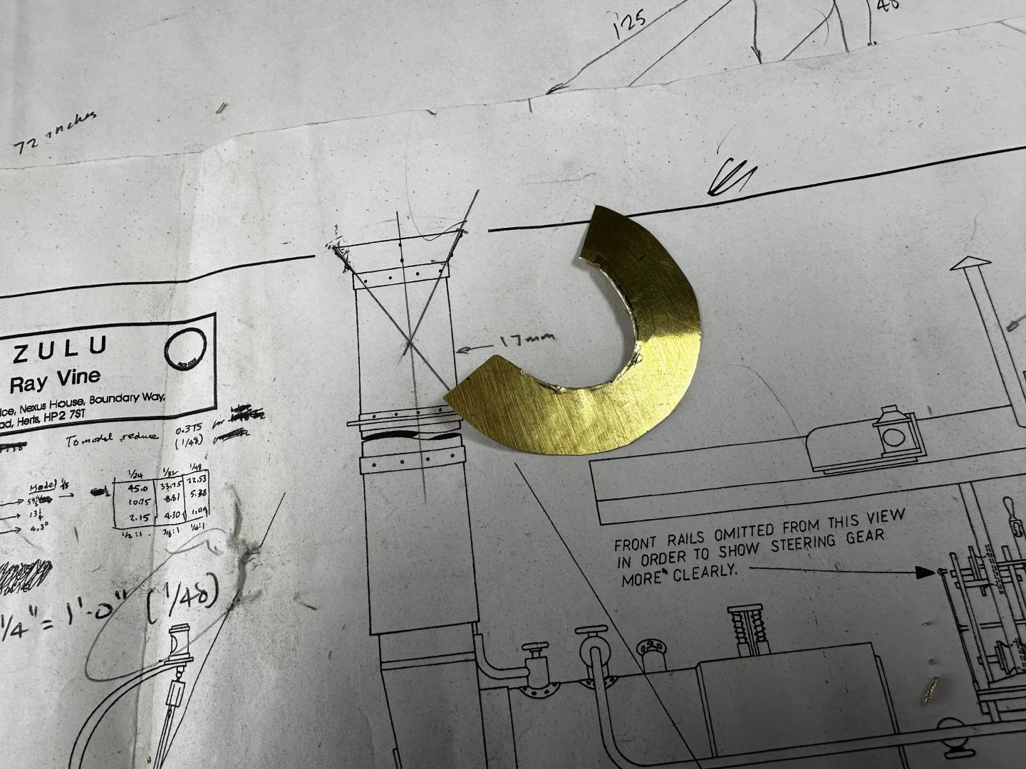
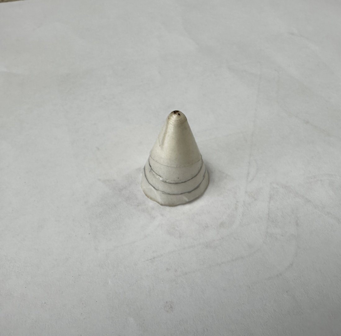
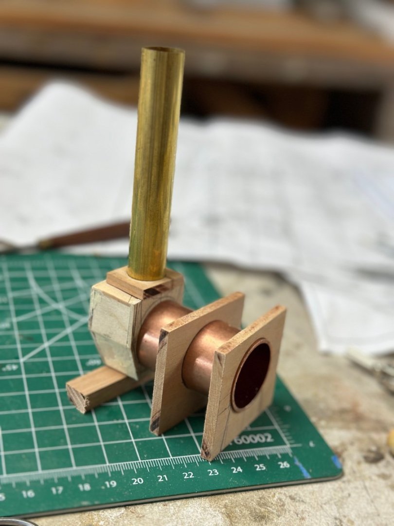
For some time I have been experimenting on how to build the conical top of the stack. At first I tried using the bottom from a dixie cup after strengthening it with shellac ( See Post #37). The results were fair, as the cone was very fragile and I didn't find a good way of trimming the bottom. Today I decided to try my luck with brass. I used thin shim brass plate and developed the cone right on the drawing. Then I cut the plate with scissors, using the Admiral's eyelash curved scissor on the small circle and trimmed the edges with the Dremel.
Bent the plate over a brass rod.
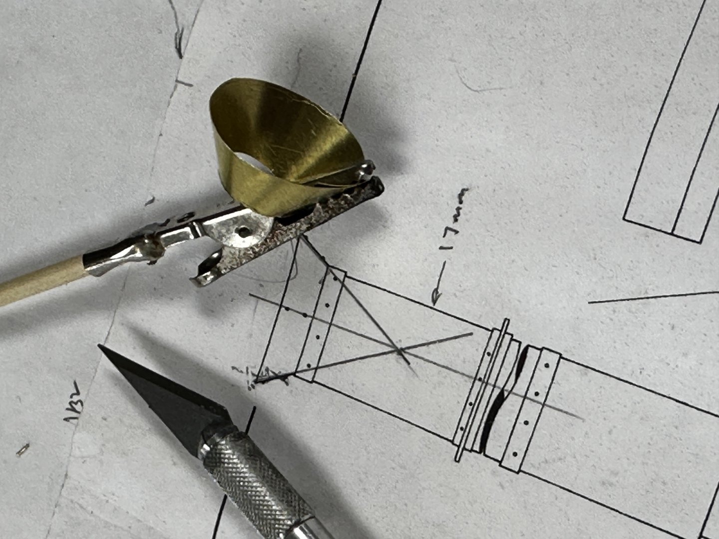
And glued it together using CA. I thought about soldering it "a la Valeriy" but I wasn't to sure about the results. I promise that, when I finish this boat, I am going to practice both of my nemesis: soldering and air brush painting.
And here it is my cone waiting for the glue to cure.

Thanks for all the likes wows.
-
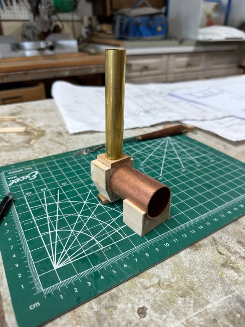
Continuing the work on the pumps. First was the fabrication of the suction manifold for the condensate pump. This was followed by the dry fitting of the condensate system.

My soldering attempts.
 The finally dry fitted on site the suction piping to the condensate tank in the engine room. Need a little more work on the squareness of the pipe elbows.
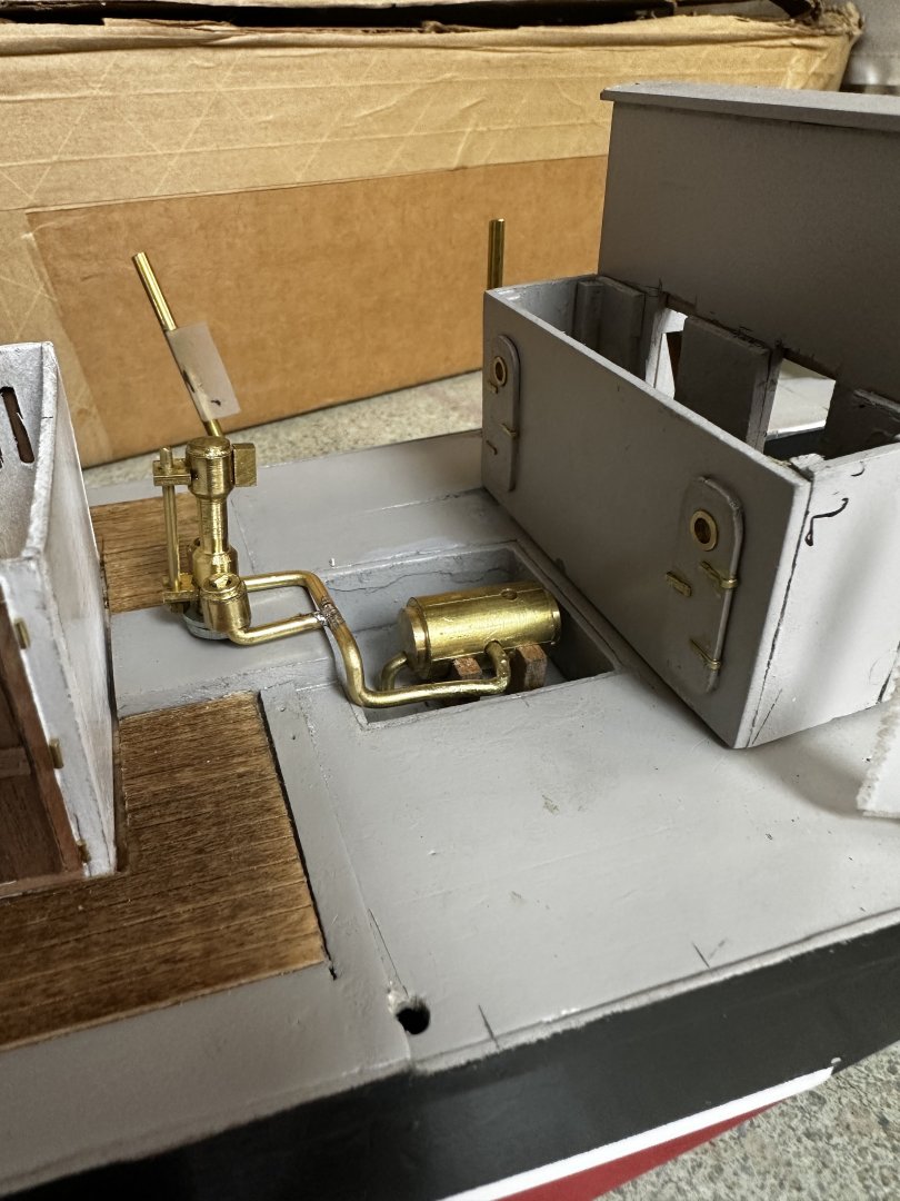
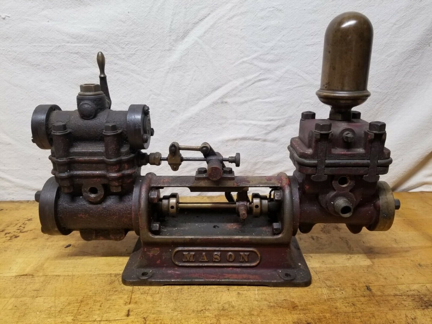
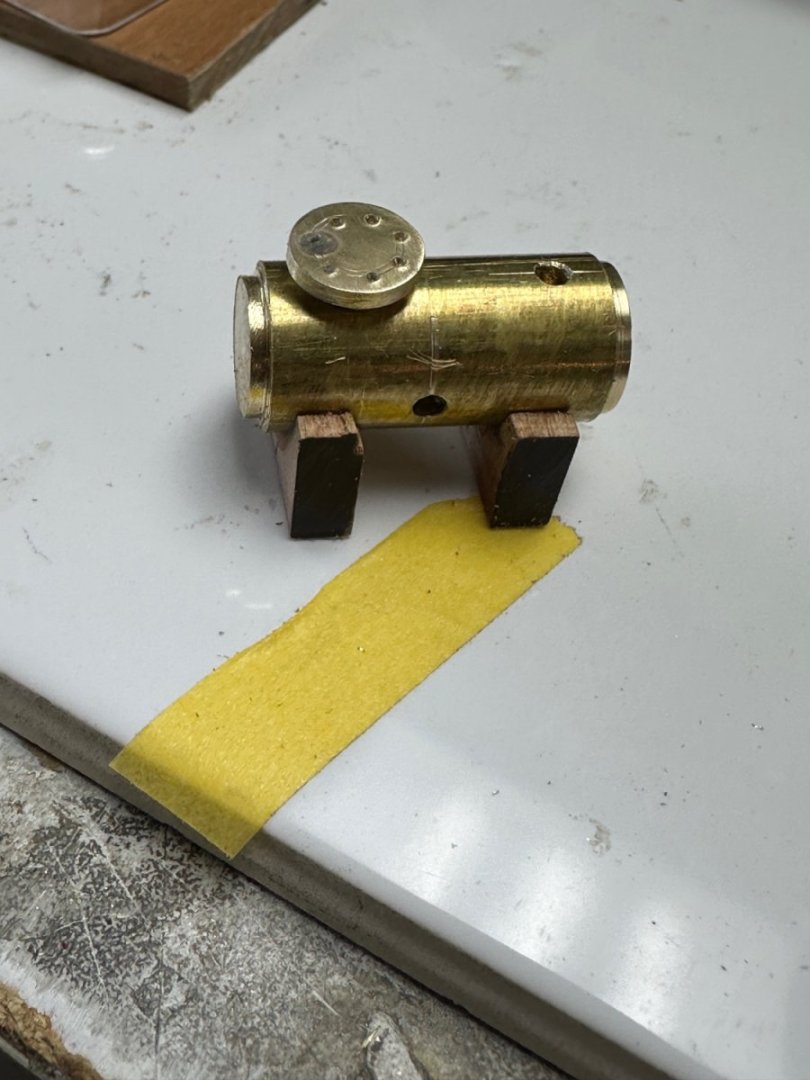
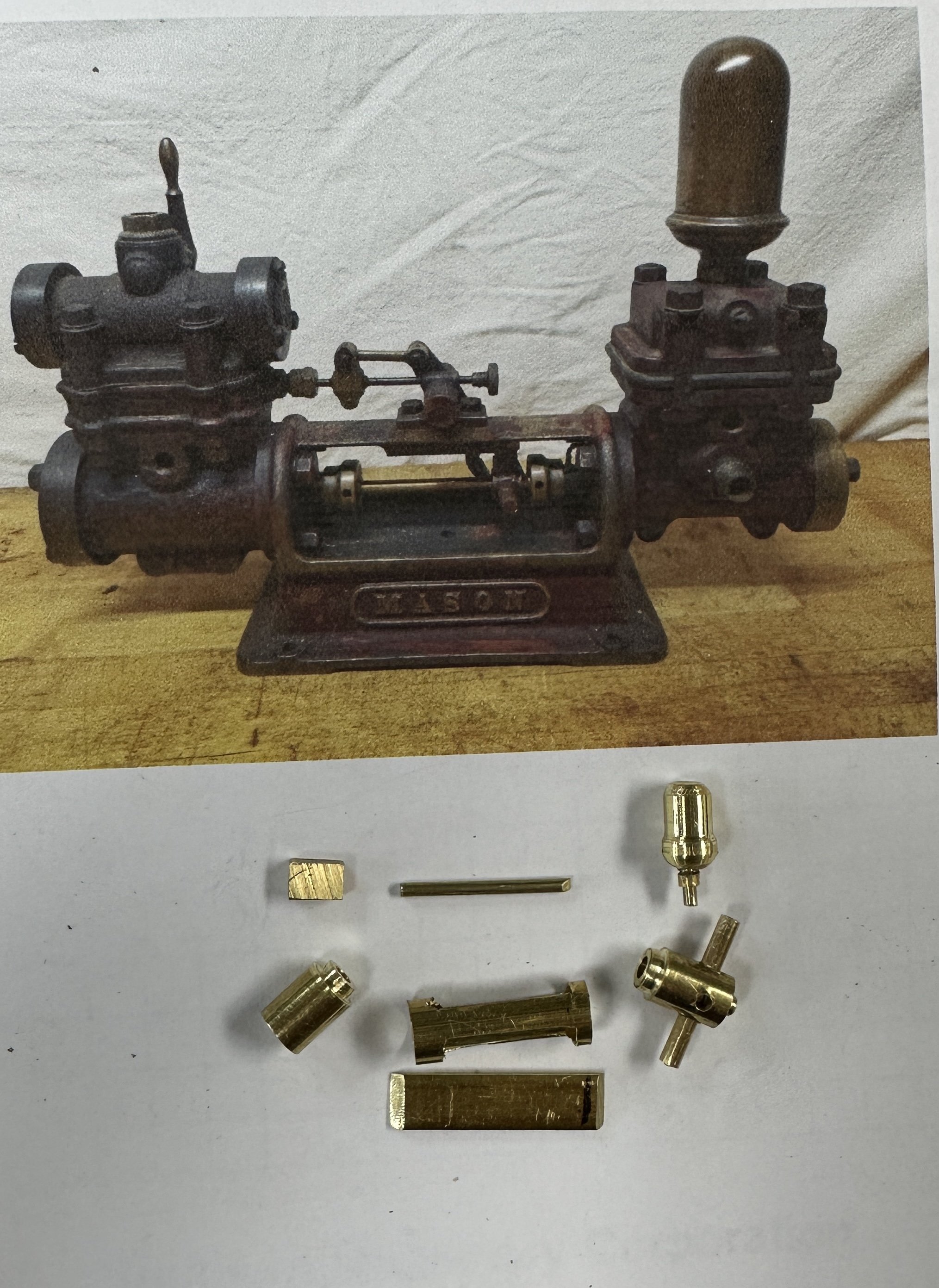
Then the Mason boiler feed pump followed.
I have to say I love working the lathe. I am not as good as I used to be in my younger years but it is a pleasure to see the cuttings fall.
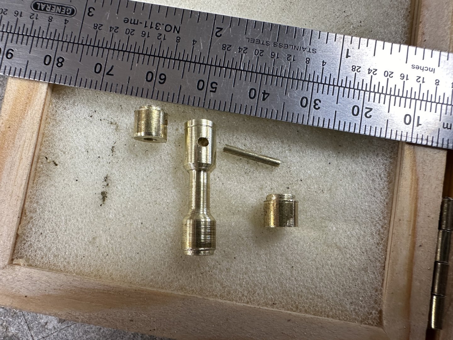
This are some of the parts.
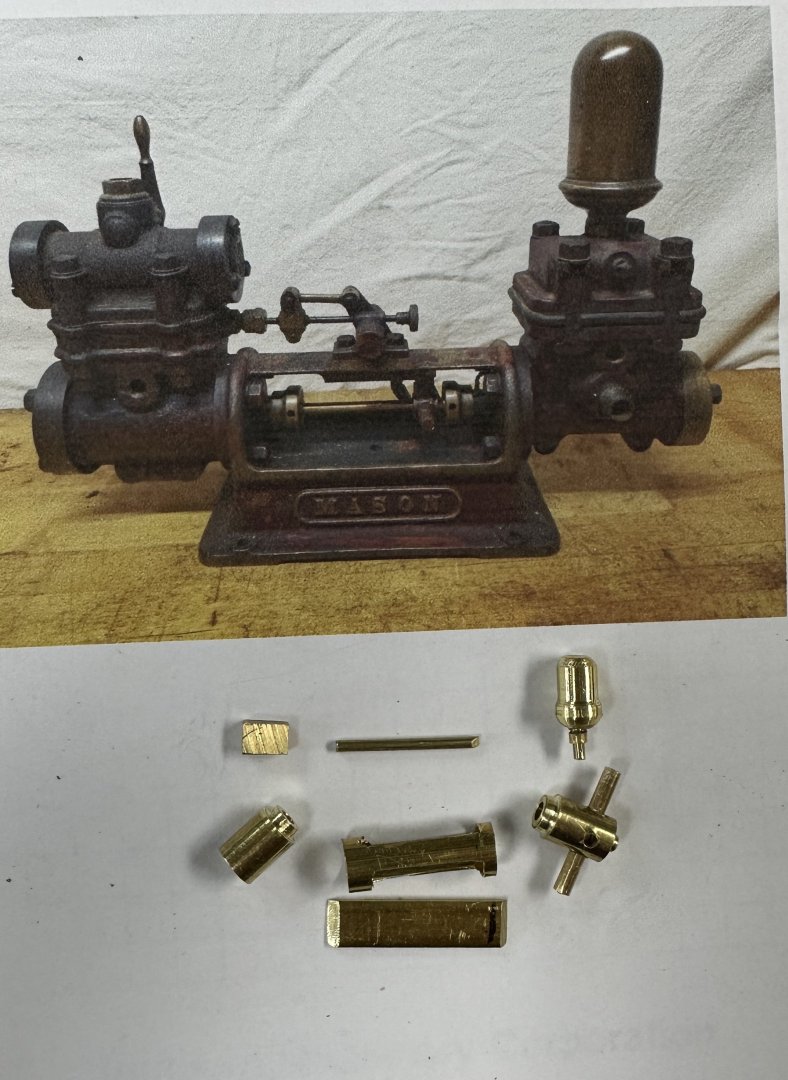
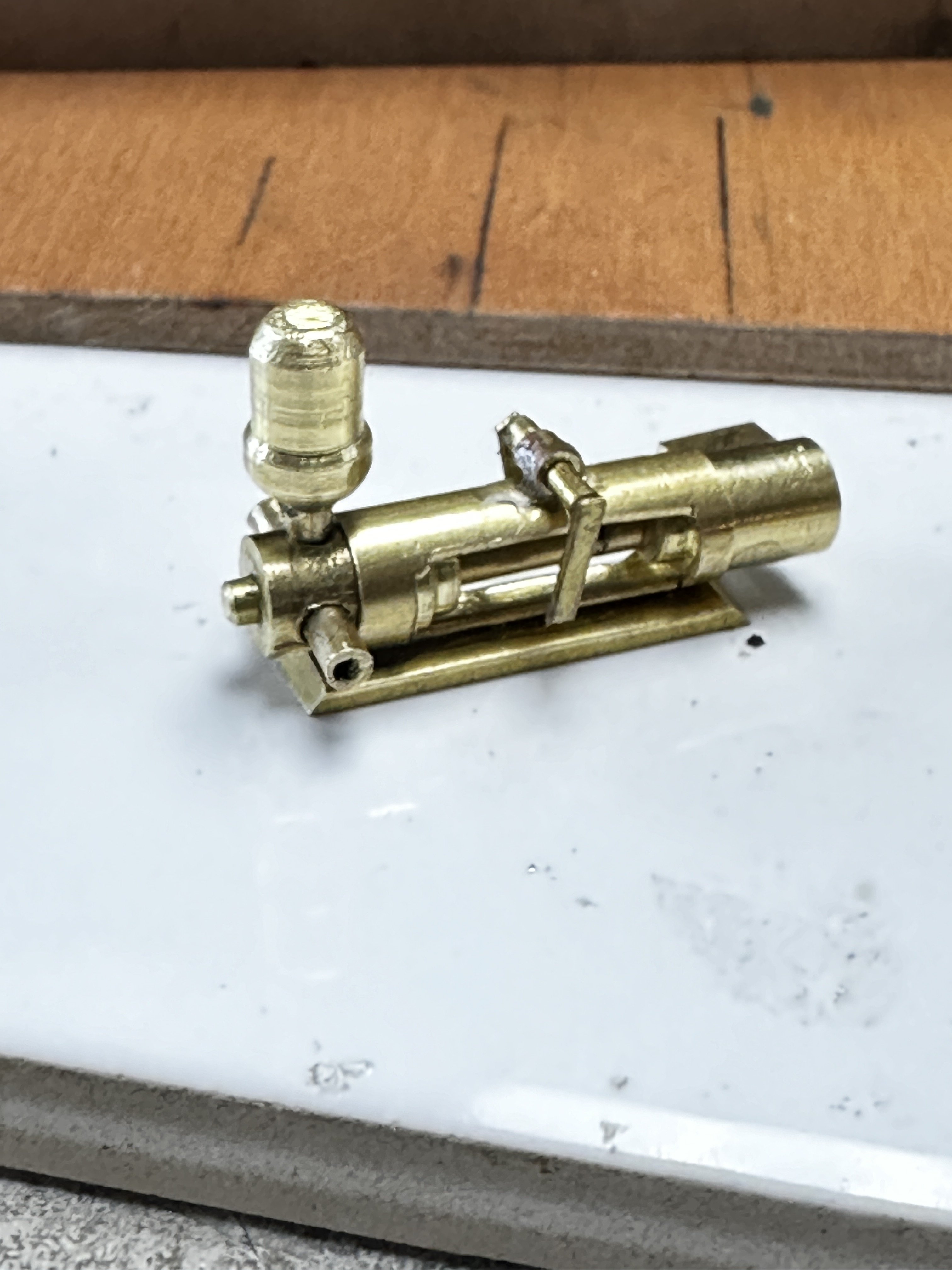
Then the dry fit assembly
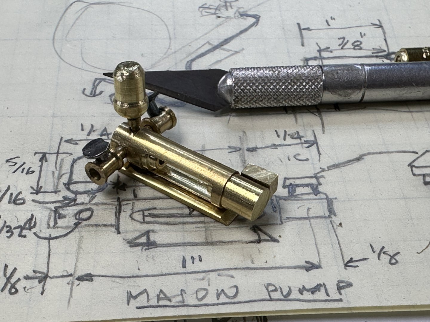
And the final product.

Thanks for following
-
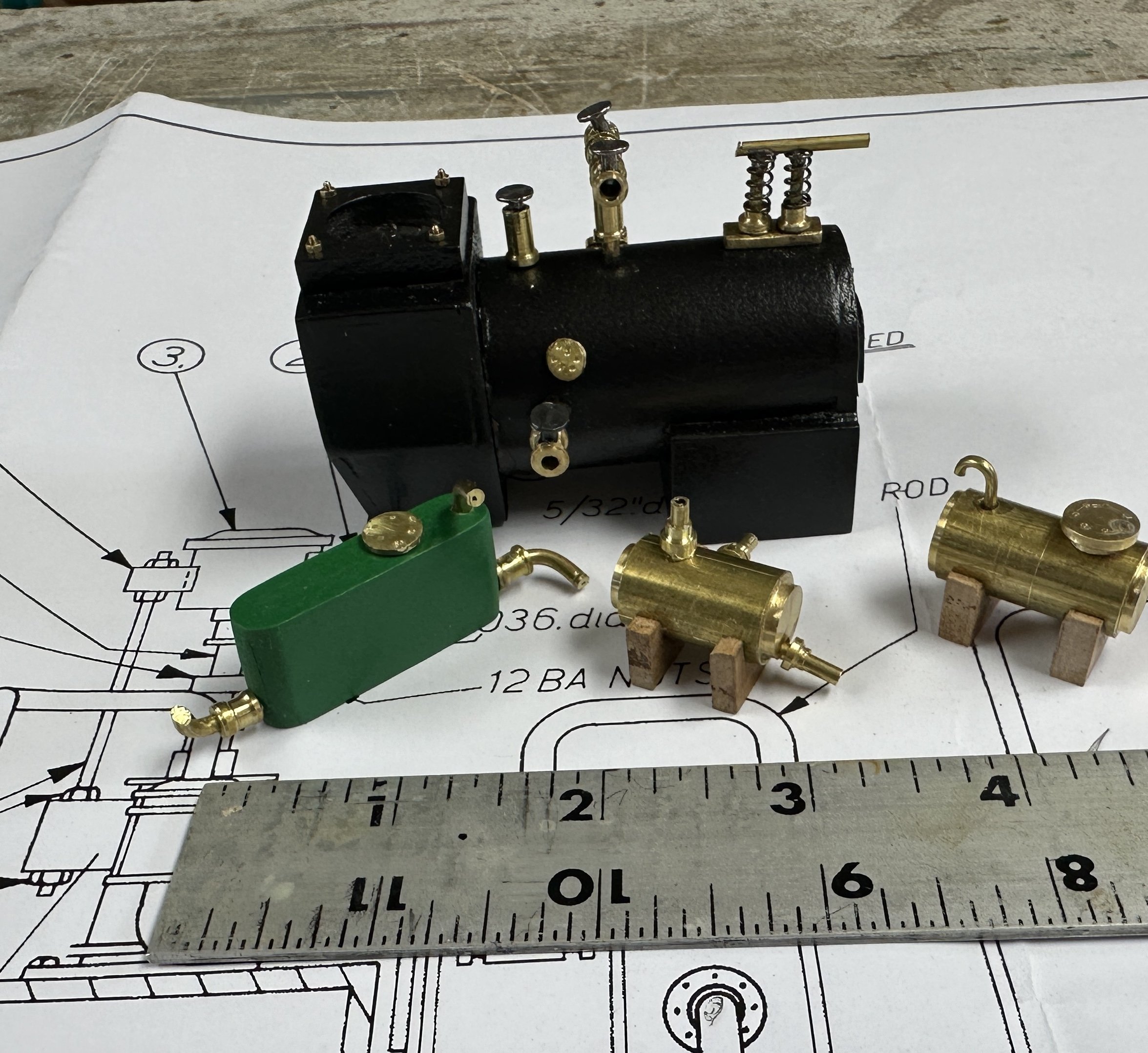
The boiler and water tanks.
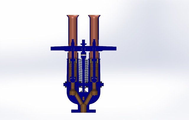
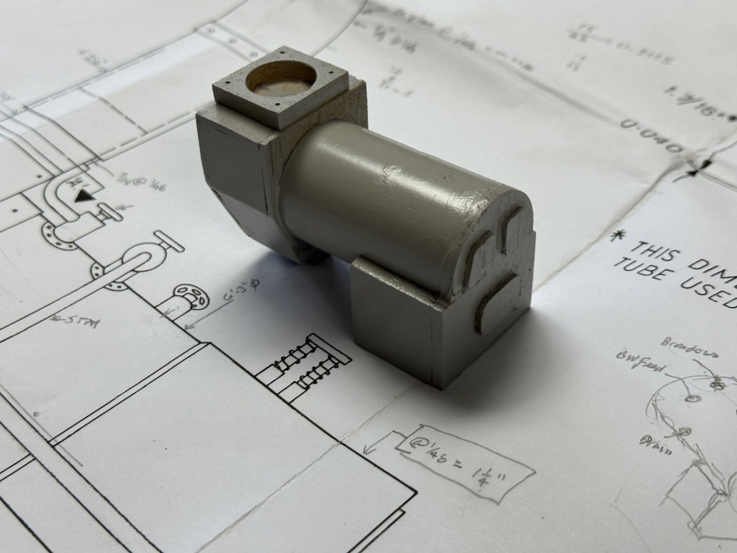
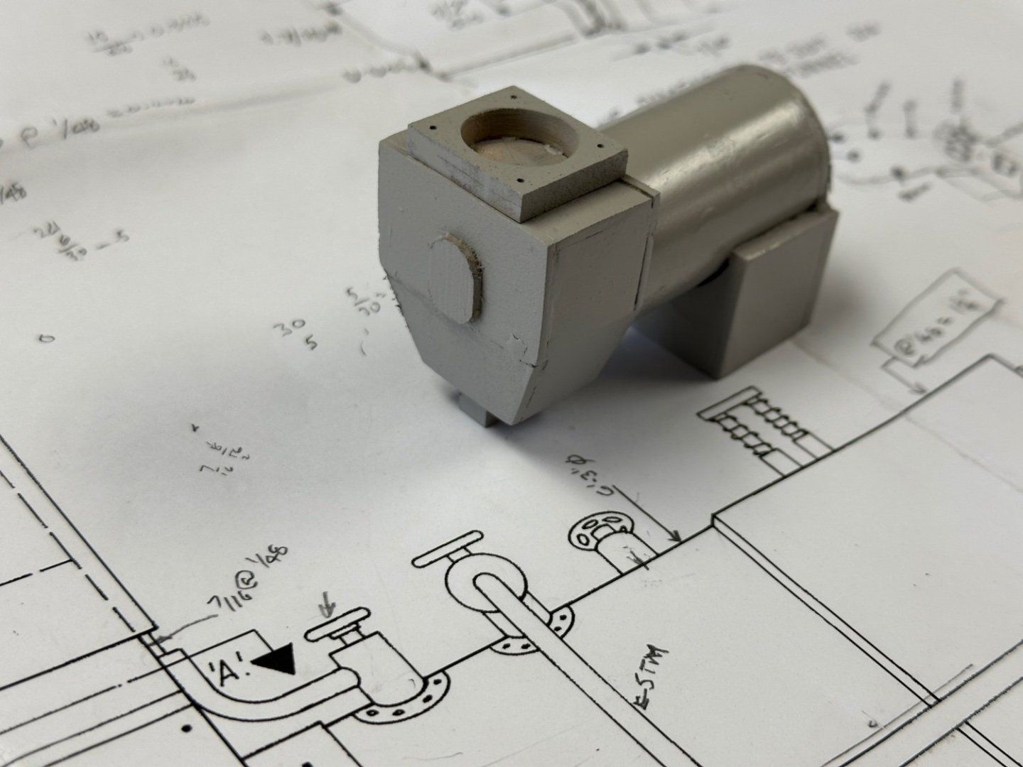
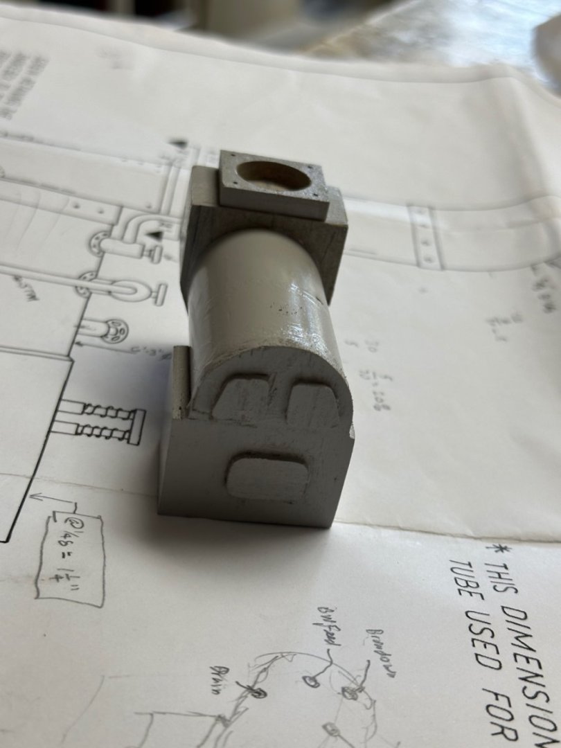
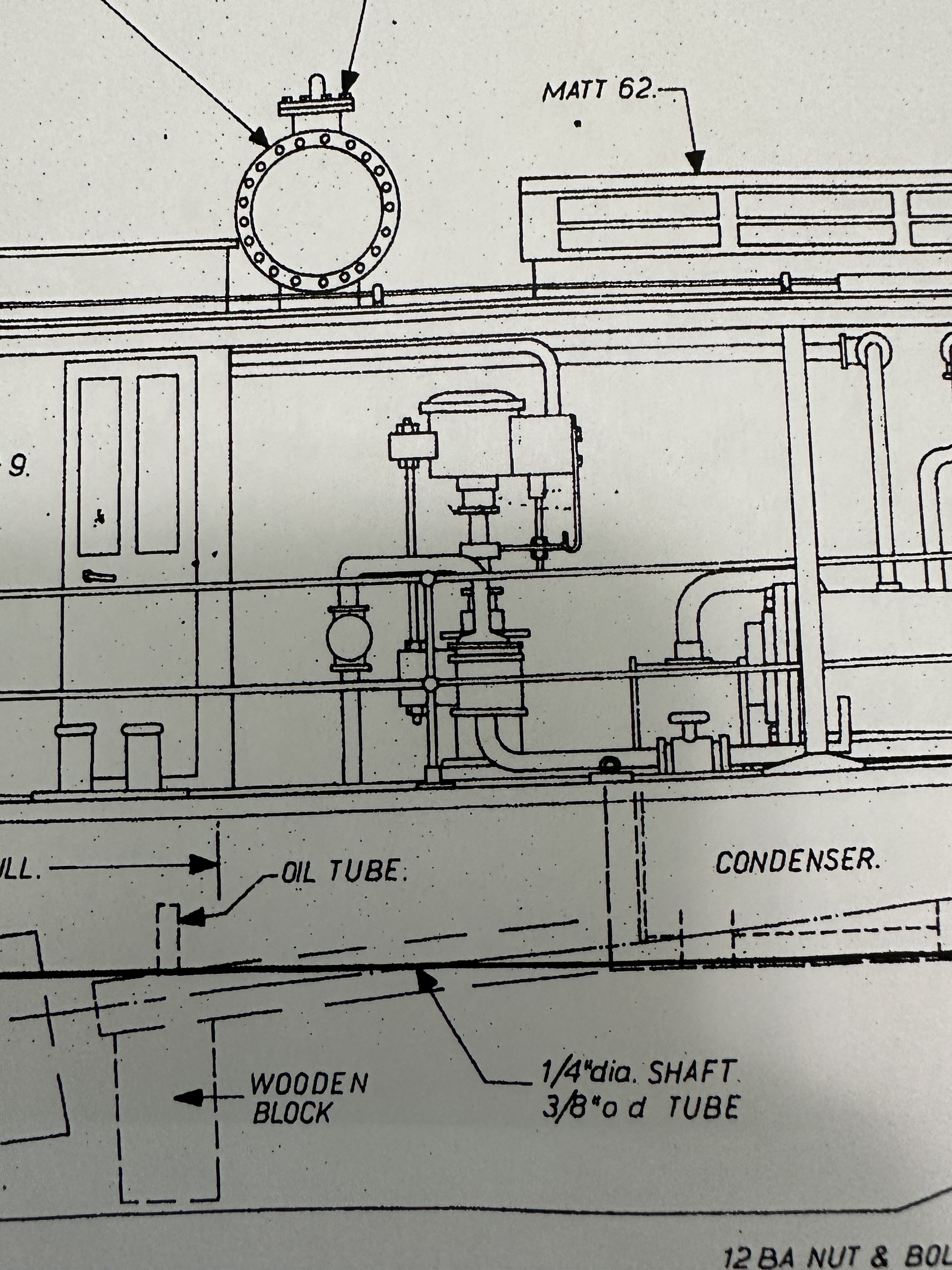
 The vertical condensate return pump under construction. First the plans.

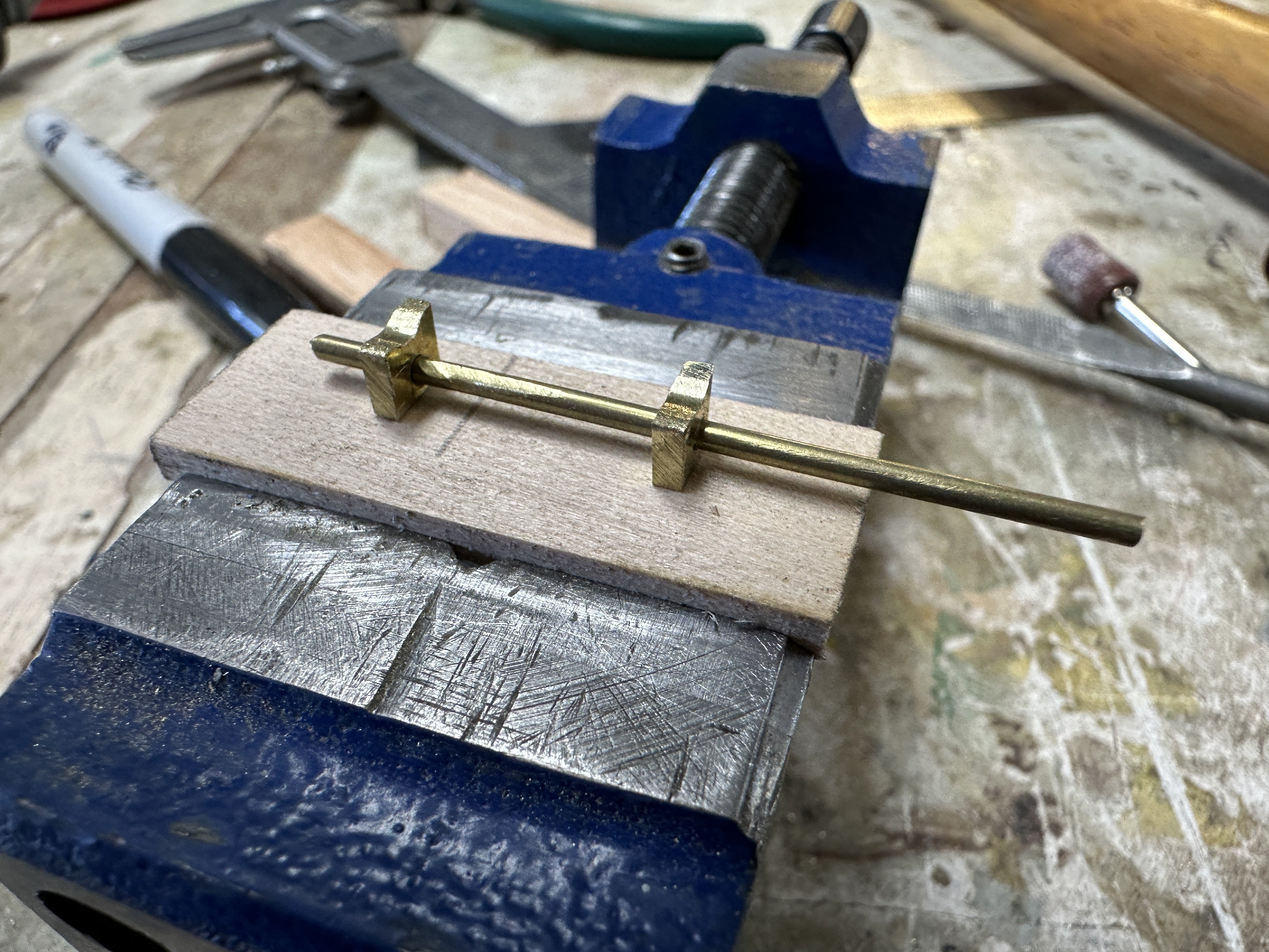
The construction in process.


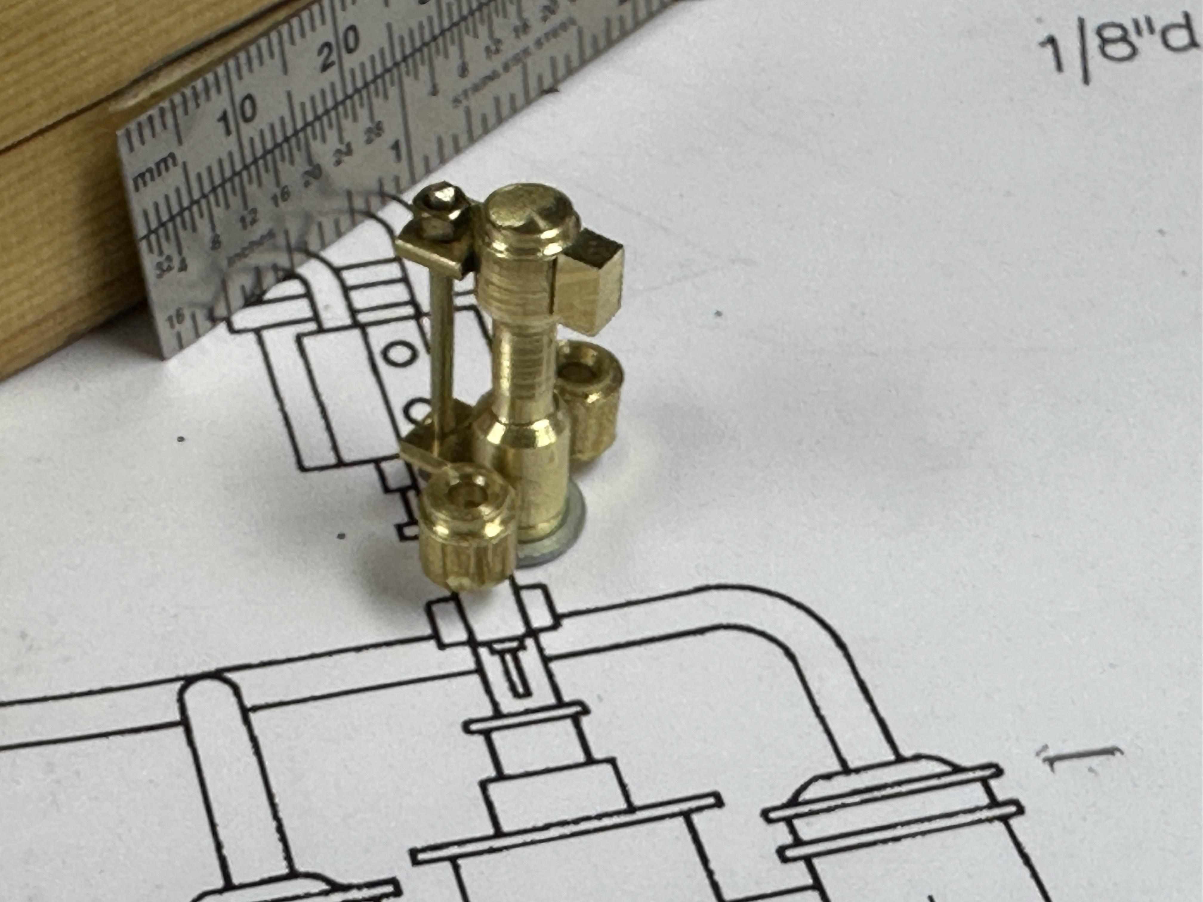
And the finished product

My 0.5 mm tolerances were challenged in this project. After this I will tackle the boiler feed pump which is a horizontal
design.
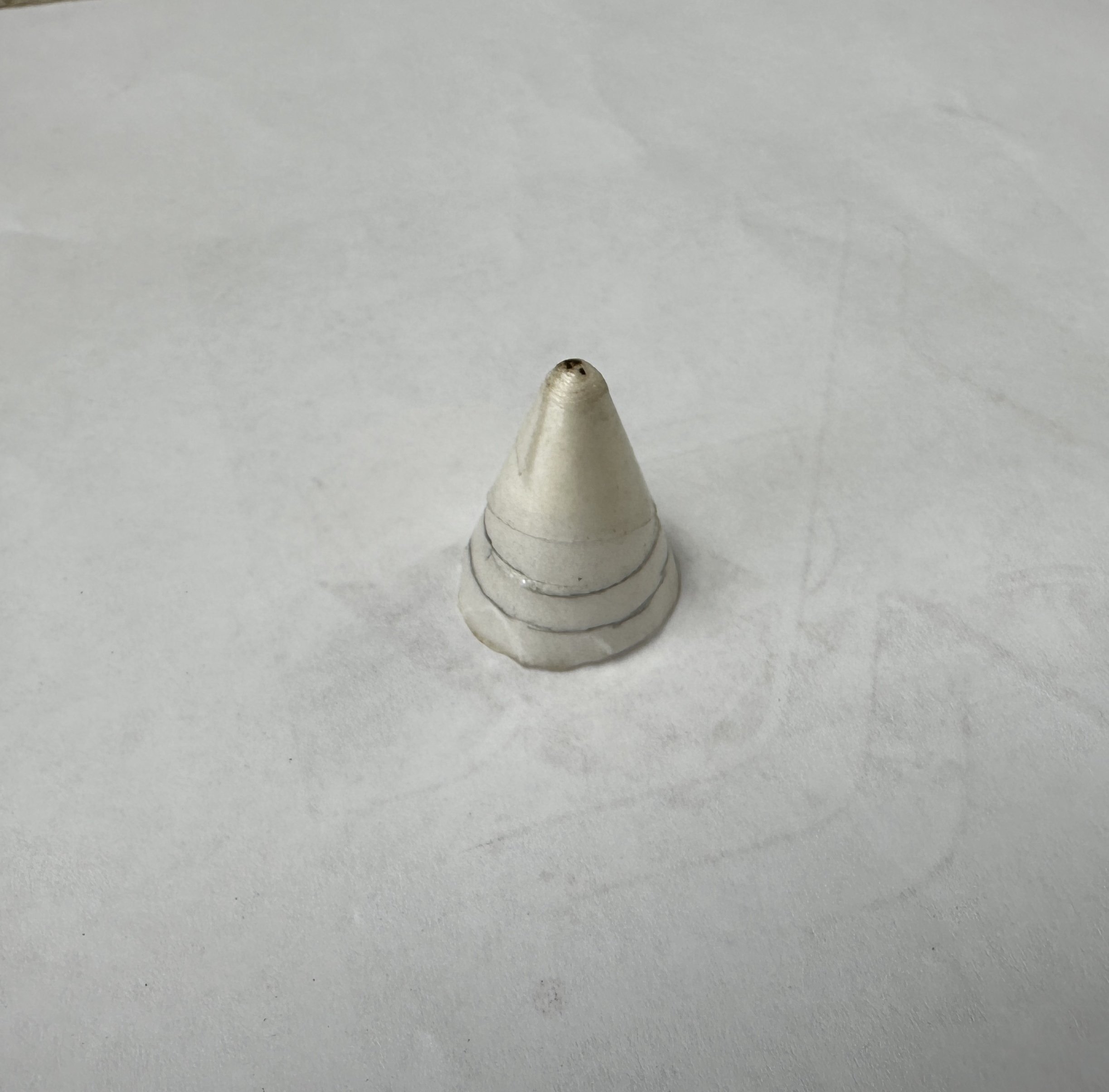
And finally the results of my experiments for boiler stack conical top. I used the bottom of a cone water drinking cup that was stiffened with several layers of lacker following Wefalk experience.
Going to try again by developing the cone in thicker card a perhaps even brass plate. We will see what happens.
Having fun, and thanking y'all for the likes and comments.
-
The Admiral is back and I am back to a slow move in the build. I have been working on the stack figuring out to provide a conical champher on the stack top. Right now I am trying Wefalks use of lacquered card. In the meantime I started the water tanks. Following in the results for the fresh water tank.
Thanks a lot for the likes. You are my support and inspiration.
-
-
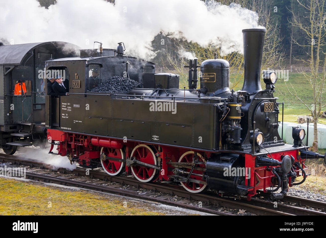
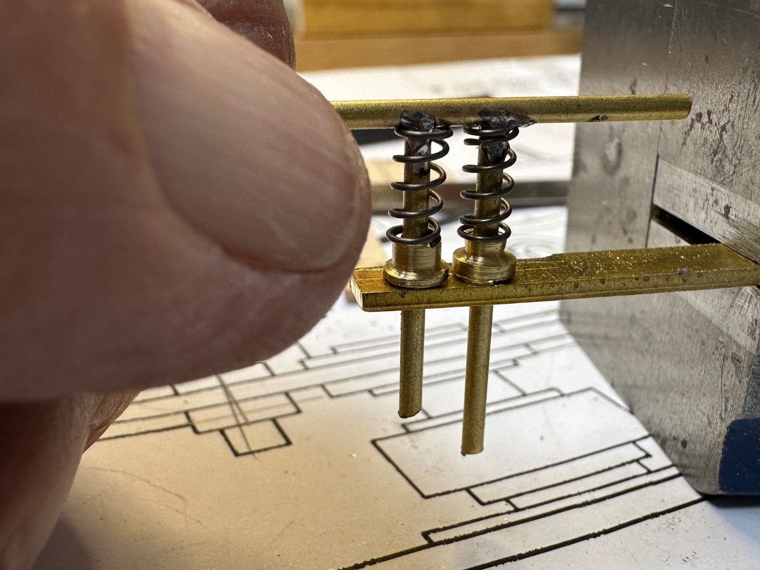
Wefalk, I thought so too but, when I looked at the results on google some of these valves were discharging in the open. The drawings I have show a separate vent for the boiler itself. Also in my research the externally sprung valves had an extension in the connecting bar on the top of the springs. My guess is that it is a handle for manual release. Any way this arrangement was easier to make than some of the ones I saw in my research. Like the one below.
This one is called a Ramsbottom safety valve. Used in the Württembergische T3 locomotive.
- GrandpaPhil, Canute, mtaylor and 2 others
-
 5
5
-
I agree with Wefalk, this is our hobby and we really have no deadlines.
- Keith Black, FriedClams and mtaylor
-
3
-
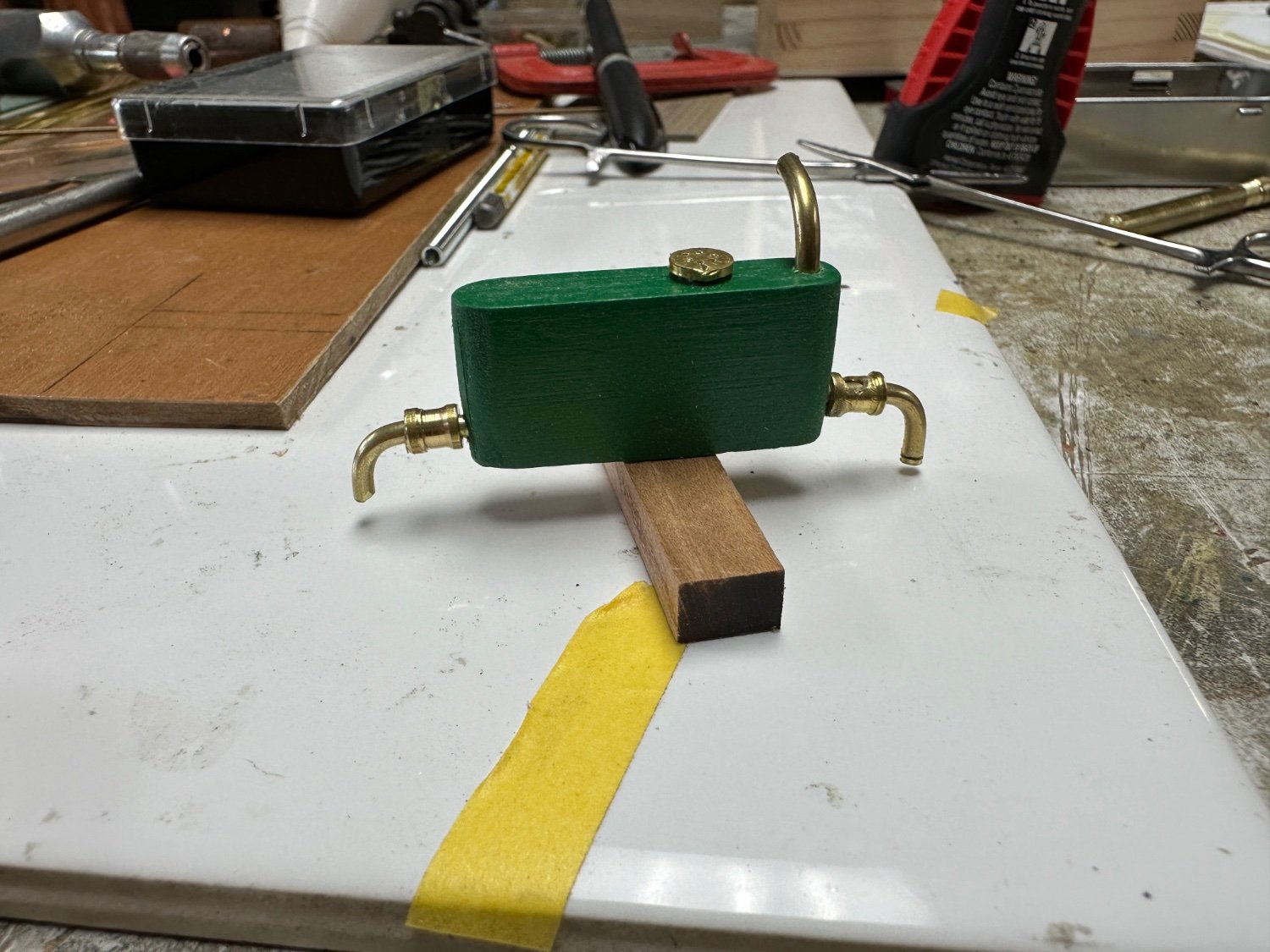
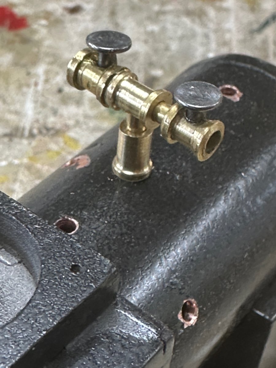
Still working on the boiler. The current challenge is the boiler piping. Yesterday the steam supply manifold was completed.
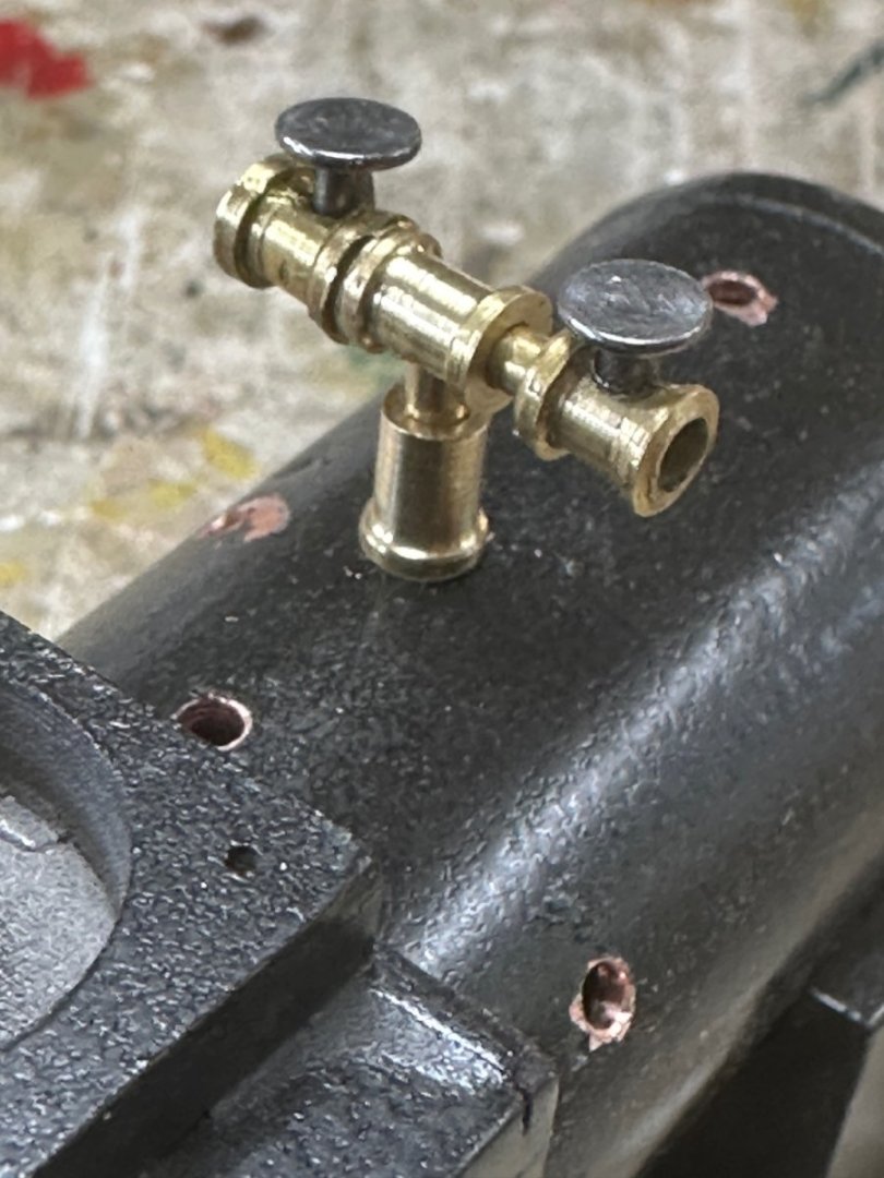
Today the challenge was the steam pressure relief valve. I researched it but couldn't agree with any of the options. So, I decided to reproduce the one shown in the plans.
And this is the results:
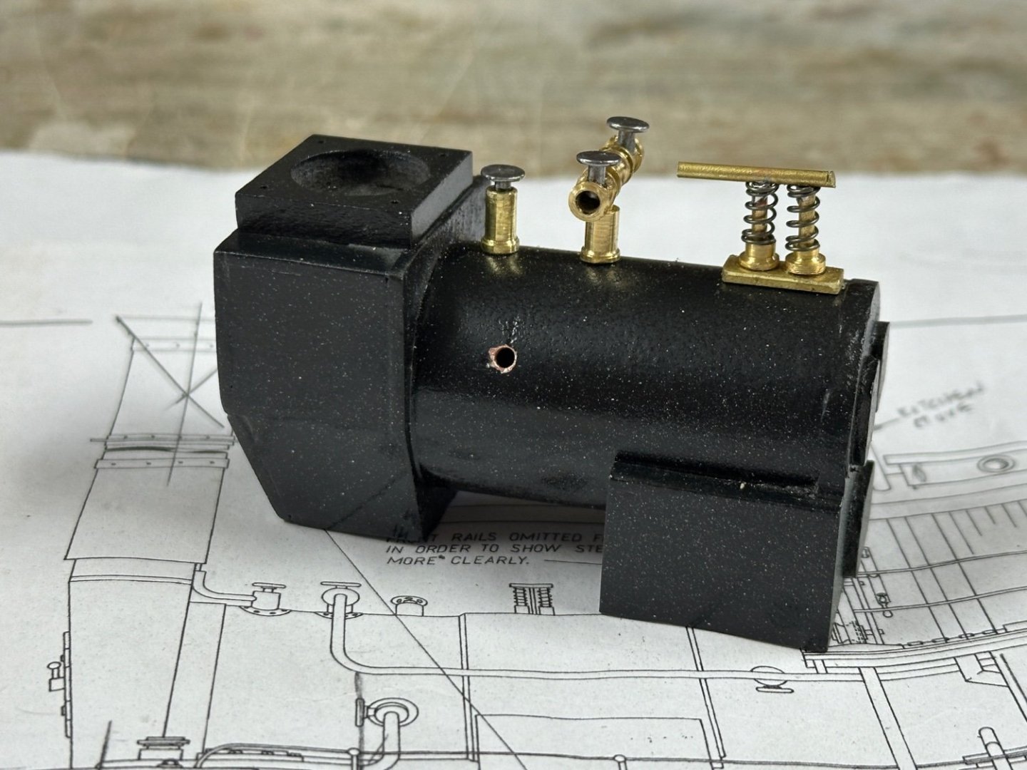
The valve on the left is for the steam vent that will routed by the stack.
Thanks for following.
-
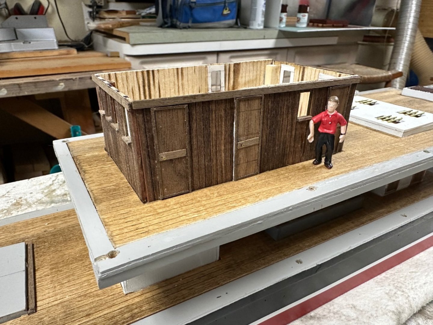
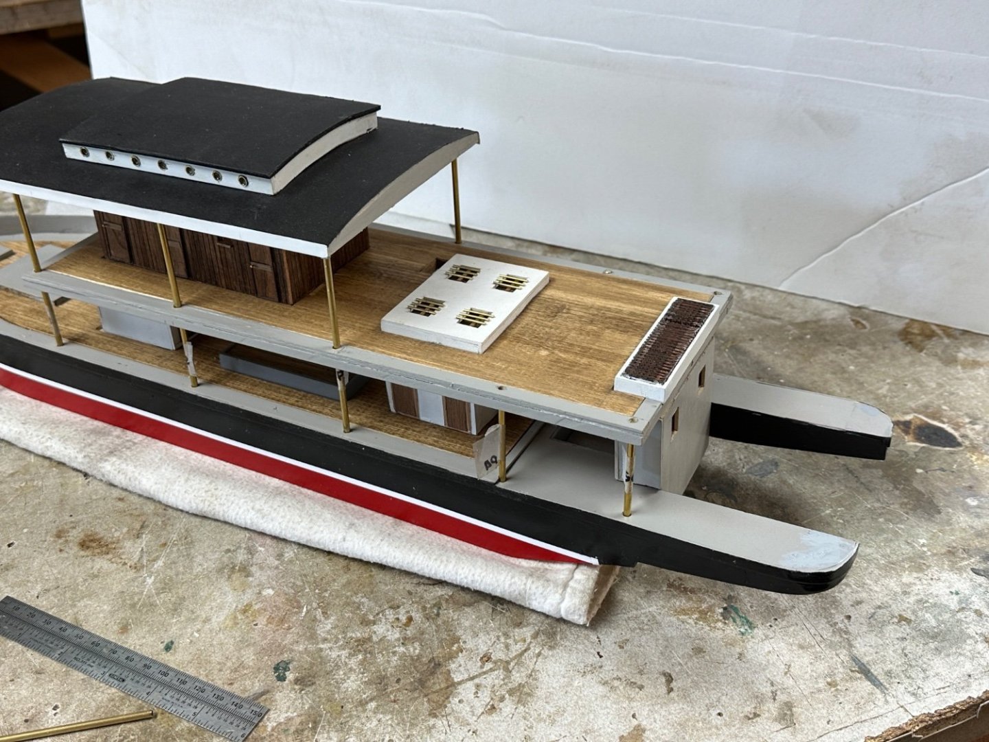
A little more progress. Currently finishing the mechanical room aft. A few shots with the roof removed. It is amazing how much detail, that we for so long labored, gets lost once the model is put together.
Again the black paint kills details in the boiler.
And the first passenger is checking out his cabin.
-
-
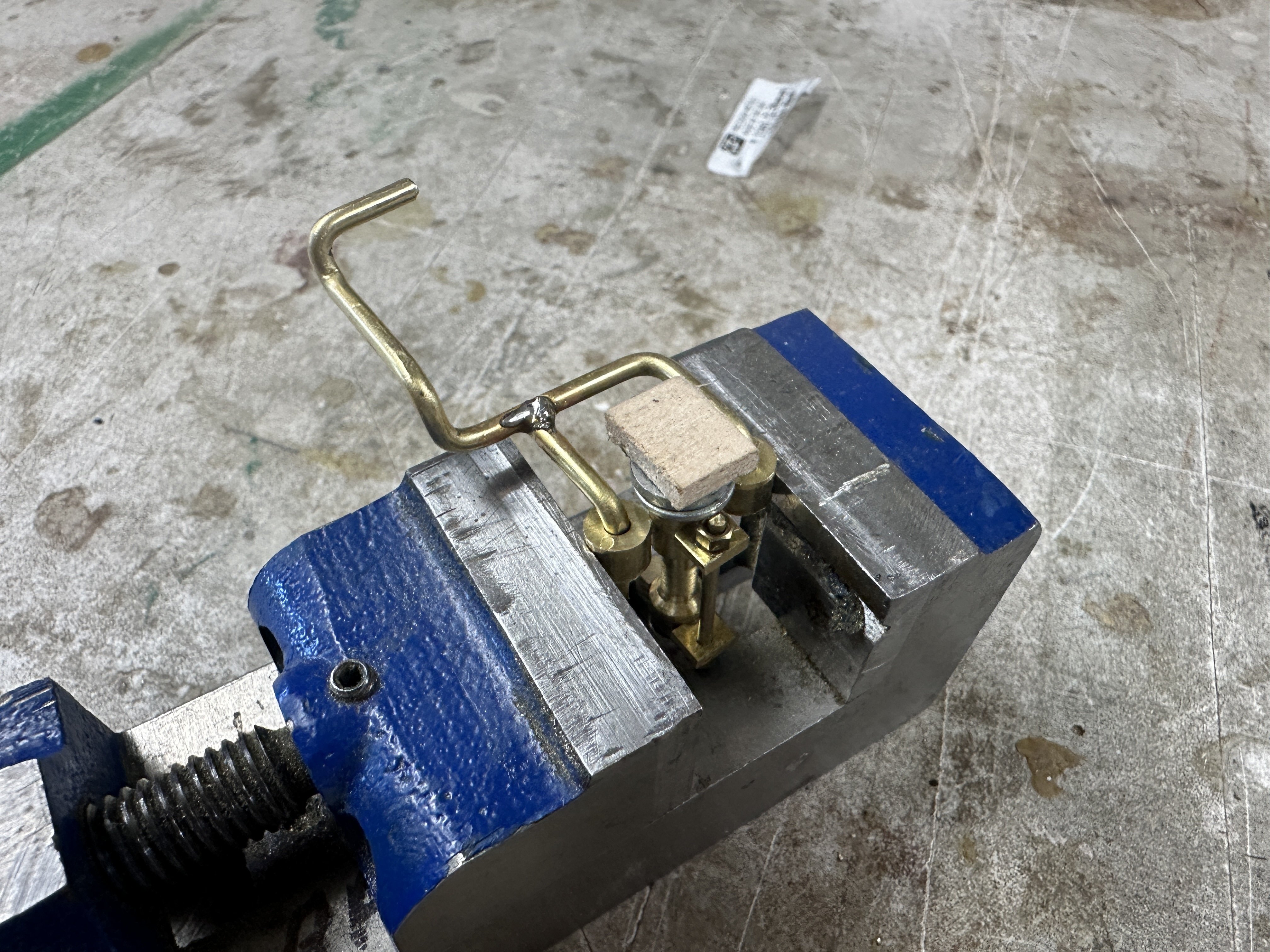
Being a little lazy lately. The Admiral has kept me busy elsewhere. But, I still had some time to test my micro soldering. Still not very happy with the results but at least I found a good technique to use. Following are the photos of my set up and the result on micro door handle.

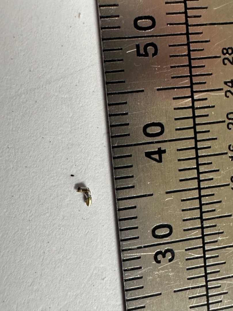
Also, some progress on the boiler.
Hinges and latches come next. Wife gone on a safari in Borneo. That will give me a little more time to play. LOL
- KeithAug, Roger Pellett, mtaylor and 5 others
-
8
-
Wefalk, you don't cease to amaze me.👍
- Keith Black, FriedClams, mbp521 and 1 other
-
4
-
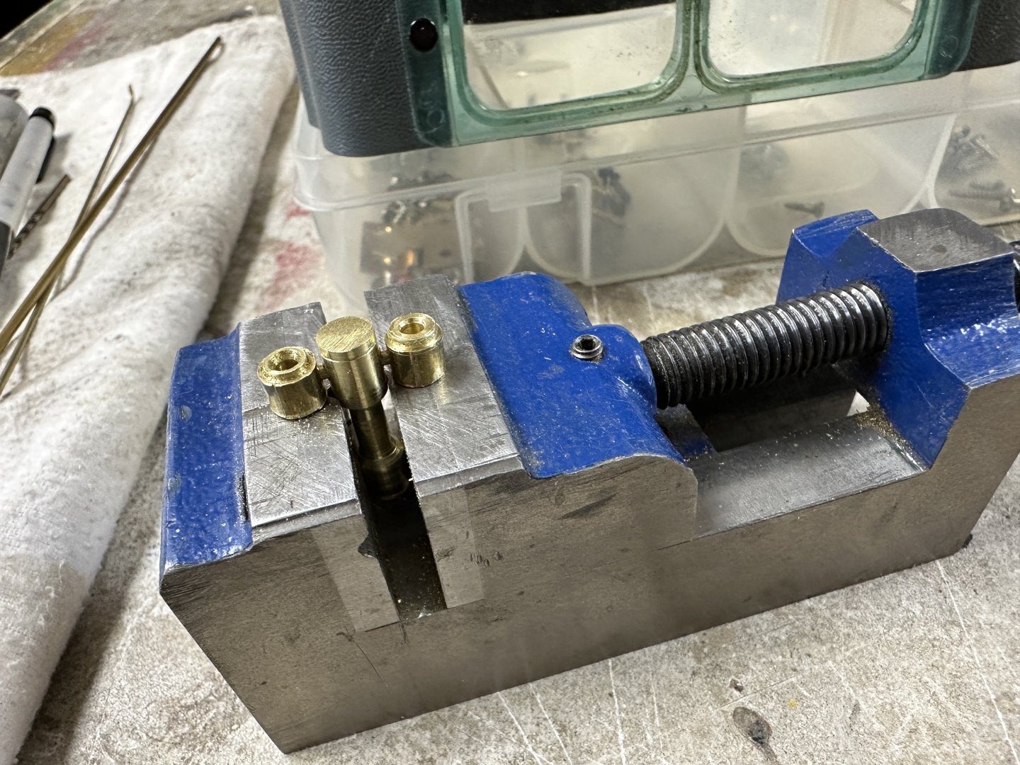
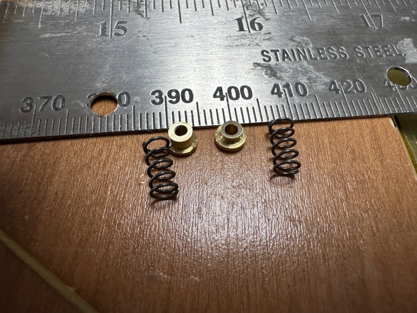
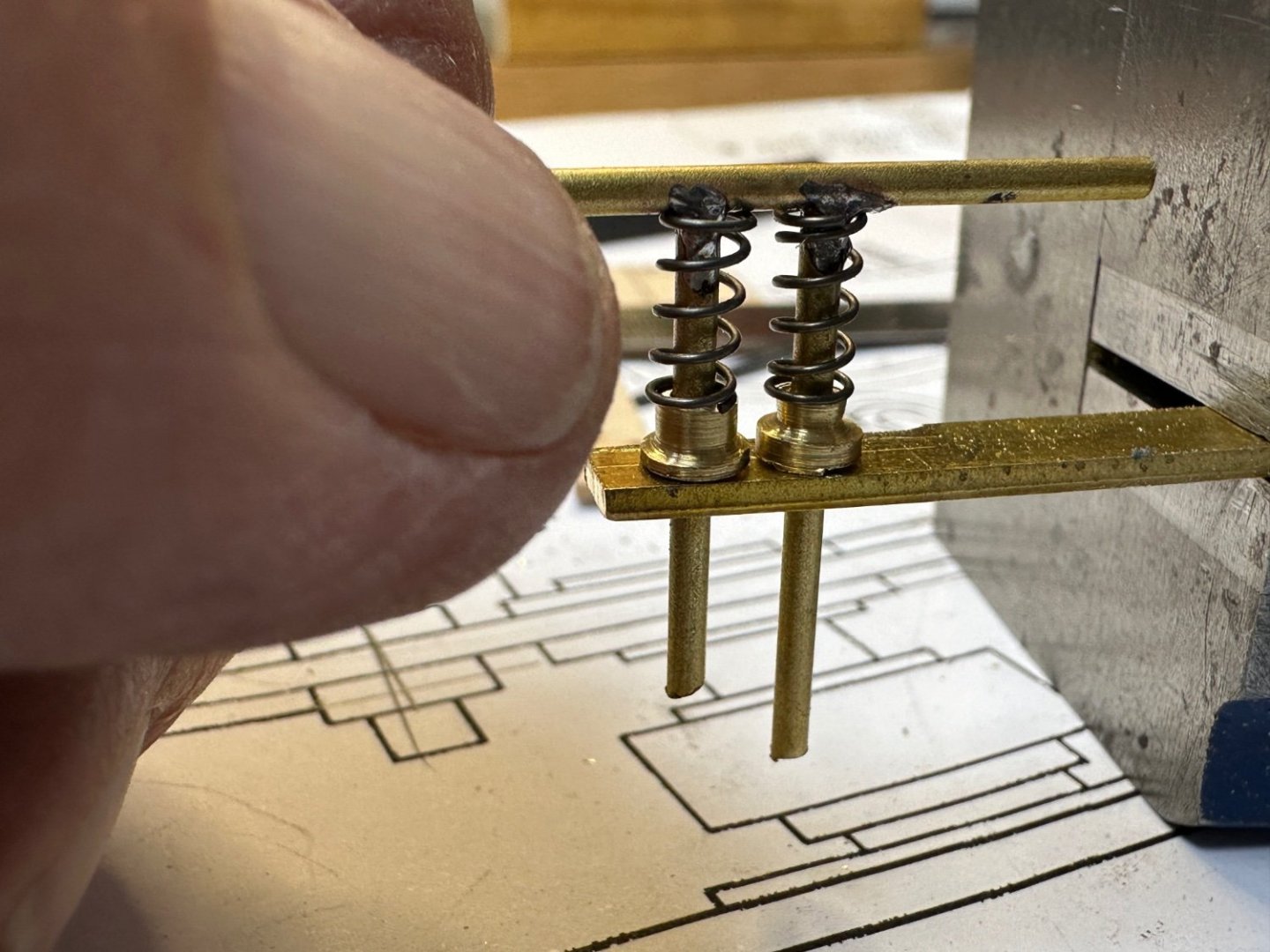
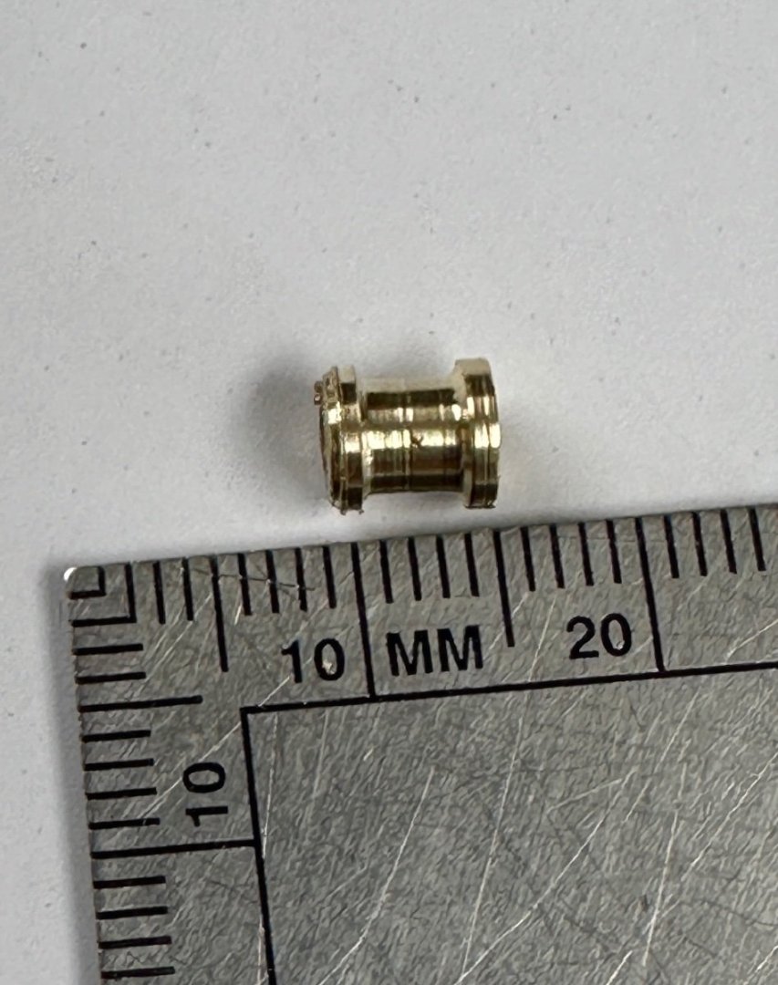
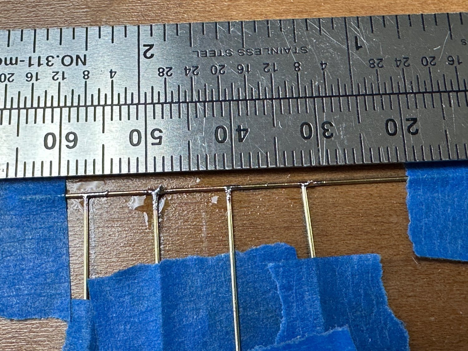
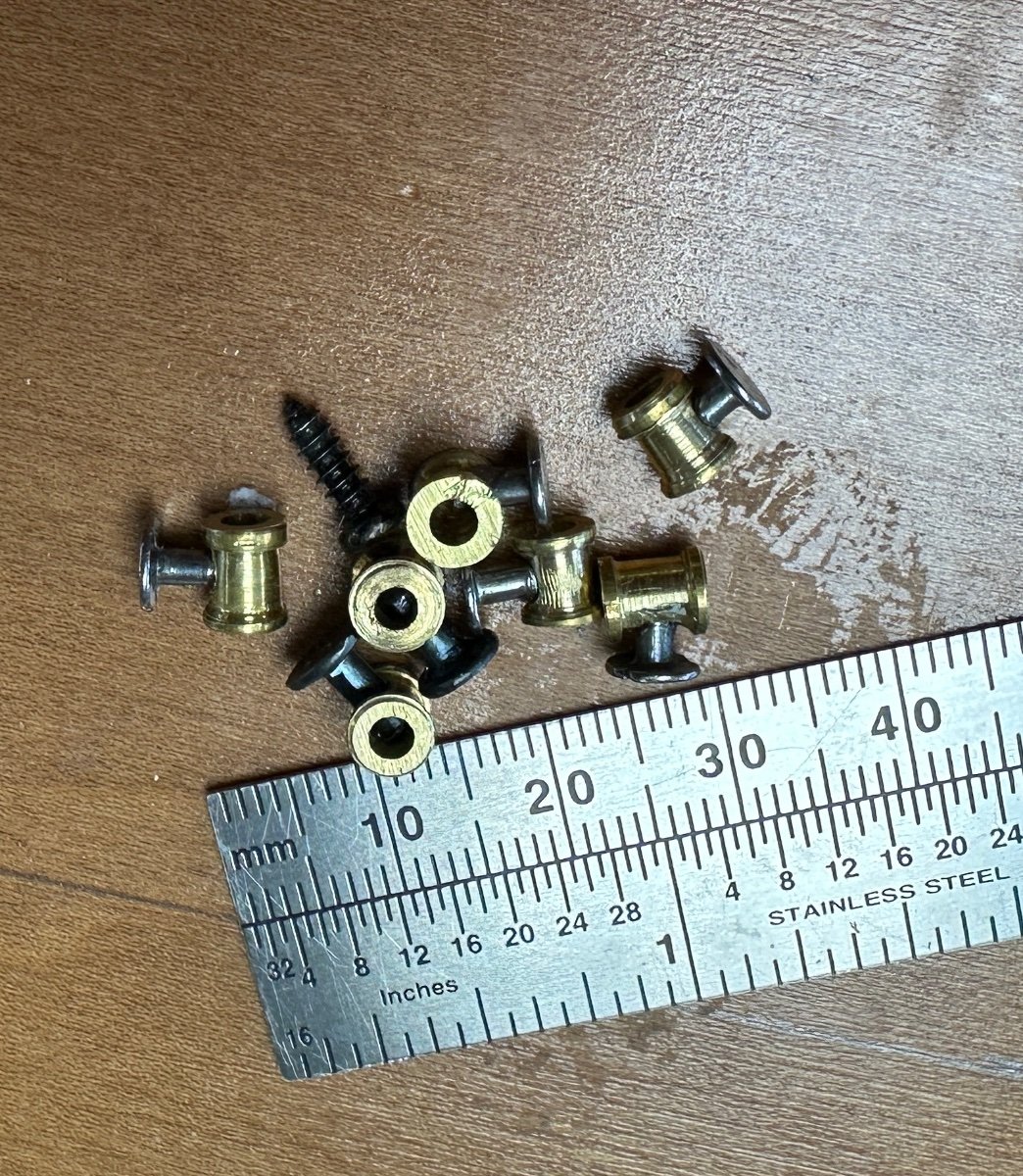
I have been working on the valves with some success and finally fabricated an acceptable mini valve. Started with a much larger rod then ordered the right size (3/16") but had difficulty with the cutters in the lathe. Decided to fabricate the valves in a mass production cutting each valve in series so I would cut the body leaving the thickness of the flange and the cut another body etc. The result was a with a series of flange-body-flange-body-flange........... Unfortunately I didn't take a picture. When I finished the series I took it off the lathe and went to cut each valve apart. Guess what, the distance between bodies was only one flange thickness. I had forgotten to make the series as "flange-space flange-body- flange-space.....". So I started again and this time I did it correctly.
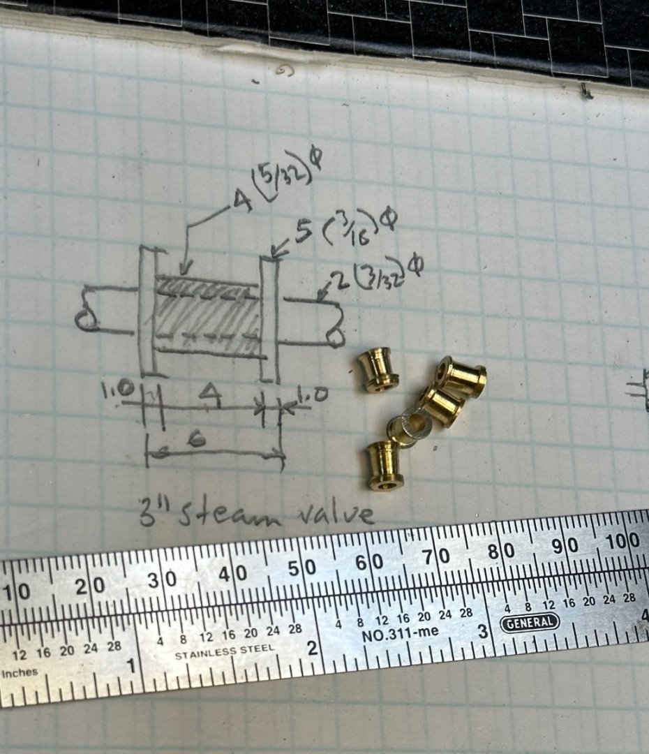
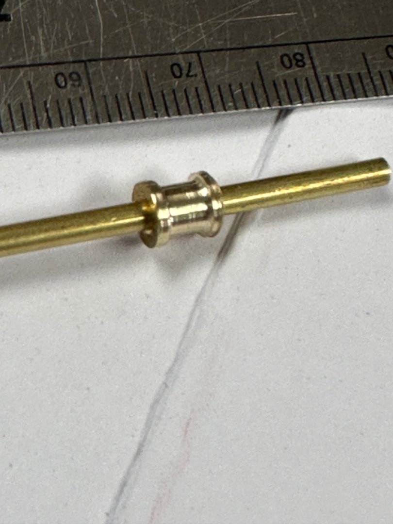
I used tacks for the stem and handle and this how the unpainted valves look.

Thanks for following.
-
Wefalk, you never cease to amaze me with your micro work. Thanks for being such an example to us plebes.
- davec, Keith Black, mtaylor and 1 other
-
4
-
Thanks Glen and Keith for your comments. The lathe is a Unimat. It is an old model but works like a charm even though is not totally watchmakers accurate. It also converts into a mini milling machine.
To the rest of the guys thanks for the likes🙂- mtaylor and Glen McGuire
-
2
-
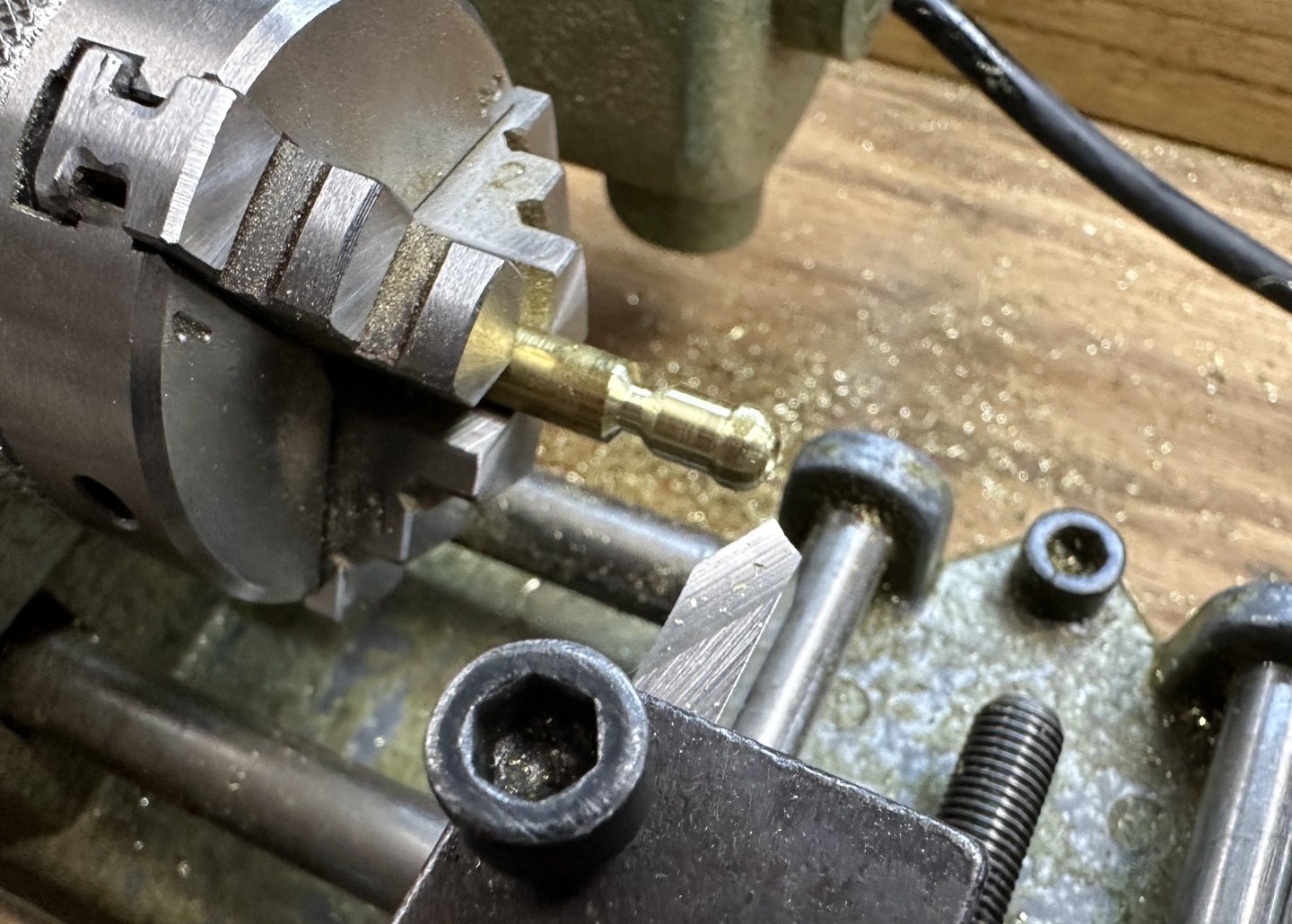
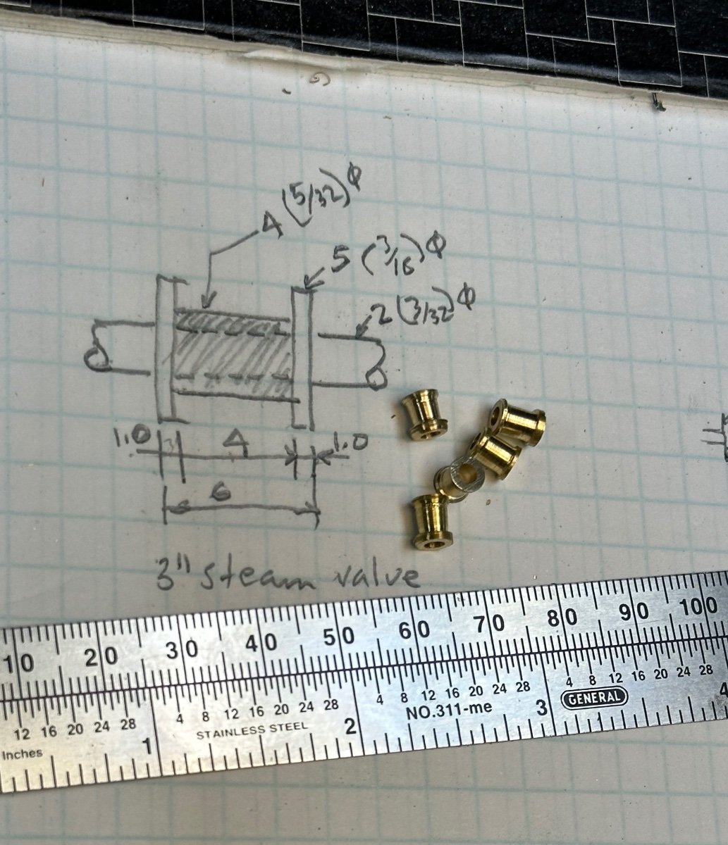
I was itching to start work with the lathe and, I was also figuring out the piping of the boiler/engine system. Right at the start I noticed the large number of valves that would be required. I counted a minimum of 15. So, I am going to bring up the lathe and start making these tiny valves. The fun starts now.


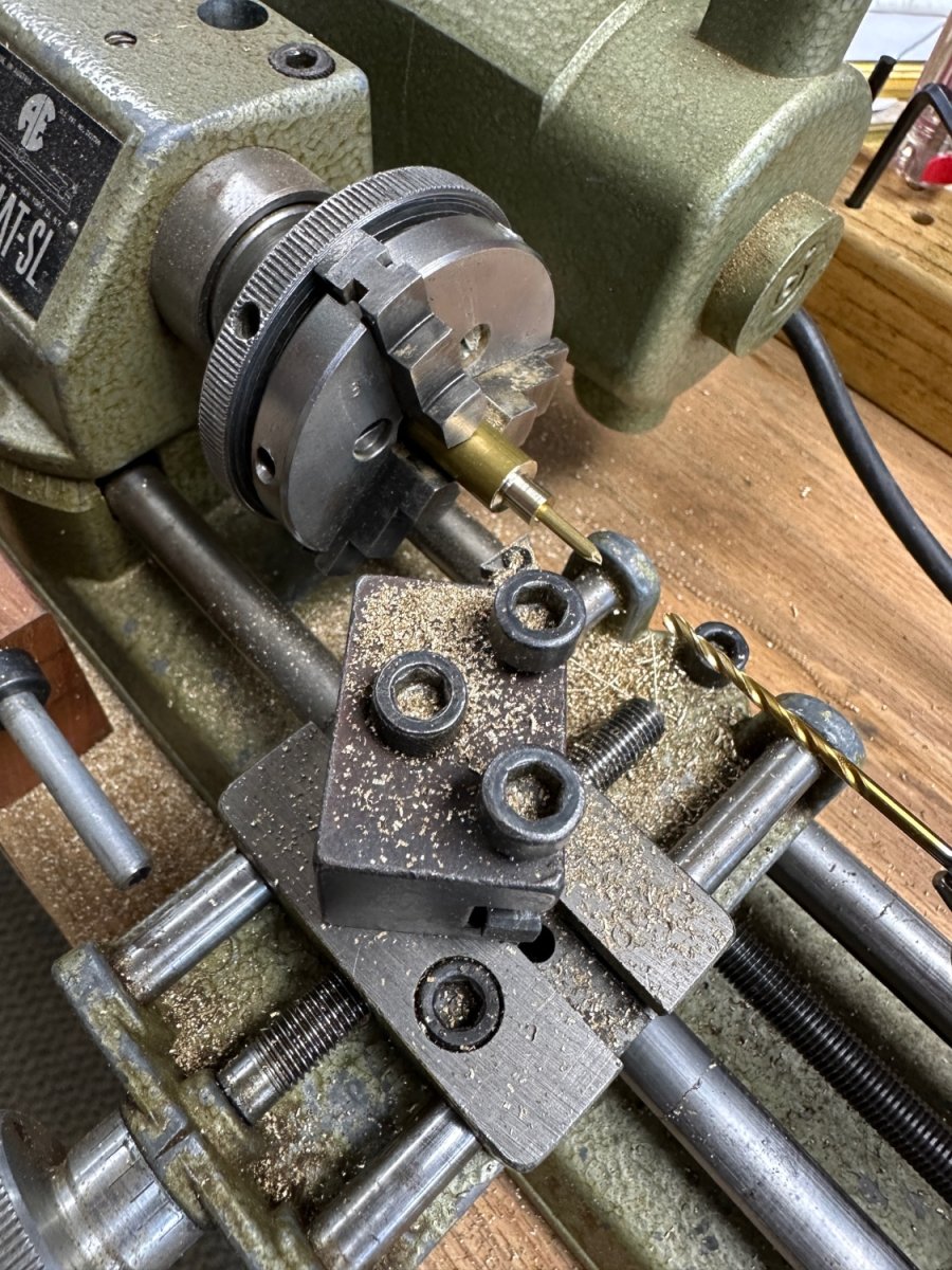
Lathe setup. Drilled the stock to the pipe size, and then machined the body. Then I will cut a disc and attached it to the body with a proper size stem.
On this valve I started with some old 3/8" rod stock. But now I found the 3/32" rod that will make the machining easier.
Stay tuned.
-
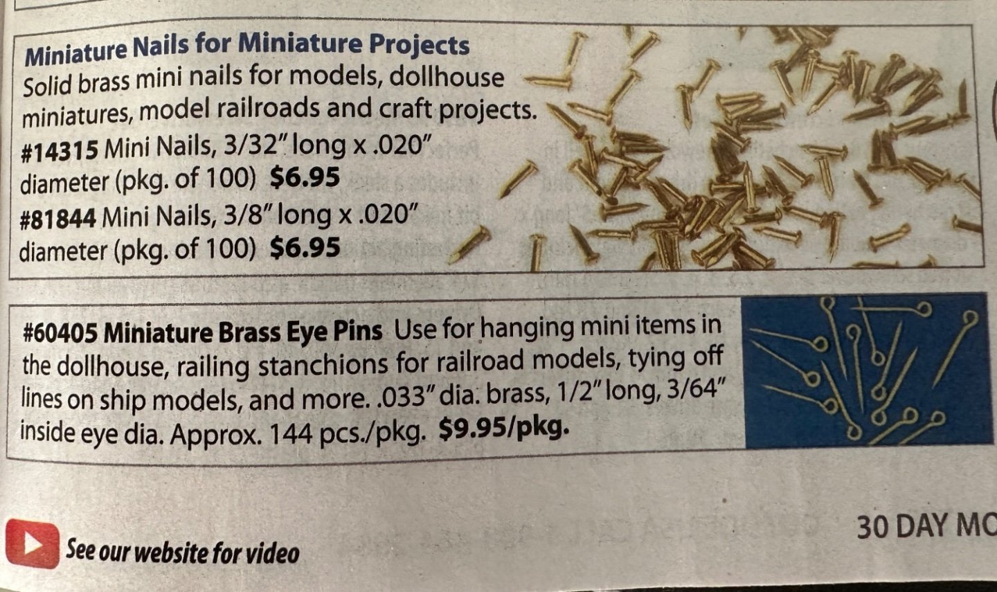
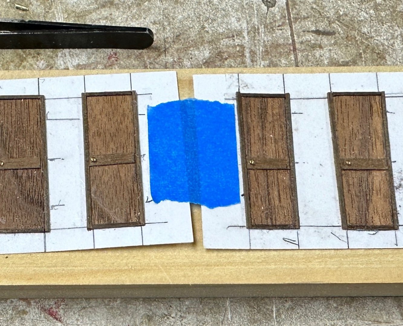
Valeriy, I used brass mini nails that are sold by Micromark in the US. These nails are sold to temporally fasten planking strakes in the model frames. I have a supply of them. They have round heads and I set them on holes filled in the door but leave a little of the stem out. I also used other sizes using sewing pins.
Now I am trying to figure out how to made the lever type door knobs to use on the other doors of the model.
Thanks for your comments and likes.
Any ideas?
-
Outstanding work. Olympia is one of my favorite ships. You have done a splendid job. Congratulations
- Canute and Ryland Craze
-
2
-
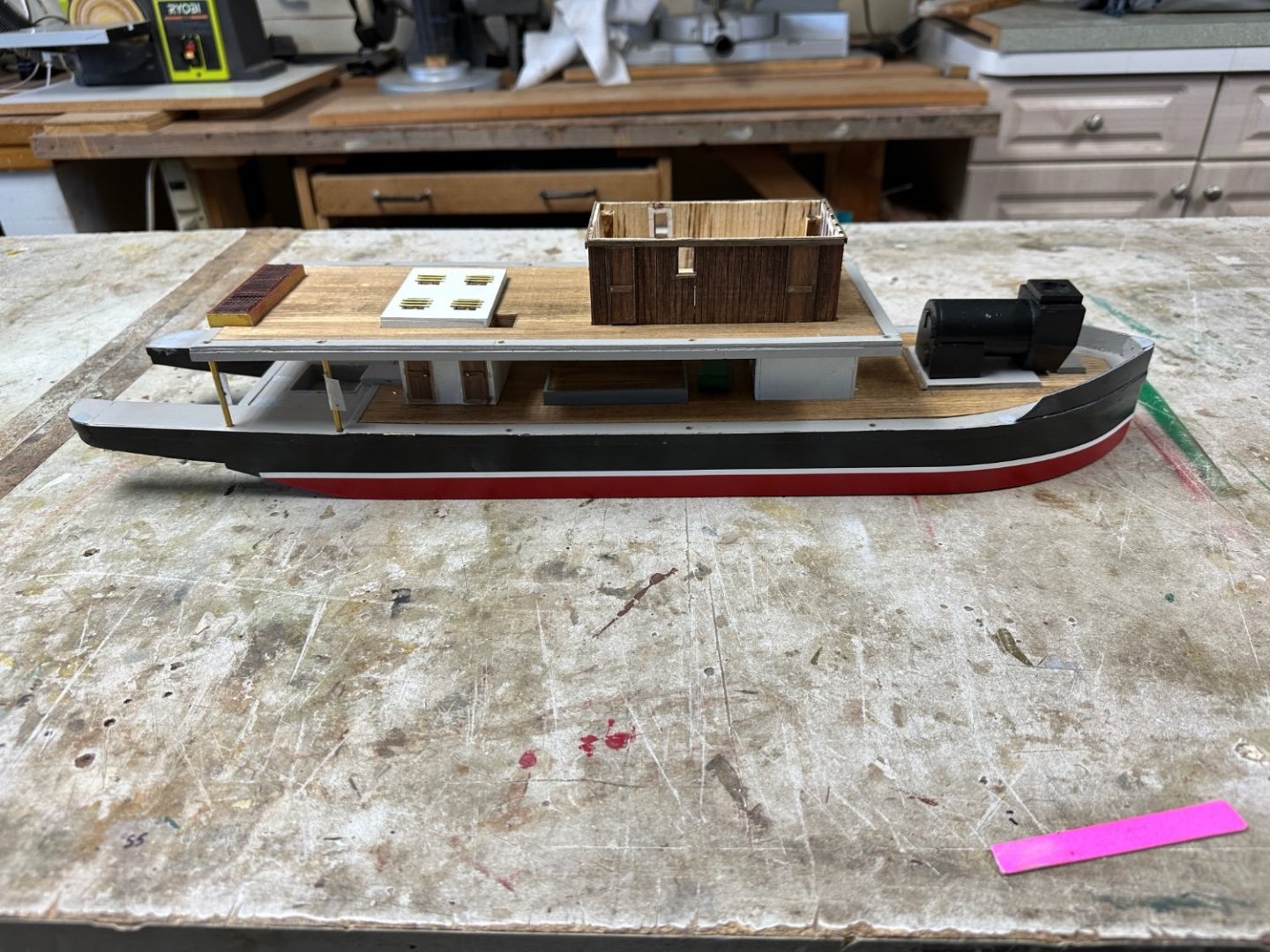
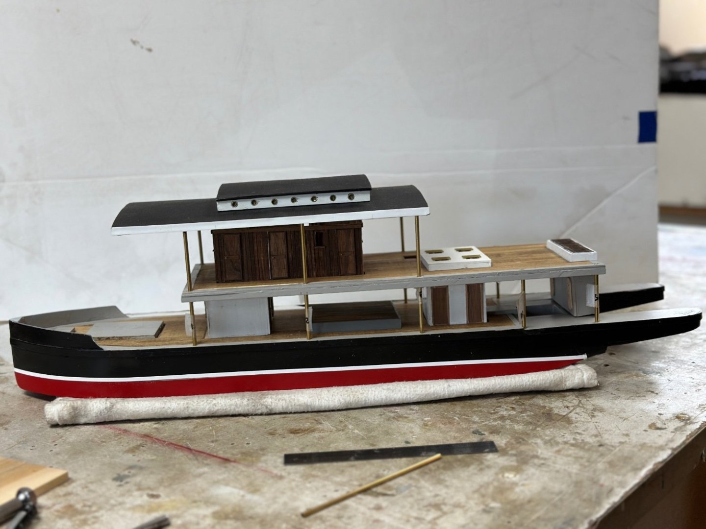
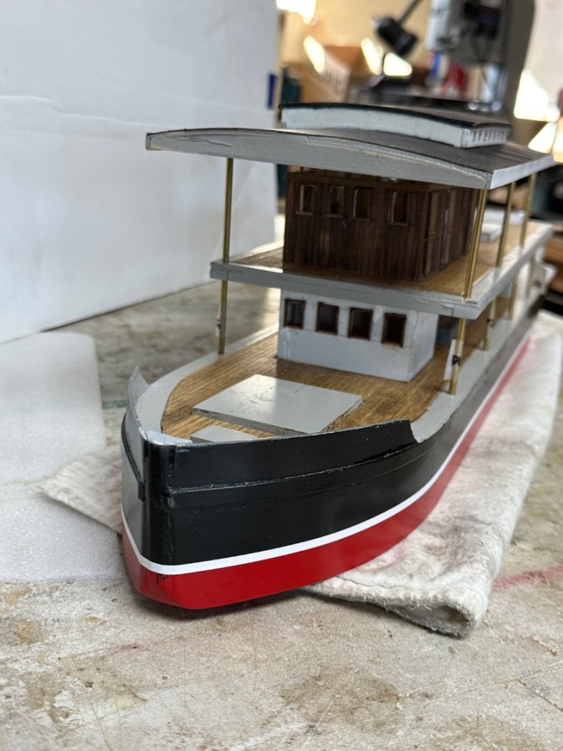
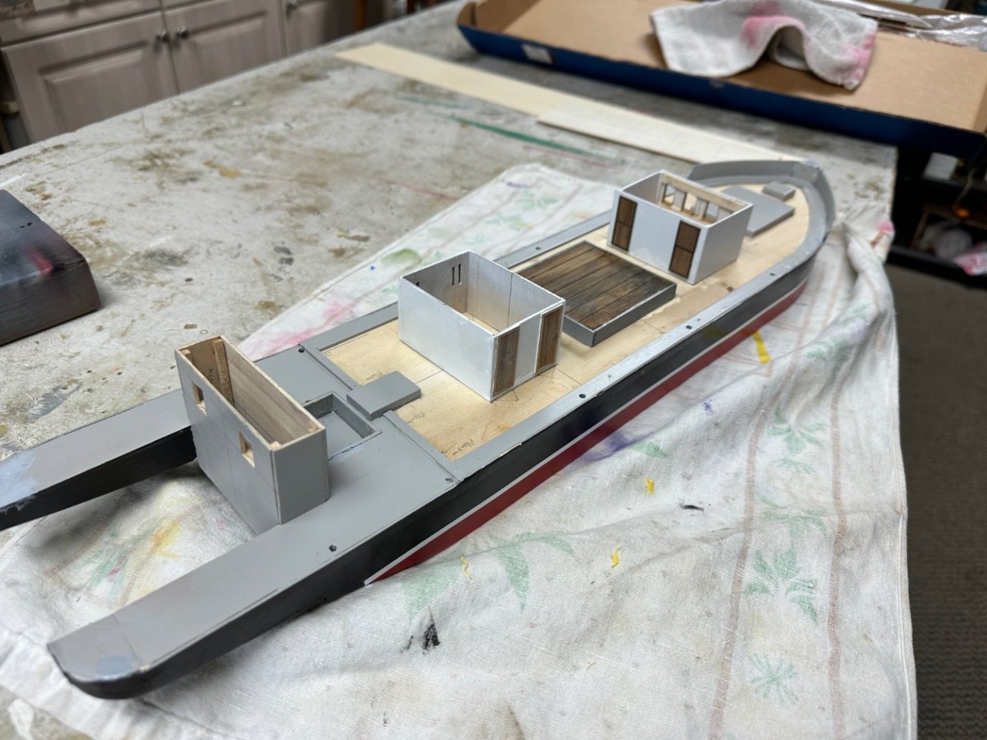
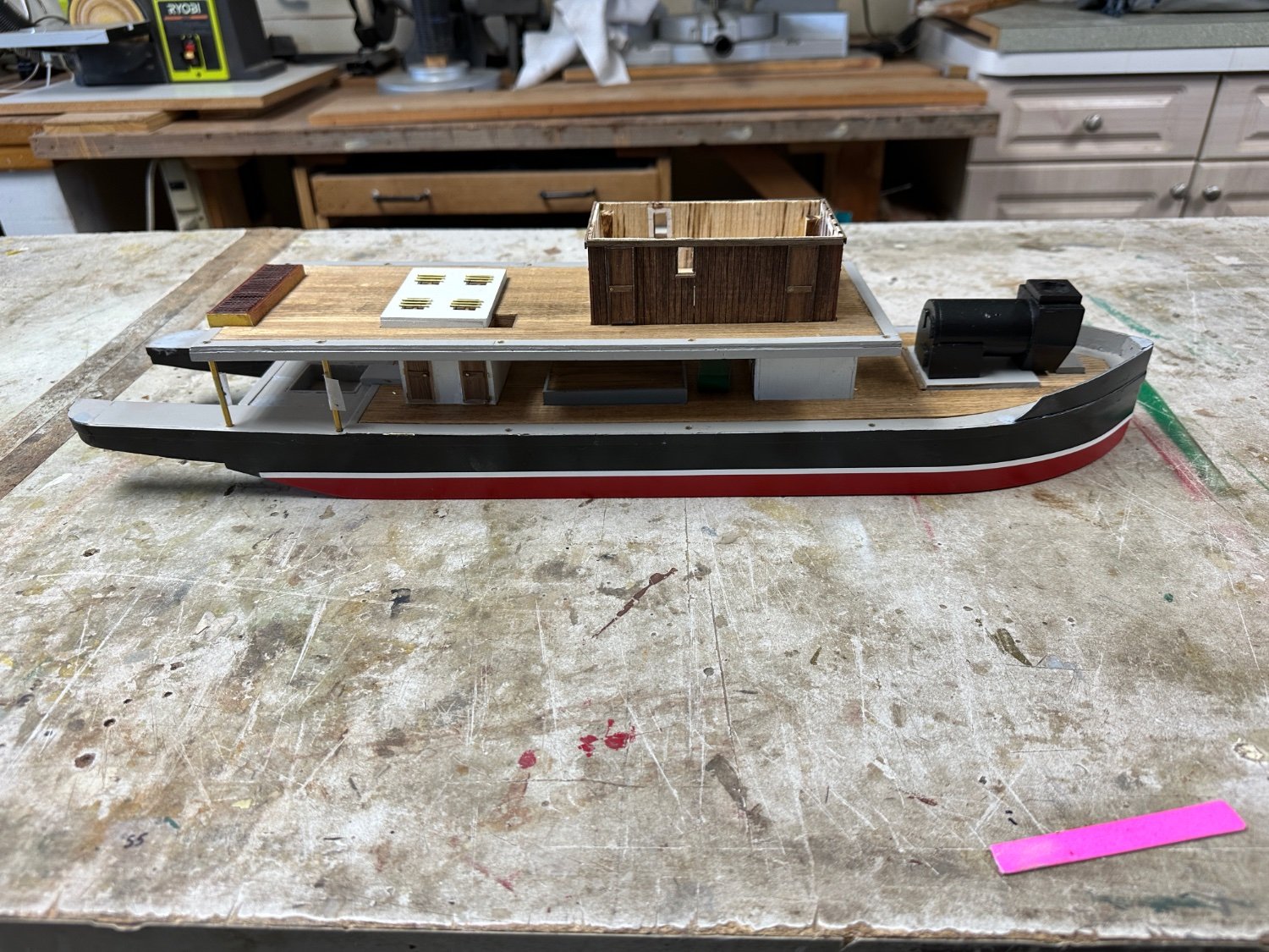
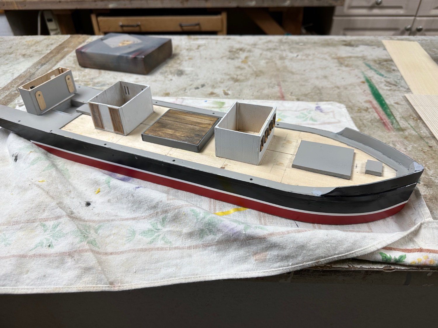
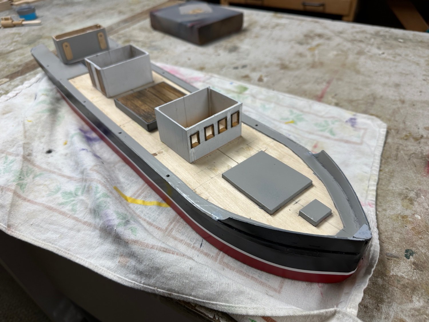
Completed the rest of the superstructure. A few little details were left out since I am anxious to start building the propulsion system. Dry fitting all the parts, I assembled the ship.
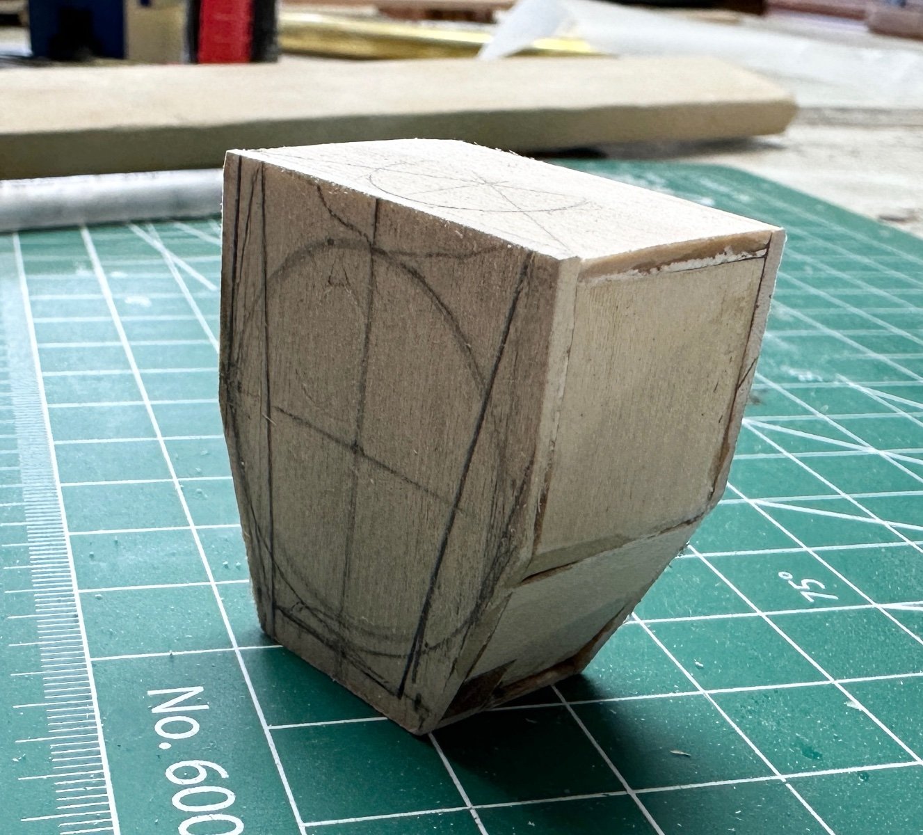
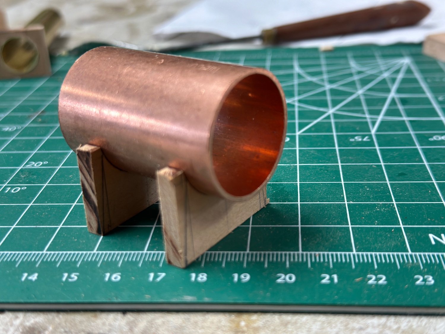
Then, started work on the boiler. First, the smoke box.

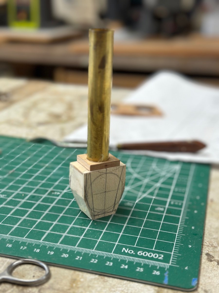
Then the stack.

Followed by the boiler.

And this is the dry fitted boiler.
I have also been following Cathead's build of the Peerless. Very interesting and informative. As a mechanical engineer, whose work was mainly in the energy systems, I enjoy the debates about insulation, expansion loops, superheaters and steam traps on the piping. But at the scale I am working it is hard to include all the minuscule parts that would make the piping correct.
Thanks for watching and I enjoy your comments.
-
calt4, welcome to my build. It is a lot of fun to scratch-build a model. In addition to figure out how to fabricate a piece you also have to figure the right sequence for the assembly is also important. For instance, in this model, I assembled the walls of the cabins and then have to open the windows on the finished cabin. It would have been easier to build each wall independently and then assemble when completed.
-
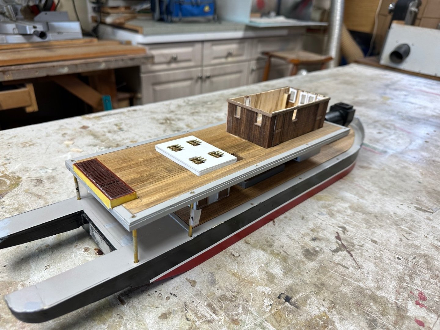
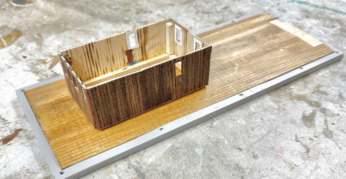
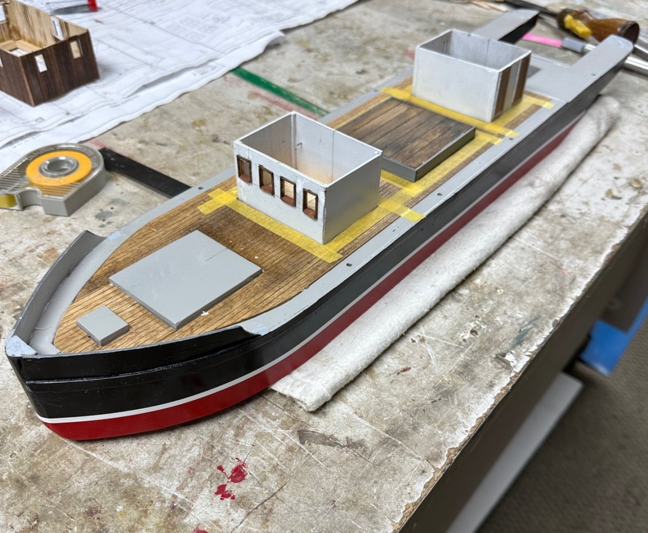
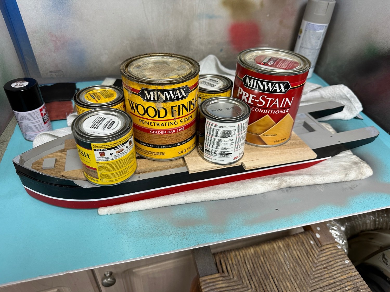
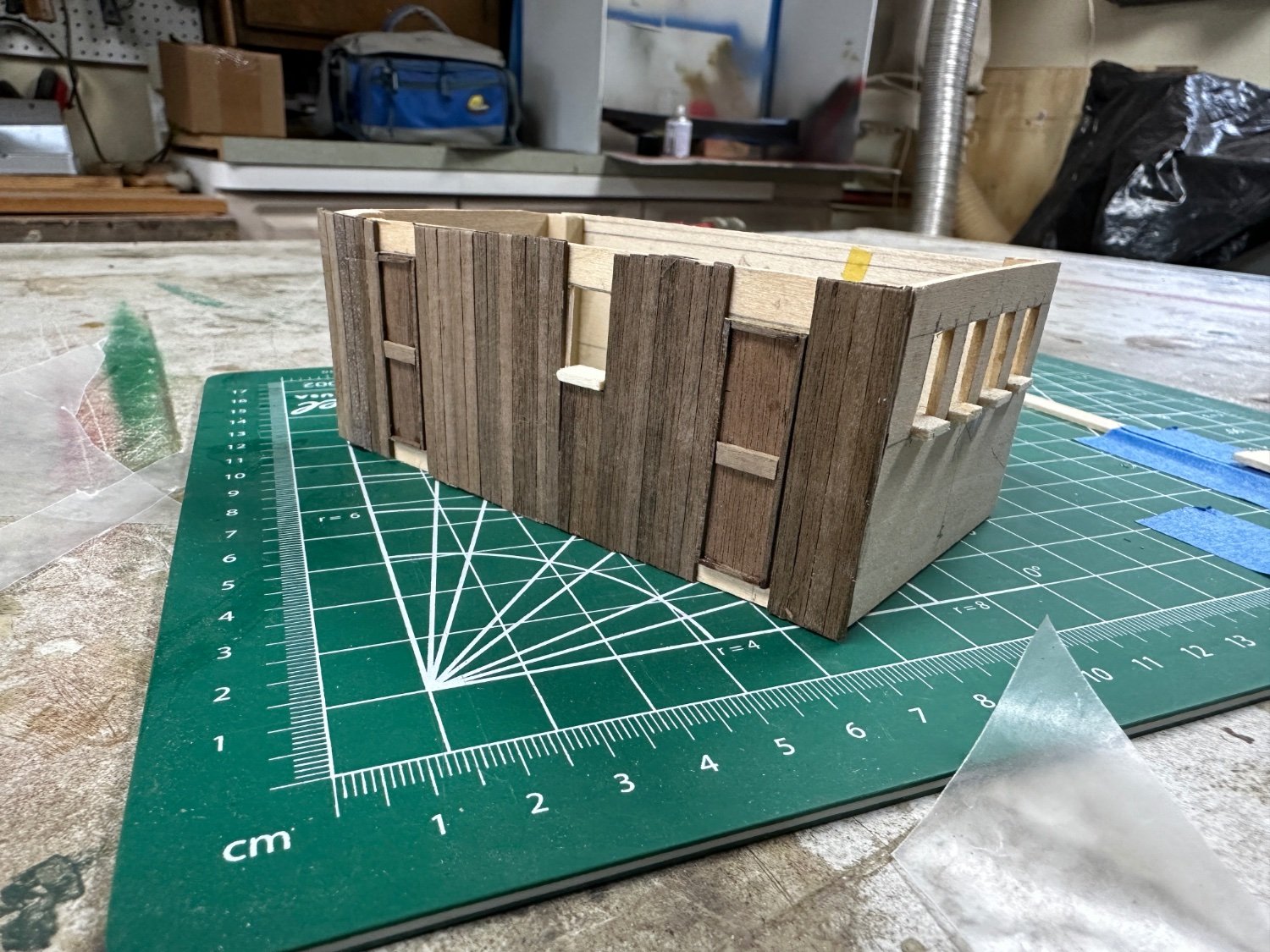
Little more progress. I didn't like the way the passenger cabins came out while using plain walnut strips as shown in my previous post. According with the information I had from the article in Model Boats, these cabins were built in mahogany; so, I bought already scribed basswood boards and fabricated the new cabins. I used a mahogany stain and the results can be seen in the photo, shown here on top of the planked boiler deck.
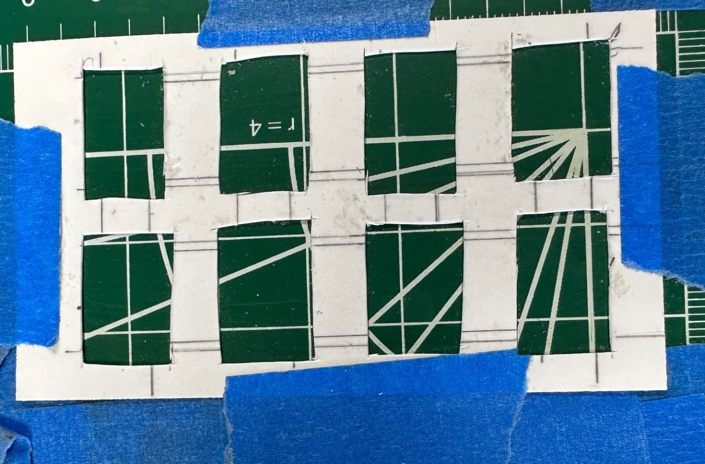
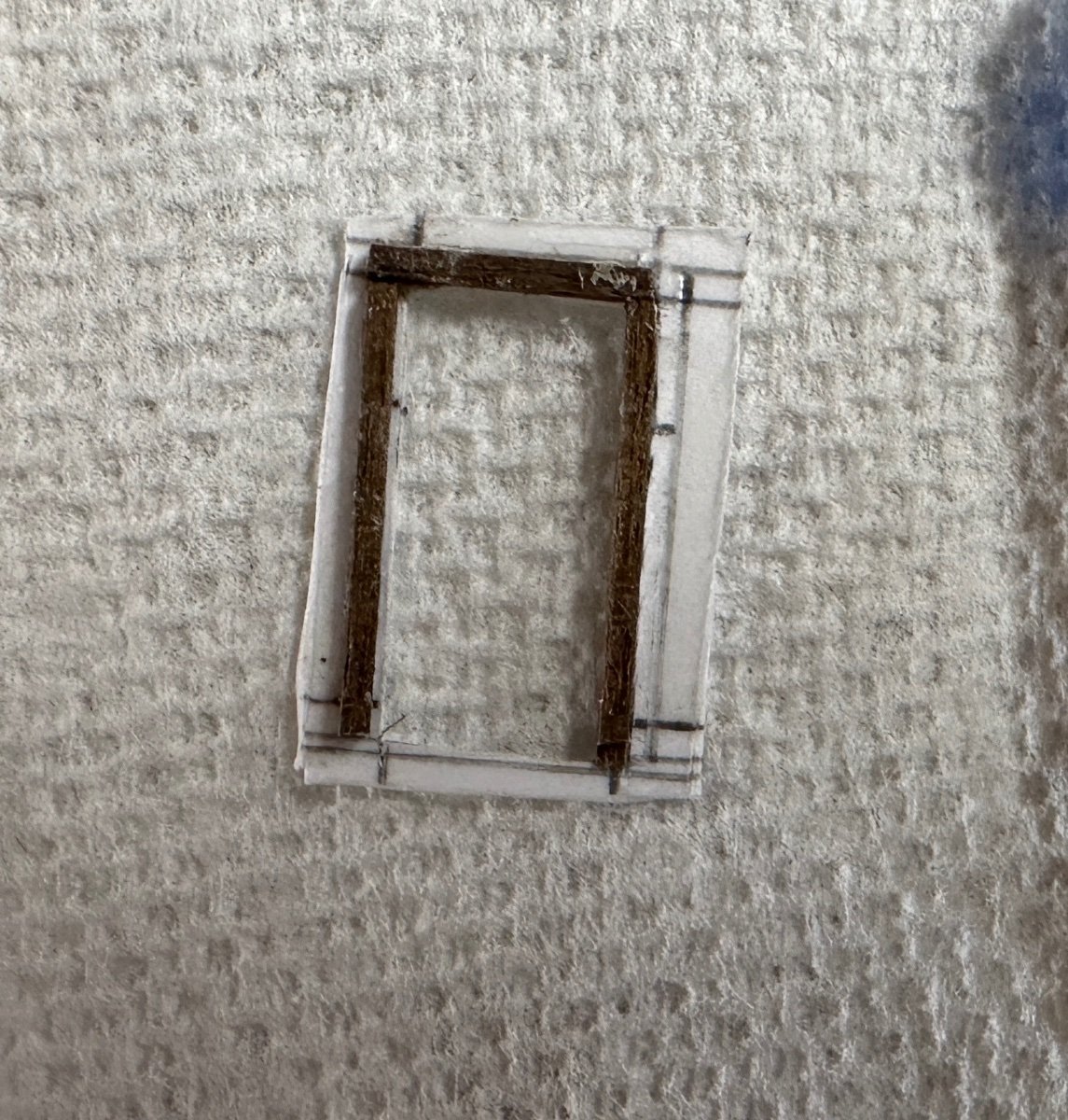
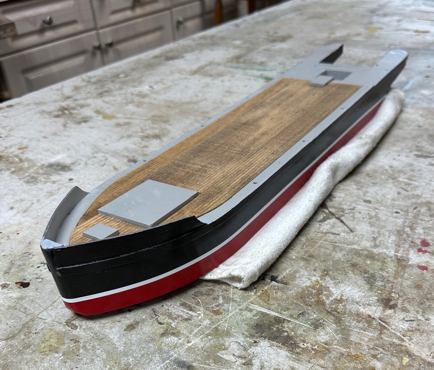
I used the same type of pre-scribed board to do the main deck and the boiler deck planking. I also developed a method to make the windows. Basically, I drew the them in card stock and glued the minute frames to the cardboard and then cut the opening. The window was cut oversize from the card and glued to the opening in the walls of the cabin. You can see the the card stock in the inside walls of the cabin above.
The window glass (acrylic) will be attached to the inside of the frame. I used a similar method to make the varios doors. The finished doors will be glued to the outside planking in the cabin.
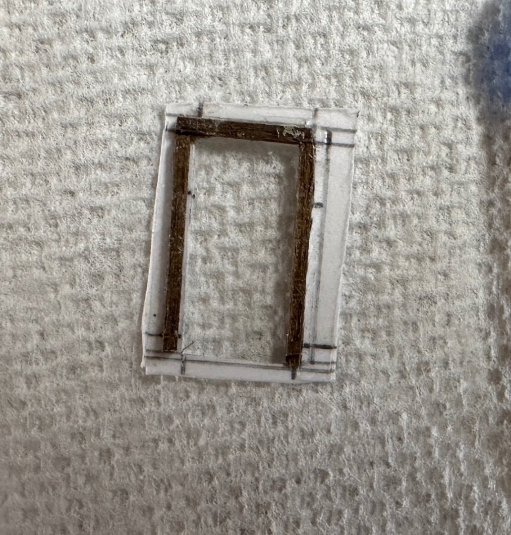
Forgot the scale match but the window is 12 mm wide.
The doors had a similar treatment.
Completed the planking in the main deck.

Have already finished the roof but have no pictures yet. Getting closer to the mechanicals.
- yvesvidal, GrandpaPhil, Valeriy V and 2 others
-
5
-
-
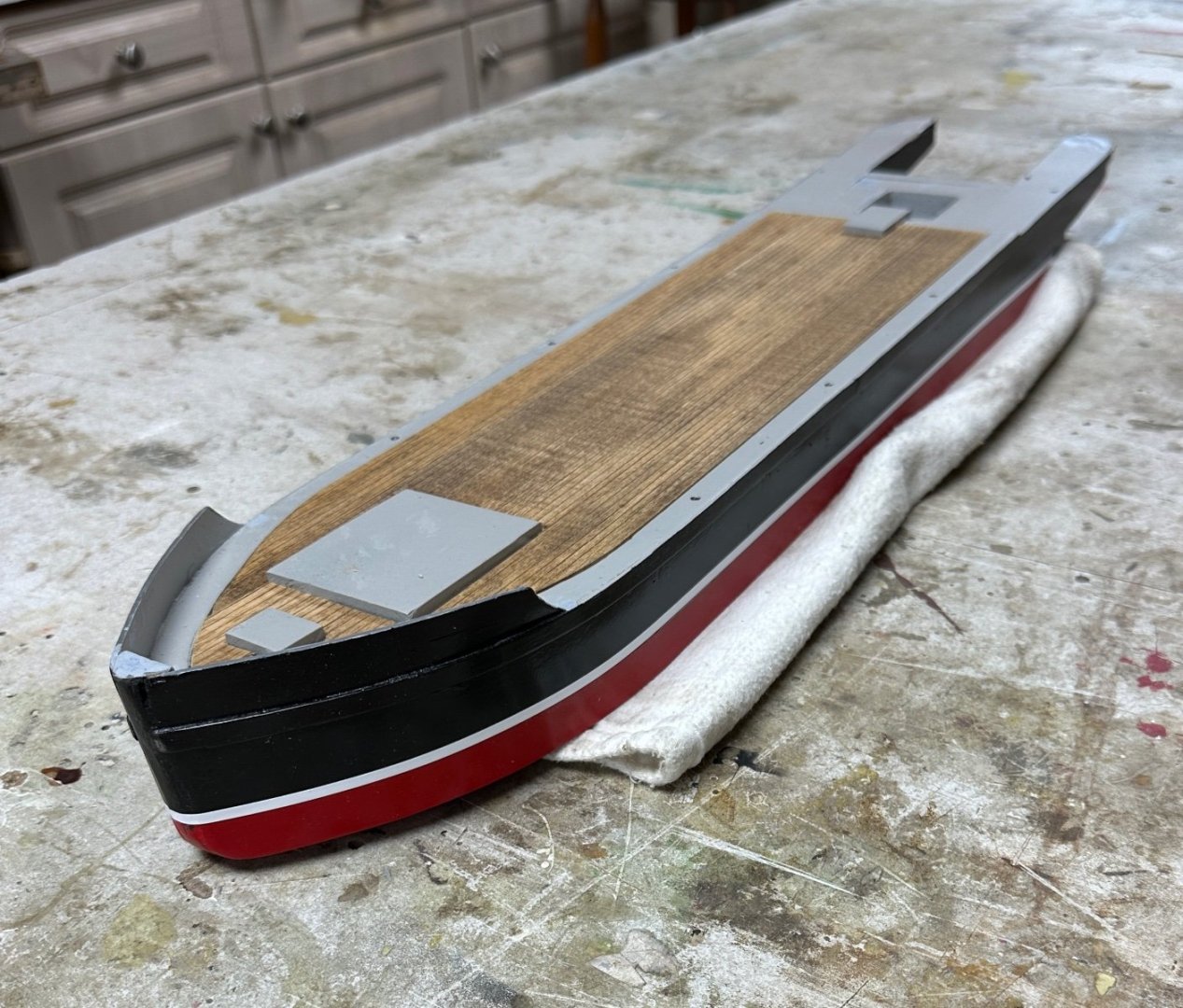
A little more progress. Painted the hull and completed the lower cabins. Getting ready to start the main deck planking. Had a little trouble with the main cabin in the boiler deck. Have tried several methods to display the mahogany planked walls using very thin strips. The results don't look good since the grain shown is so apparently out of scale. Decided then to fabricate the cabin using striped basswood pieces.


- kgstakes, KeithAug, GrandpaPhil and 3 others
-
6


SMS WESPE 1876 by wefalck – 1/160 scale - Armoured Gunboat (1876) of the Imperial German Navy as first commissioned
in - Build logs for subjects built 1851 - 1900
Posted
Wefalk, my next model is going to be the SMS Temes (aka Bodrog) from WW I in 1/64 scale. I will use your system to develop the naval ensign of the Austro-Hungarian Empire. Thanks for your craftsmanship. It is definitely an art.