


Ras Ambrioso
-
Posts
592 -
Joined
-
Last visited
Content Type
Profiles
Forums
Gallery
Events
Posts posted by Ras Ambrioso
-
-
I just ordered the plans for Zulu from Sarik Hobbies and will be using your 3D drawings to scratch build the model. There is not much information online for this boat. I will start the build log as soon as I get the plans fro the UK. Great job bringing all these details to live.
-
Great job. The only thing missing are the flowers. Maybe you could get some miniature flowers. You may try the net for places that sell material for doll houses. Here, in the USA, we have Hobby Lobby and Michael's that carry such stuff.
Pero, en todo caso tu trajinera es bella.
-
By the way Jacques, are you also a diver? I used to dive in Cuba with the aqualung just after Jacques Cousteau wrote his famous "The Silent World".
- mtaylor and Glen McGuire
-
 2
2
-
Jacques, I am enjoying reading about your journey through you first scratch built. Your story telling is great and told me about a few things I didn't know. I have have been in Mexico City in many occasions and had the pleasure of enjoying the rides at Xochimilco. The one thing that was notable in the "trajineras" at the park was how colorful they were. Flowers all over and brilliant colors. I will be following your build.
Que viva Mexico
-
-
Well I finally cooled down from my disappointment at crashing my, almost complete, model. I used this time to embark in another project which I will be logging soon.
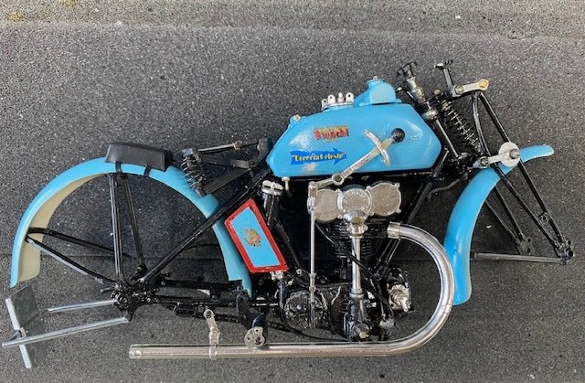
As I have shown before, the breakage included the connecting pieces between the frame and the front fork. Rebuilding these parts seemed an easy job and I decided to use some styrene strip that I had left from the Mimi project. I needed 4 pieces that had to be exactly equal since they formed the parallelogram that allows the movement of the front fork with respect to the frame.
In order to make four similar pieces I decided to glue four strips and work the drilling and shaping in unison. I would use Elmers glue and, when the fabrication was completed, I would de-glue the strips with alcohol. Great idea, Ras.
This was the test of the process.
Then I dipped the bunch in the de-gluing liquid.

The next day I removed the bunch from the liquid and ...... Horror again. I had a melting goo instead of four nice separate strips. A little investigation resulted in finding that I had used acetone instead of alcohol. Another senior moment.
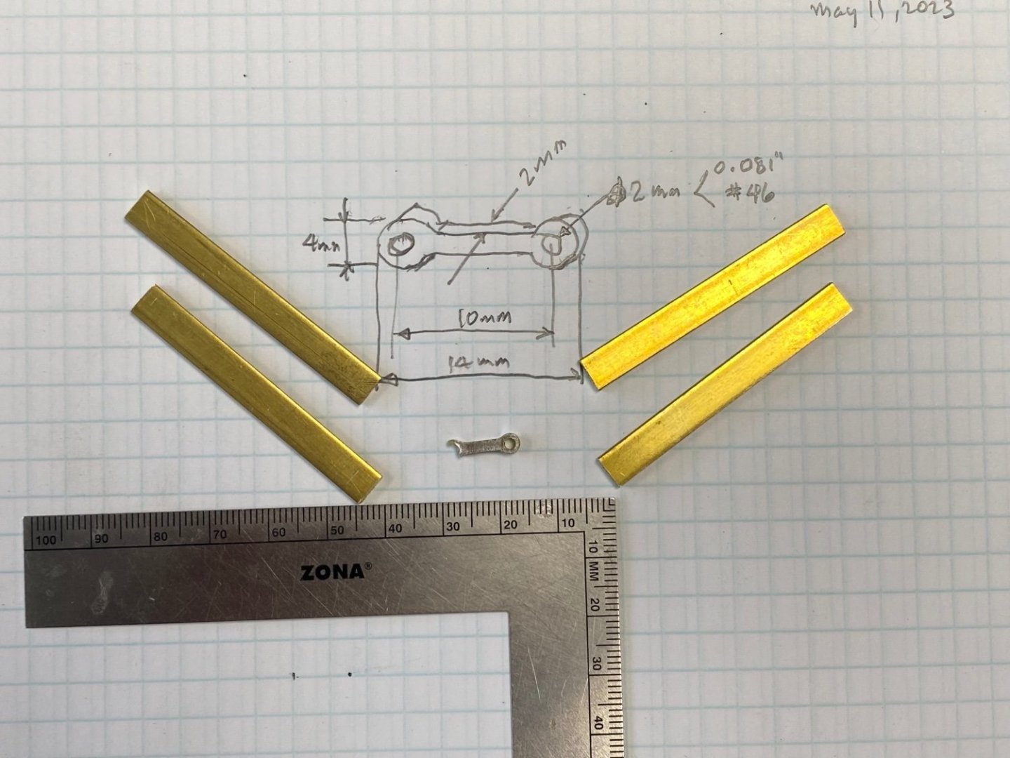
Then I reconsidered the problem and decided that metal would be a better material for this stress are in the bike. Using the the same idea of fabrication in unison I could use superglue to bind them during the drilling and shaping and then use the acetone to separate the pieces. Great!
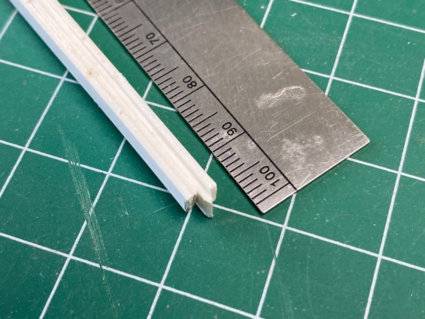
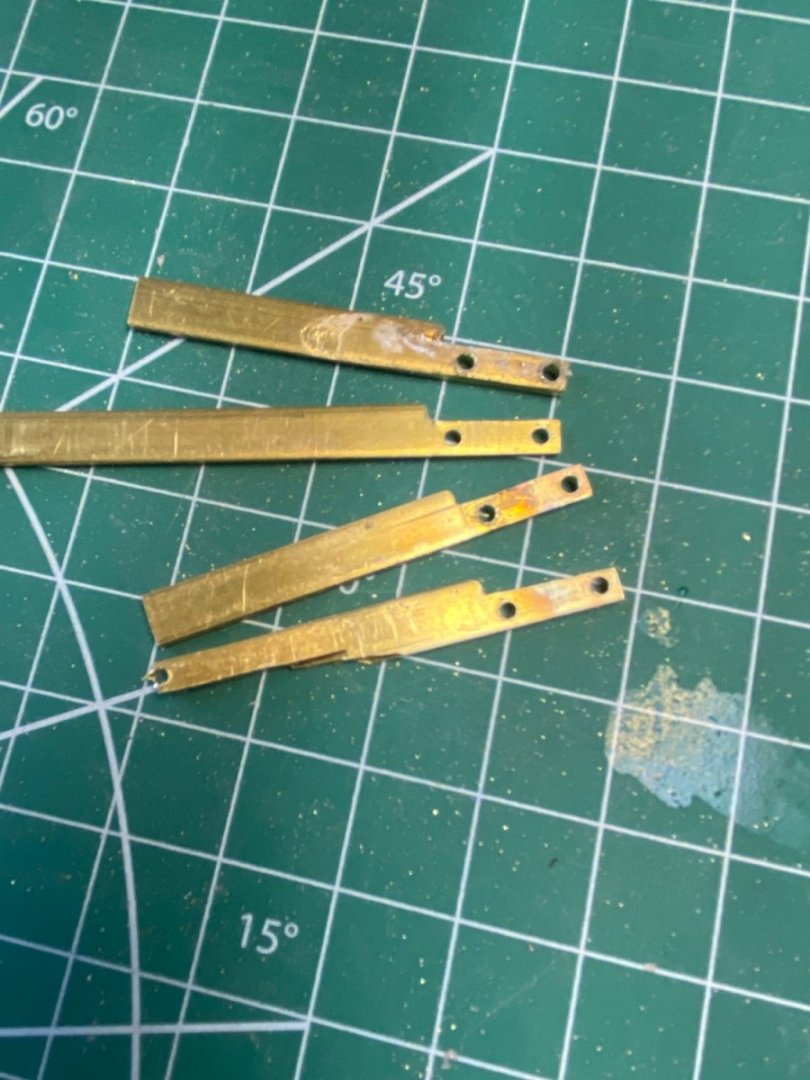
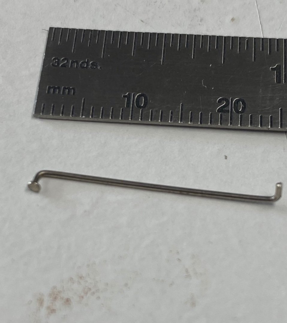
I measured the connector and cut four pieces of brass strip 6X2 mm.
As planed, I glued with CA and let them in the vise overnight.
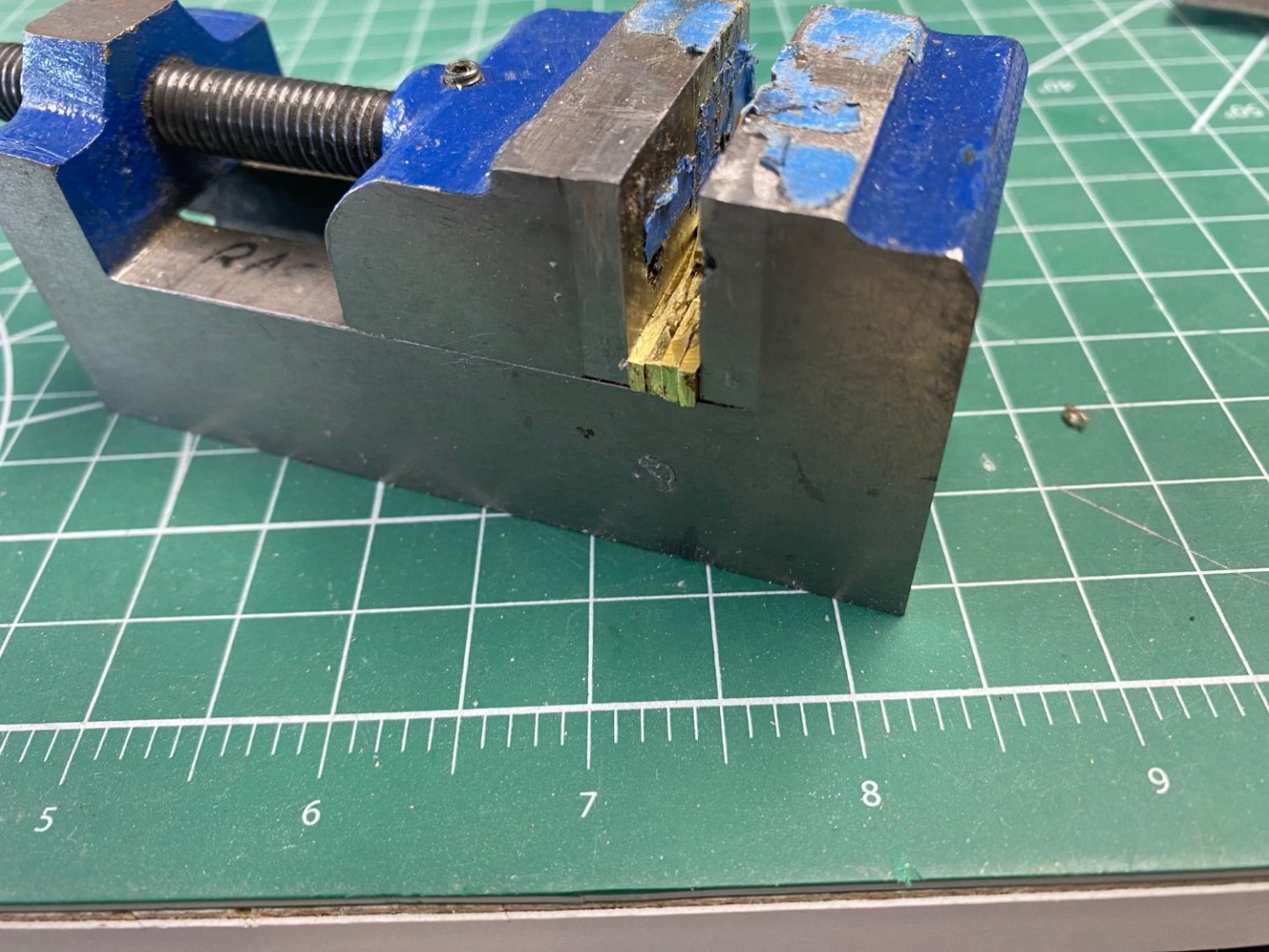
Then with a file I brought the bundle to size marked the holes and starting the drilling of the two holes. Now, guess what........ Horror again. The heat of the drill unglued the strips and ruined the job. I then started again with a new set of strips and this time I clamped them together during the drilling.
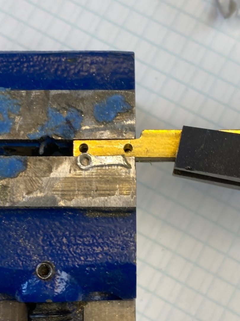
And yes, finally, success:
Now I will shape them using my hand tools. The saga continues, next comes the handlebar and the bottle of champagne.
-
Fantastic. I see you found the scale match LOL
- Keith Black, Valeriy V, mtaylor and 3 others
-
6
-
Thanks for the encouragement, guys. See you soon.
- mtaylor, Canute, Old Collingwood and 4 others
-
7
-
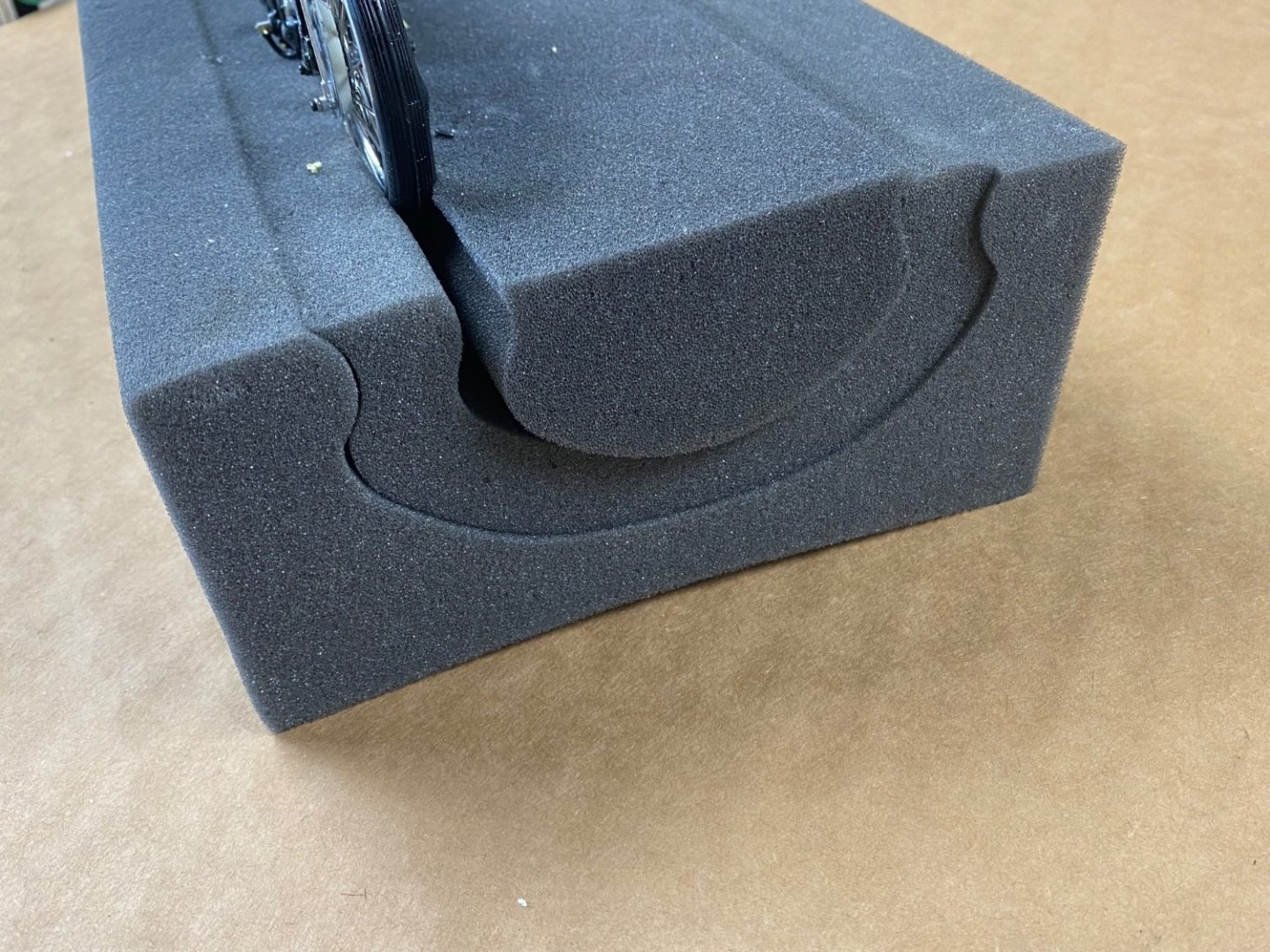
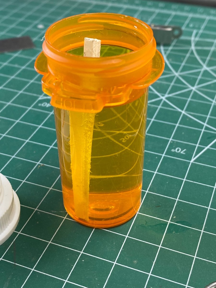
While I was working on the finishing details of the motorcycle I was using a block of foam that I bought from Micro-Mark. This block was used to hold the ship's hulls while working on the superstructure. I found that I could lay the motorcycle on the top of the block setting the foot holds in the crack. The arrangement worked perfectly. Now I am ready to install the completed handlebar (See Post #28) and attach the control cables to the ignition, shift and brakes. So I figure in using the same block to stand up the bike.
Here is the bike in the block:

Here is the end view. The block is precut to use on three different size hull beams. Very useful tool.
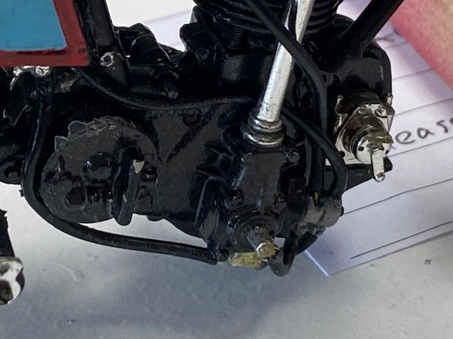
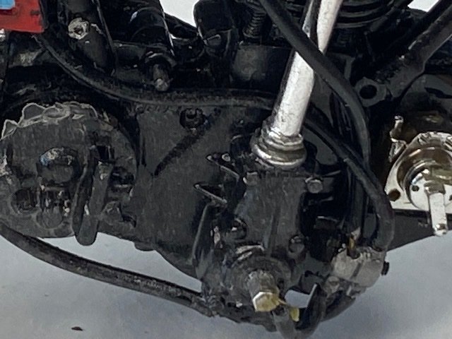
Then disaster struck.
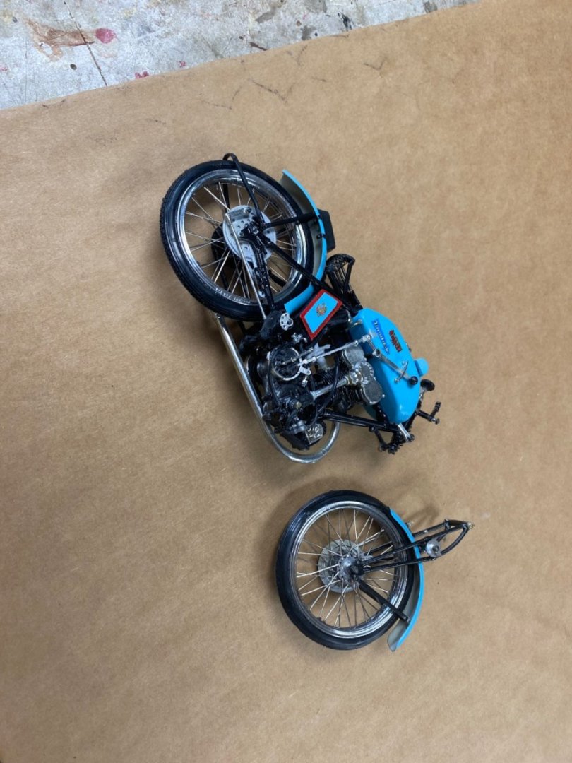
While changing the bike's position for the photos, I dropped the bike and the "Bianchi Curse" struck again.
I have tried to build this bike since the 90's when I built the spoke wheels and found the kit quite difficult; so, I abandoned the build and put the kit away. Then,in 2017, we downsized and I got rid of most of my tools and kits. In 2021 I found the same kit available online and proceeded to purchase it at quite a high price. I decided to start in another place other that the wheels. At that time, I assembled the frame and painted all of the body parts in the sky blue color. Then, when I joined this forum and started building ship models, I put the kit away . The kit sat in a shelf in my closet. This year(2023), while searching the forum, I found the "other than ships" section and my interest in the Bianchi was reborn. And now the "curse" hits. It seems that I am not supposed to finish this project. But, if Valeriy can work his magic in his hometown situation, I can rebuild the broken front end too.
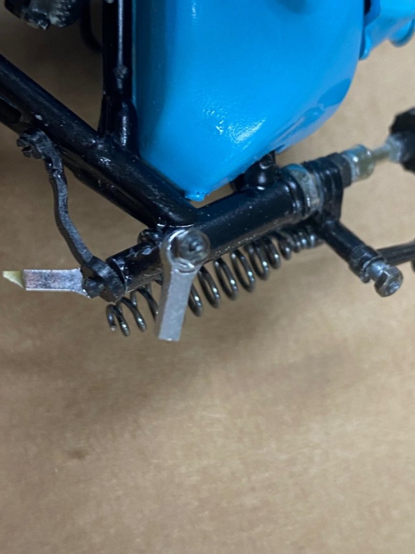
As you see on the last photo the front fork broke at the suspension parallelogram. I will use brass to rebuild the four connecting bars. I am going to take a couple of weeks to cool off working on another kit model (a B17F bomber in 1/72 scale).
See you soon
-
-
Congratulations.
1 hour ago, CDW said:There are almost always additional things that could be done. But hey, there are too many models and too little time so I must move on now.
Fantastic job CDW and agree with with that there is a point when you have to stop and move on.
-
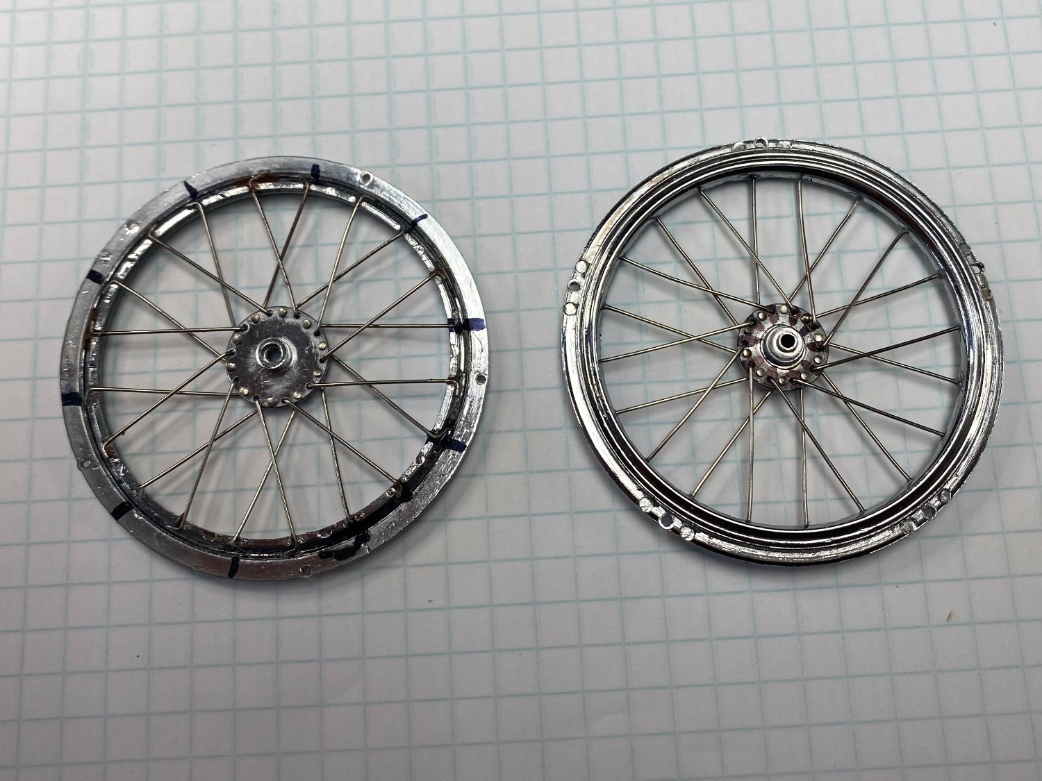
Nothing better that hear from experts. When I was assembling the two halves of the spoked rims I looked for any markings that would have been included tor the correct assembly. I didn't see any, so I proceeded to eyeballing the setup. If I was making this model for sale or museums, I would unmount the wheels, unscrew the rims (5 mini screws) and rotate the rim one hole. But, I am going to let this go as is. If you look closely at the overall assembly you will find a bunch of "oops". Building this model has been frustrating, tedious and incredible difficult considering my shaking fingers, bad sight and lack of five hands. But I have loved every minute of it and enjoyed sharing my experiences with the forum.
- Ryland Craze, Canute, Keith Black and 9 others
-
11
-
 1
1
-
Excellent point Mark. The floor is the top of our well used bench and the wall is a sheet of poster board. But the bike does look real. I wish I haven’t painted the whole engine black because the details are incredible. Thanks for the comments and likes.
- Keith Black, Canute, mtaylor and 2 others
-
5
-
-
-
-
-
Amazing work. I smile when I think of your tolerance of 0.008 mm when mine is about 0.500mm. Its a real pleasure to look at your work.
- mtaylor, FriedClams and Keith Black
-
3
-
-
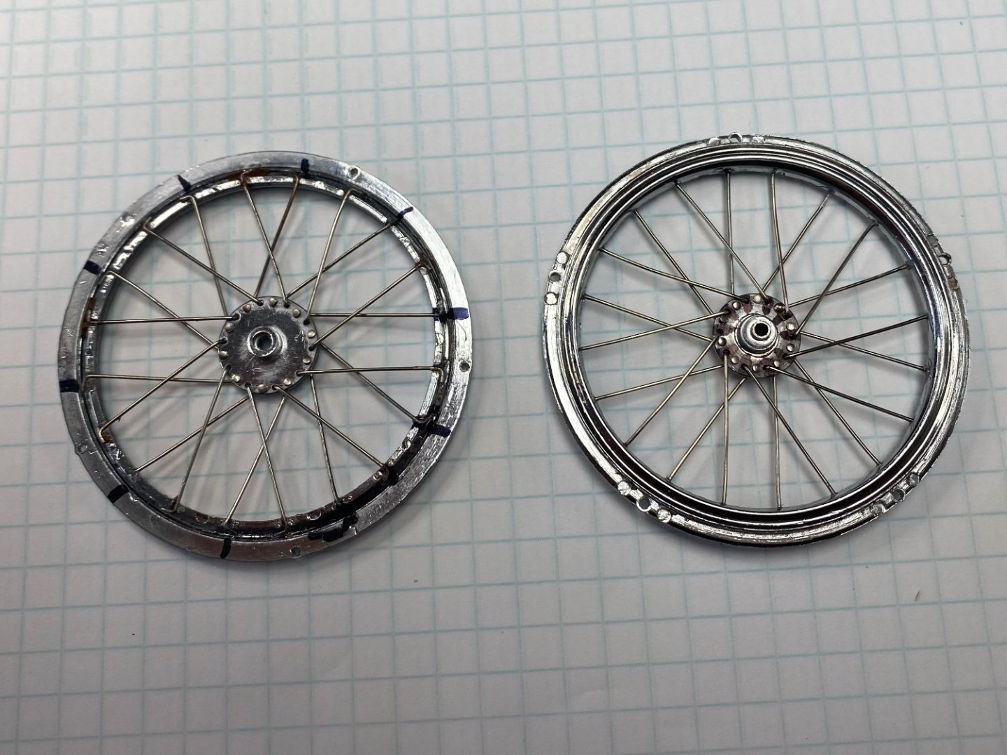
Finally, after three days of work, (a total of 10 hrs, really), the first wheel is done. To set the tire in the rim I had to recall my experiences as a teenager removing car tires off their rims to fix the flats. Working part time in a garage, the only tool available was a steel bar and a hammer. Here I had to use very small screw driver to open up the tire an let it slip on the edge of the rim. As everything else in this build, a very frustrating experience. But I loved every minute of it.
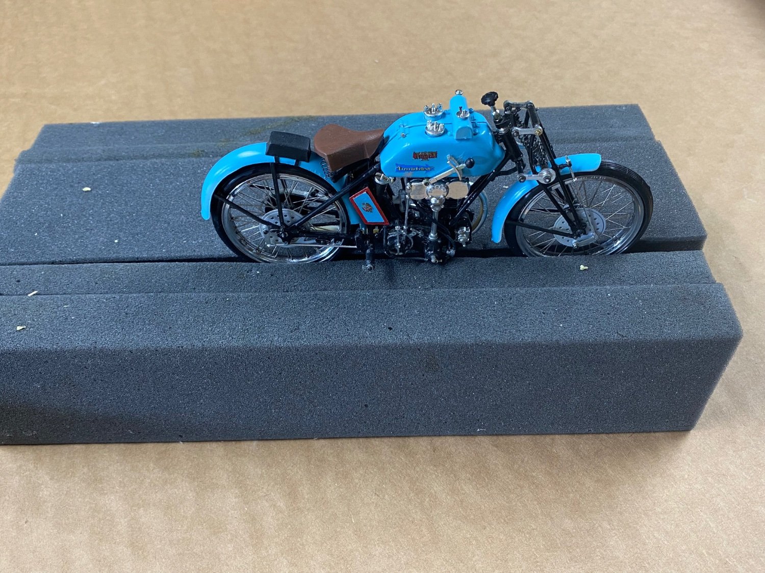
After a wait of over 30 years I, finally get to see this kit nearing its completion.
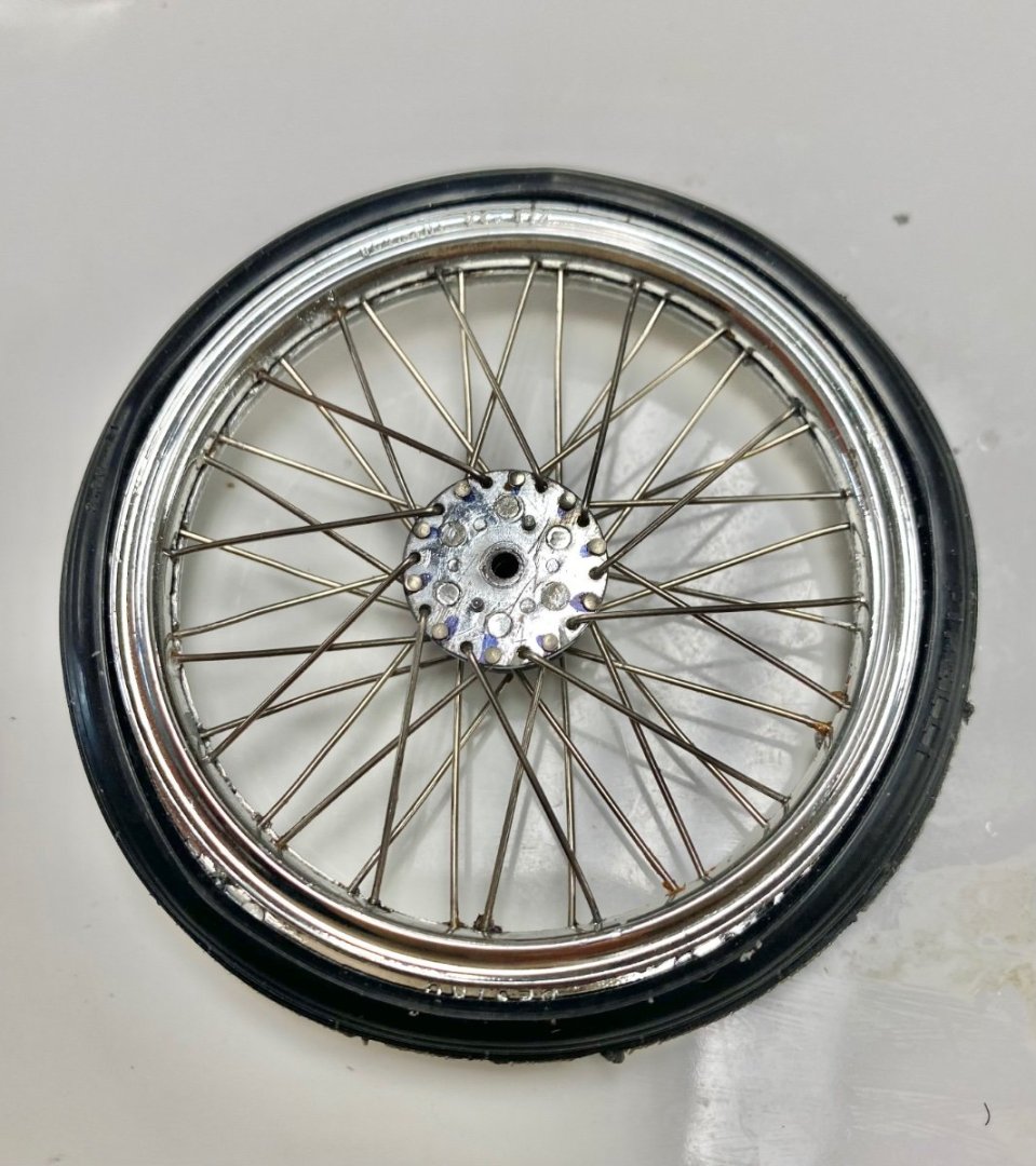
Notice the detail on the tire itself: Pirelli.
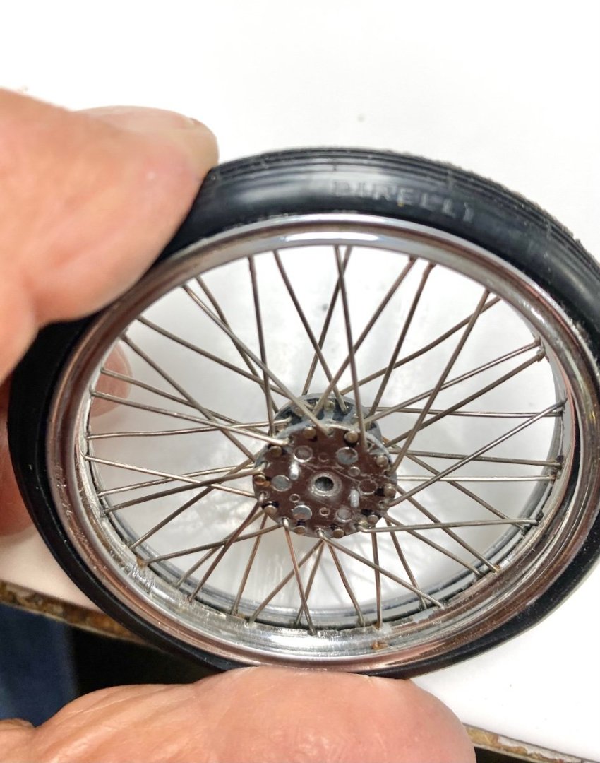
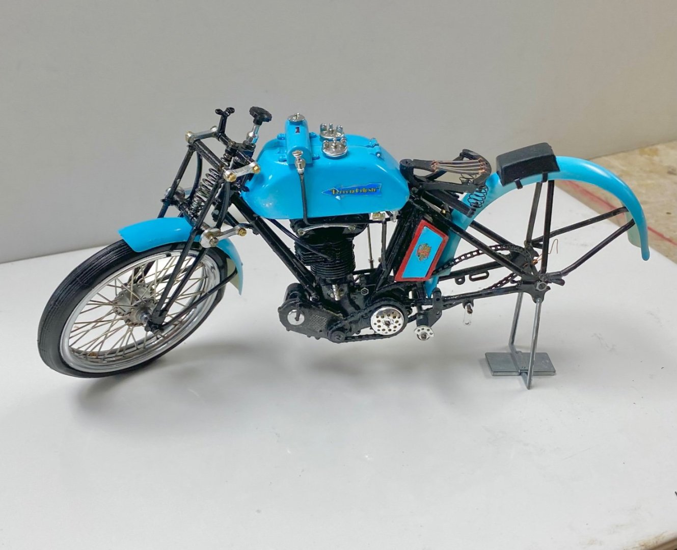
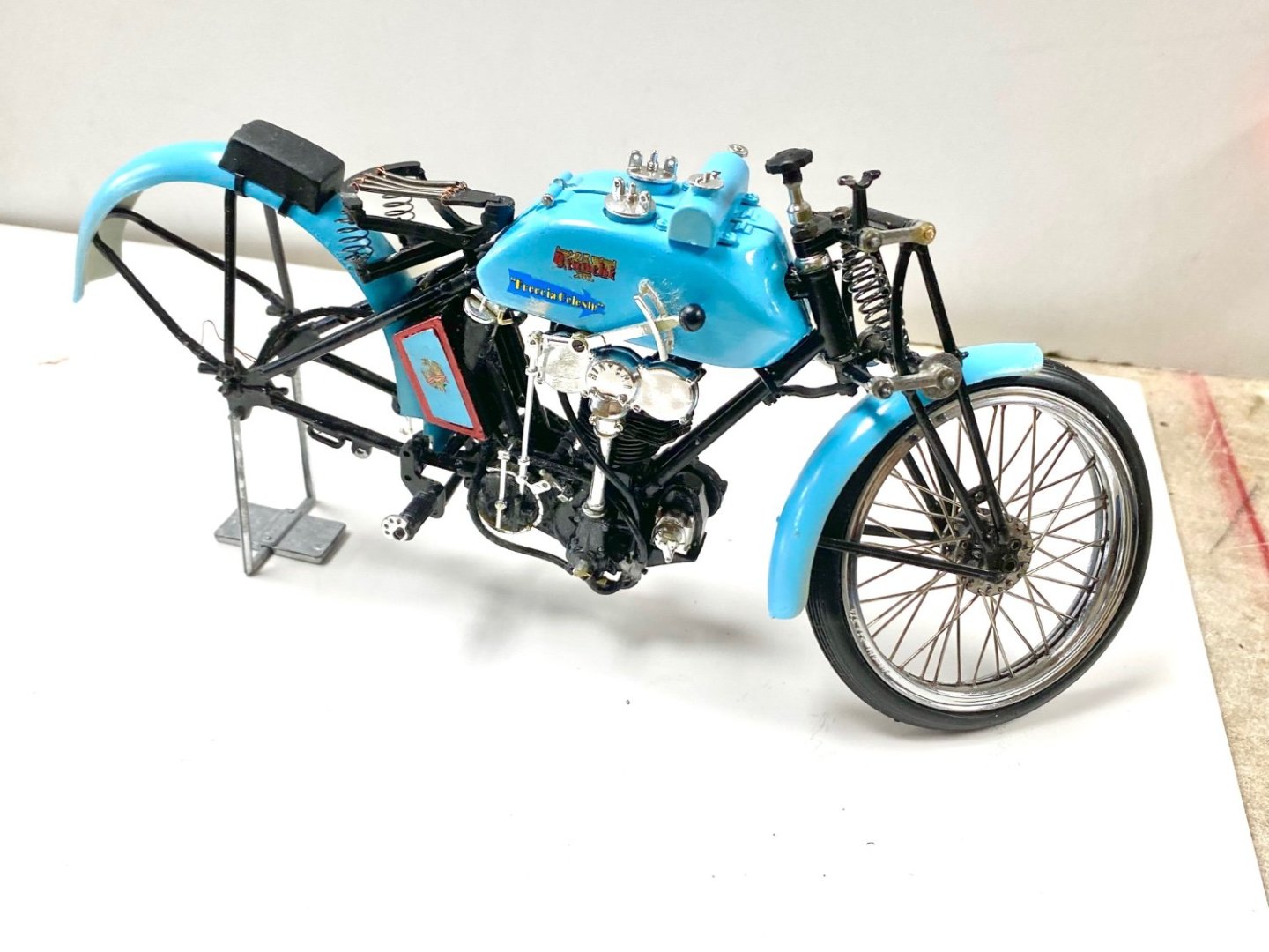
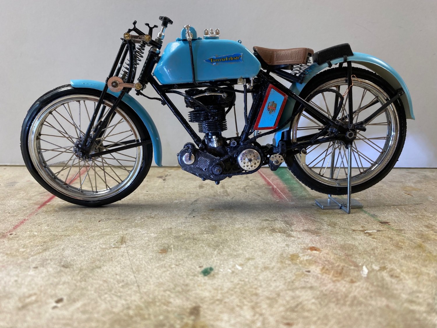
And this is how the Bianchi looks now.
-
Well, the day came that I had to start assembling the spoke wheels. I have dreaded this moment since I had failed before in my attempts to build this kit back in the 90's. At that time, I started with the wheels and got totally frustrated and abandoned the project. Now, that I am older, I think that have gained some patience and perseverance to deal with failures.
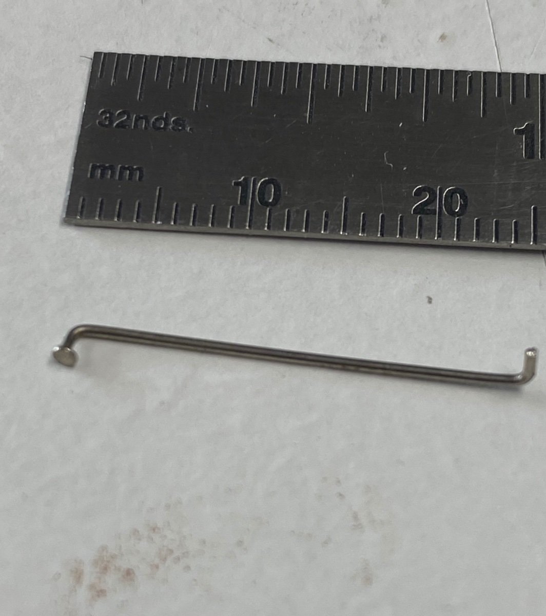
I purchased this kit used. It seems that the previous owner had started the wheels and had fabricated the 80 spokes necessary and then quit. So, for the start, I checked the spokes he (or she?) had cut and bend. Horror 🤪, The spokes were bent wrong. So, the first job was to verify the size (two different lengths were required) and the bends.
Each wheel has two rims and two hubs to which these spokes are to be inserted. That done, I proceeded, as per the instructions, to thread the spokes into the hubs.

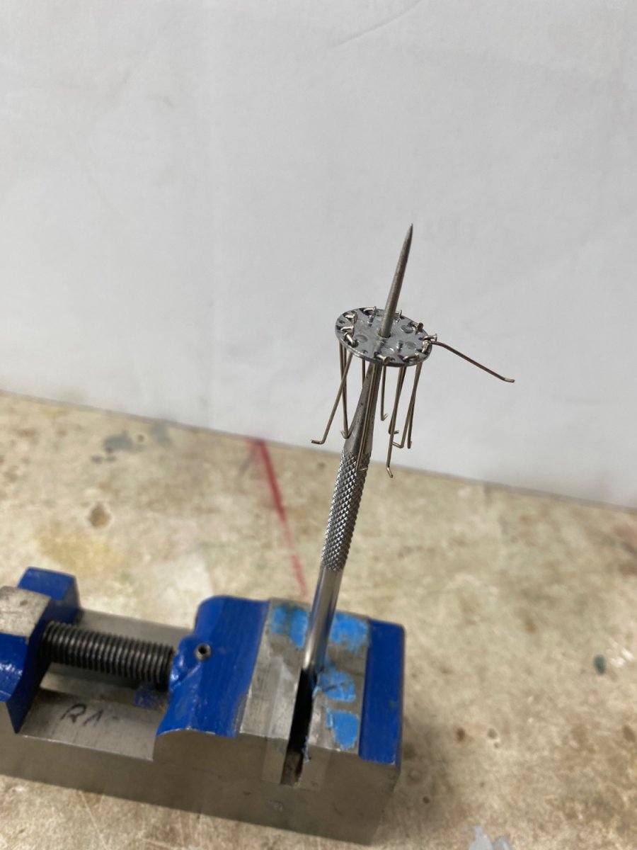
This was a little complicated as the spokes are feed alternately on the hub holes: half up and half down. Then another crisis developed. The instructions indicated that the spokes would be lined up as per the diagram and then placed on the corresponding slots in the rims (#47 and #48 below).
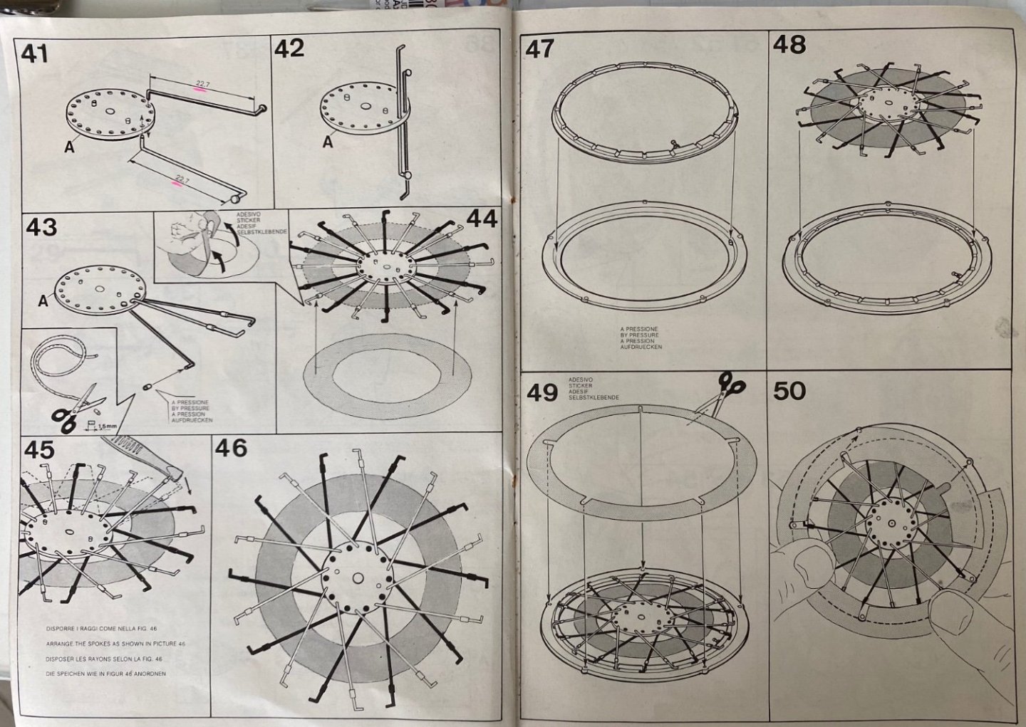
A tape, with adhesive in one side, was provided to spread and hold the spokes (see #44 and #46 above), but the pattern in #46 is not to scale and therefore useless. I scratched my head several times and decided that I needed something to hold each spoke in its slot (unglued) while I located the others and placed them in the rim. The answer was using modeling clay to hold each spoke in place. Success🙂
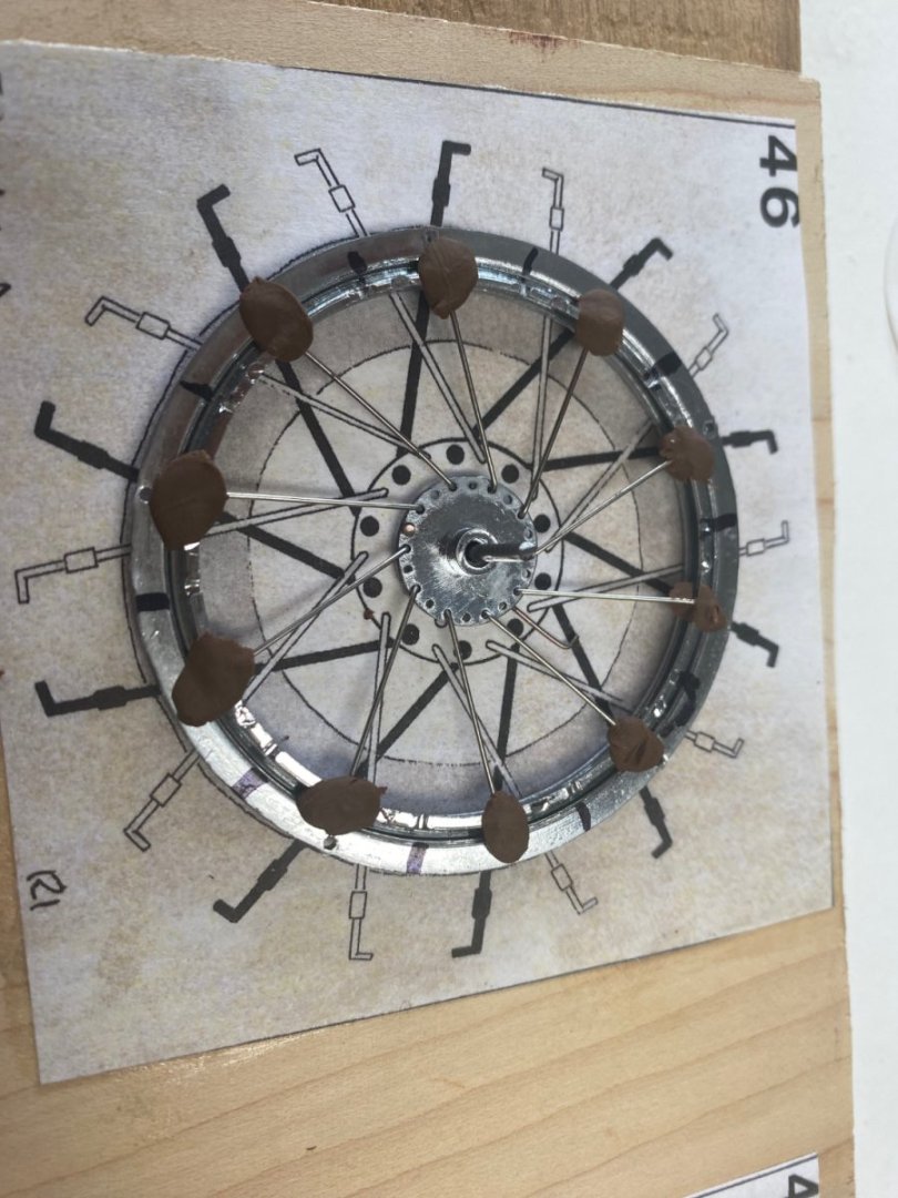
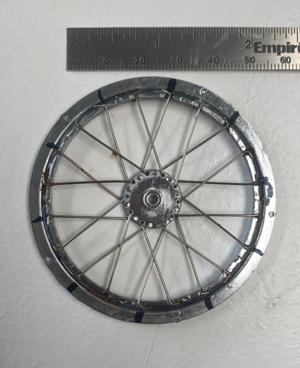
And here are the results.
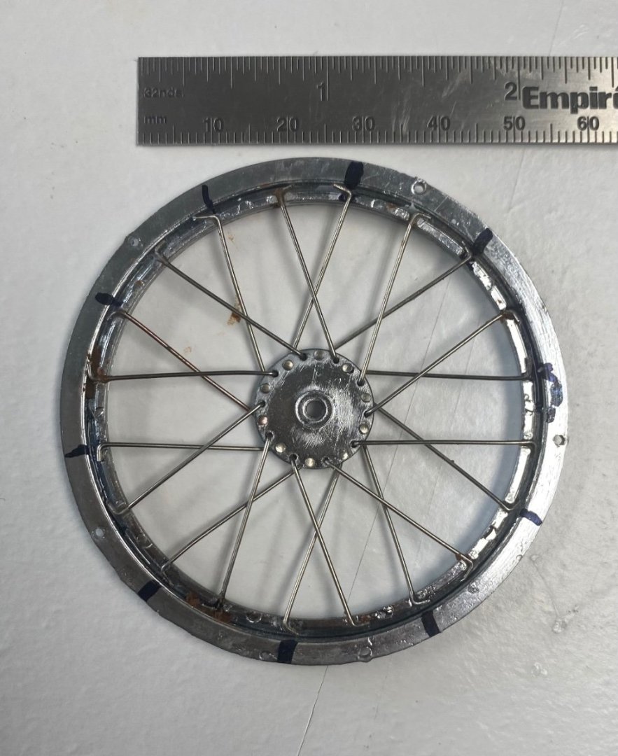
And, to make it more interesting, I assembled the second half of the rim's hub backwards. I had to submerge the rim with the spokes in acetone to remove the CA glue. But there is a happy ending to the story.
The challenge continues........
-
Now you got me excited. I will be following you. I thought that my Bianchi was complicated. Your engine is a beauty. Kudos
- Jack12477, Egilman, Old Collingwood and 2 others
-
5
-
Did the negative wash of light over dark and following are the comparisons.
Before:
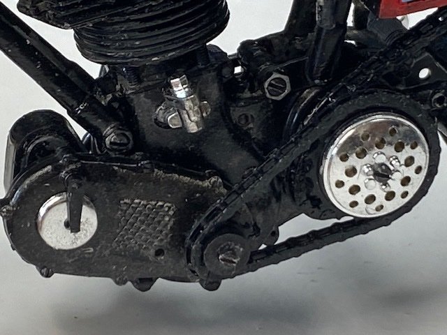
And after
I used Vallejo grey and silver. The result looks like a dirty engine and the black hole of gloss black is gone. Following is the progress to date:
Spoke wheels next.

-
Thanks for the comments and likes. I went to CDW's log of the Buccaneer and got very good tips about washes. BTW, he's done a beautiful job on that aircraft. I am going to paint some plastic with the gloss and try a negative washing of light over dark. I will follow up with my findings.


African Queen by gjdale (Grant) - Billing Boats (modified) - Scale 1:12 - RADIO - Live Steam
in - Kit build logs for subjects built from 1901 - Present Day
Posted
Sorry I couldn’t be of more help to you on the African Queen model. I built mine many years ago before I joined this forum. I remember it was a fairly easy build until I tried to run it on steam. The little oscillating steam engine wouldn’t move the boat at all. So the I cheated by disconnecting the steam engine and adding an electric motor. The boat then ran perfectly. I could fire the boiler and get the steam going while the electric motor did the work. Very satisfying
experience..Good luck on your build.