
HOLIDAY DONATION DRIVE - SUPPORT MSW - DO YOUR PART TO KEEP THIS GREAT FORUM GOING!
×


Kevin-the-lubber
-
Posts
1,230 -
Joined
-
Last visited
Content Type
Profiles
Forums
Gallery
Events
Everything posted by Kevin-the-lubber
-
 Bill, to add a useless comment (I'm full of these), you probably wouldn't have been able to get such a nice craqueleur if you'd tried 🙄. Commiserations my friend, it does seem like this model is often two steps forward, one step back..... and sometimes the reverse.
 -
For me it was almost the exact opposite. I did an apprenticeship and spent the next 10 years being paid a pittance as a sheetmetalworker/welder, realising I had already reached the ceiling, pay-wise, by the age of 30. CNC had come into play by then and, while I could see that it was going to take all the fun out of the job, I found it interesting, especially the programming. I left the trade not long after but still draw on the skills, always have done, but had I remained I’d have wanted to get into CAD as I much preferred designing (problem solving) than making! I guess for me F360 + resin printing is a marriage made in heaven.
- 536 replies
-
- 4
-

-
- Quadrireme
- radio
- (and 1 more)
-
Just bear in mind that I'm not speaking from experience here - I haven't painted these yet and do expect that to be 'interesting', as they say.
-
This is only a personal view but so long as the stripes follow a natural line, have crisp edges and are reasonably close to the real thing, who'll notice? I doubt the Heller lines are that precise. I guess it's all down to what you're after, true to the real thing or a good representation. I abandoned the former ages ago. You're making huge progress here Bill, at this rate you'll be rigging within the month.
-
I doubt you'll be far out anywhere Bill, nothing that you can't straighten out with the black by eyeing up when you tape it up for that.
-
F360 - yes, quite a learning curve and, in my case anyway, sometimes very frustrating. And to be honest, I think this project is probably towards the higher end of using it. Tinkercad is really quite good for a lot of stuff but not something this complex.
- 536 replies
-
- 1
-
-
- Quadrireme
- radio
- (and 1 more)
-
I didn't know that, Daniel. I think I'll keep mine transparent as for mine it makes no difference either way. You did some amazingly sharp painting there, those corbels are very difficult even to model. Bill, the top row is glazed, that was my 'I just want to paint something!' moment a few weeks back but it's not the finished article. I resin printed the panes for that one but the finish on one side of the 'glass' is pearl, which is why you can't see through it. I'm still undecided whether to take the easy route and stick with that method or treat myself to an expensive gateau and use the clear plastic it comes in for window glass.
-
Thanks, it's coming along bit by bit. That one was the first 'print & paint' to see whether this was going to work out as hoped for. I'd guess at another month or two till I have a complete replacement stern and quarter galleries. This is why I'm starting to notice various small details, as I'm staring at the one area far too much!
-
This is what I mean Bill. It'll be clearer when you offer up the large stern piece to the assembled hulls.
-
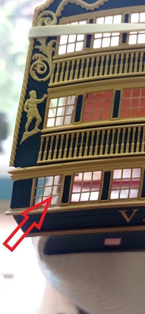
Yes, I have, same with those on the counter. I forced a scalpel through bit by bit, wiggling it around, after shaping a bit of wood to go underneath to give support while I cut through. I could probably re-use the doors with a little dressing. Something I noticed today which you might want to think about. Where the hull butts up to the stern plate, it misaligns to the line of the windows. This is because the window edge line is straight all the way from top to bottom whereas the hull curves gently outwards from top to bottom. Consequently, the hull interferes with the bottom outer windows by about 1.5mm. Easy fix is to sand off the wale in the quarter gallery area, that’ll be enough and it’s hidden anyway.
-
By the way, have you also got/looked at 'The 100-Gun Ship: Victory' by John McKay. It also has excellent drawings of blocks and rigging. I have no idea how accurate it is or how it dovetails with Longridge but personally I'll be slightly more inclined to start with this as the illustrations seem very clear.
-
I’m sure it’ll all be fine Bill. If it was me, I’d just be careful about the faint bee lines that give a guide for the yellow and black stripes.
-
The side entrance is next on my list. Daniel does a very nice kit including steps. For me it was a must do, not just because it adds detail and colour to the sides, but because the moulded steps are a bit bland. I've had a couple of goes at it myself, first making steps from evergreen card - they were pretty rubbish - and then 3D printing on a filament printer. https://modelshipworld.com/topic/23247-hms-victory-by-kevin-the-lubber-heller-1100-plastic-a-novices-journey/. Better, but I'm still not happy enough with the result and, as the kit in my log is just the practice kit for trying stuff out, I'll be using a slightly approach when I go back to it, and resin printing which allows 100 times the detail, literally I think.
-
Hi Bill, I haven’t opened this one up yet, but probably will once I’ve finished remaking the quarter galleries and was thinking I’d ignore the moulding and align it to the ones above. I don’t know how worthwhile it is, as my current ‘design intent’ has me resin printing the window panes and it might be literally invisible. But if I use clear plastic (likely) it would be. I have opened the closed ports at the prow and stern, just because I want as much detail as possible. Personally I doubt I’ll widen the wales and especially not take off the grain! Much as I’d like to do both and think them great modifications, I think I’d lose the will to live or at least to keep working on the model! Famous last words though, it wouldn’t be the first thing on the model where I’ve done a complete rethink and gone back to the beginning.
-
He can always hold the door closed with his foot, Daniel :-). Or whistle. When you did this, did you recut it to align with the other doors? It has the strangest angle.
-
The odd thing is that yellow ochre is the only one, so far, that gives me trouble and does so with every bottle - I have wasted a lot of paint through trying to clear blockages and now have a lifetimes supply as I figured I might go through tons of the stuff by the time I've got everything done. The others that I've tried go on beautifully.
- 2,696 replies
-
- 3
-
-
- heller
- soleil royal
- (and 9 more)
-
We crossed in the post! Thanks, I'll certainly try this. Your comments about the vallejo yellow ochre are interesting. I'm using the same for the victory though the airbrush version (model air), which I imagine is still basically the same. To be honest I use it because I needed some practice paints to learn airbrushing and bought one of their sets, but as it happens I like the tone a lot so if possible will stick with it. However, it clogs the airbrush in no time at all, quicker than it takes for me to spray half a dozen pieces like my window frames and balustrades. I wonder if that's the sediment. When I do my next batch of test prints I'll be trying retarder, as it dries so quick - another possible reason - and thinning.
- 2,696 replies
-
- 3
-
-
- heller
- soleil royal
- (and 9 more)
-
As you'll have gathered, I'm in no hurry, so whenever you have a spare moment or need a break from the eye strain.
- 2,696 replies
-
- 3
-
-
- heller
- soleil royal
- (and 9 more)
-
Just exquisite. I'm sure that like all artists you only see flaws but what I see is as near to perfection as it gets. One acid test for me is whether the 'picture' draws me in, do I find myself constantly looking deeper and deeper and seeing new, delightful detail. Or do I just think 'that's nice' and move on. This is very much the former. I'm really interested in the ink wash. I barely know how to paint models yet, compared to the rest of you, but do know I want my Vic colours to have this same, slightly subdued look and to enhance the depth of detail. If you've described this elsewhere in the log please just say so (I'm such a lazy reader sometimes) but otherwise, how did you settle on walnut, do you dilute it or is it straight out of the bottle, do you apply very selectively or just do a wash over the whole section...
- 2,696 replies
-
- 2
-
-
- heller
- soleil royal
- (and 9 more)
-
Bill, as by now you’ve probably discovered, when you dry fit all the decks one or two of them tend to fall off their perch as some of the beams only just catch their locating lugs in the dry. Especially when you fiddle in the top deck. I guess this is down to slight distortion of the hull after ejection from the moulds. I temporarily extended the lugs and reinforced the beams a bit. I don’t know how to cross-reference on here but it’s shown on my log. Not tidy as it’s all temporary but it helps.
-
Bill, this is what Daniel probably referred to: https://www.scalemates.com/kits/krick-82001-bruenierungsmittel-50-ml--1221525. whether you can get it in the states I don't know.
-
That should keep you busy for a while🙂. Are you going the whole hog, replacing all the rigols, doing a side entrance etc?
-
Same here. I was absolutely despondent when I picked up the model again after several years break to find Pete Coleman’s site gone, but then thankfully found MSW. I could spend a fortune on models after grazing around the logs on here.
-
That's interesting, I'll keep that in mind. I think it would be difficult if I go down the tiffany foil route, but straightforward if just painting and I haven't decided yet - probably try both as I have two kits. I've just had a quick play with evergreen and see what you mean, it's like a hard soap, isn't it, very amenable. It had never occurred to me to sculpt it and I imagine it lends itself to heat forming as well.