


Kevin-the-lubber
-
Posts
1,232 -
Joined
-
Last visited
Content Type
Profiles
Forums
Gallery
Events
Everything posted by Kevin-the-lubber
-

3d printing process
Kevin-the-lubber replied to henrythestaffy's topic in 3D-Printing and Laser-Cutting.
I haven’t tried any colours at all, always gone grey as everyone says it’s the easiest for seeing the detail before painting. I was thinking of getting some brown for making blocks etc, but maybe black is worth a go. It certainly has a nice look to it. I’ve just begun a new run of printing and, oddly enough, the elegoo ABS-like is coming out a bit softer than previous batches. So I wonder if mixing resins was, after all, quite a good thing to do. I only did it because they were test prints and the end result didn’t matter, but I think I’ll try a standard and abs mix again shortly, and be more scientific this time. Out of interest, presumably you printed the cannons vertically, with supports on the muzzle? Any issues with that? I had planned on printing vertically with the muzzle flat on the plate, to avoid support dimples, but am conscious that there’s nowhere for the resin to drain from the barrel. -
All’s gone well this evening. I need to rethink using locating pins, at 0.8mm they are too hard to distinguish from supports. But I think I’ll have a lie in tomorrow! A master - nowhere near it I’m afraid, when you see the skills of the pro’s. I’m just becoming more and more stubborn with age 😀!
-
Thanks Marc. I'm not entirely there yet - the print currently underway is the acid test (the windows, figurine, scrolls), but if it all goes together as planned I'll have a very nice, happy and long sleep tonight.
-
I've used it extensively - bear in mind that thread is several years old.
-
Try this; https://forums.autodesk.com/t5/fusion-360-design-validate/how-to-draw-a-boat-hull/td-p/6428751. I always listen to what Peter Doering says, he knows his stuff. You'll find examples in the thread which might be useful - I haven't looked but some of the lofts on my stern follow the same principles. Personally I wouldn't go near forms for this, and I only use surfaces when lofting or sweeping aren't possible.
-
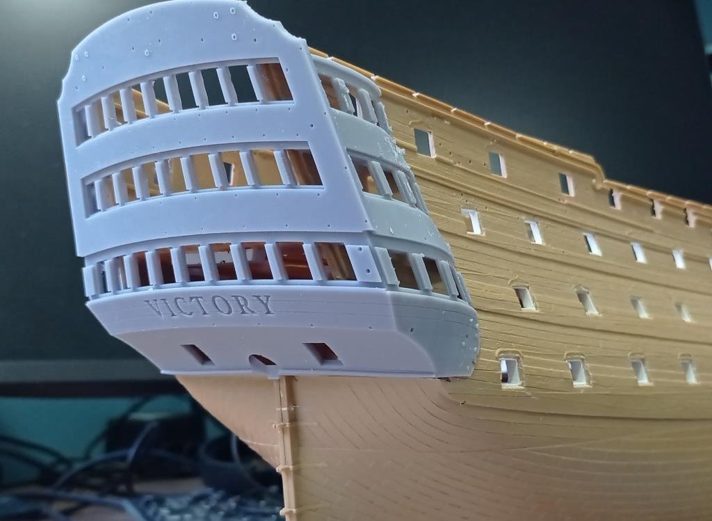
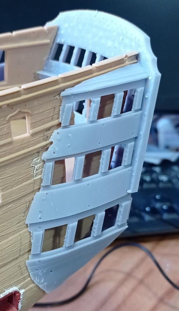
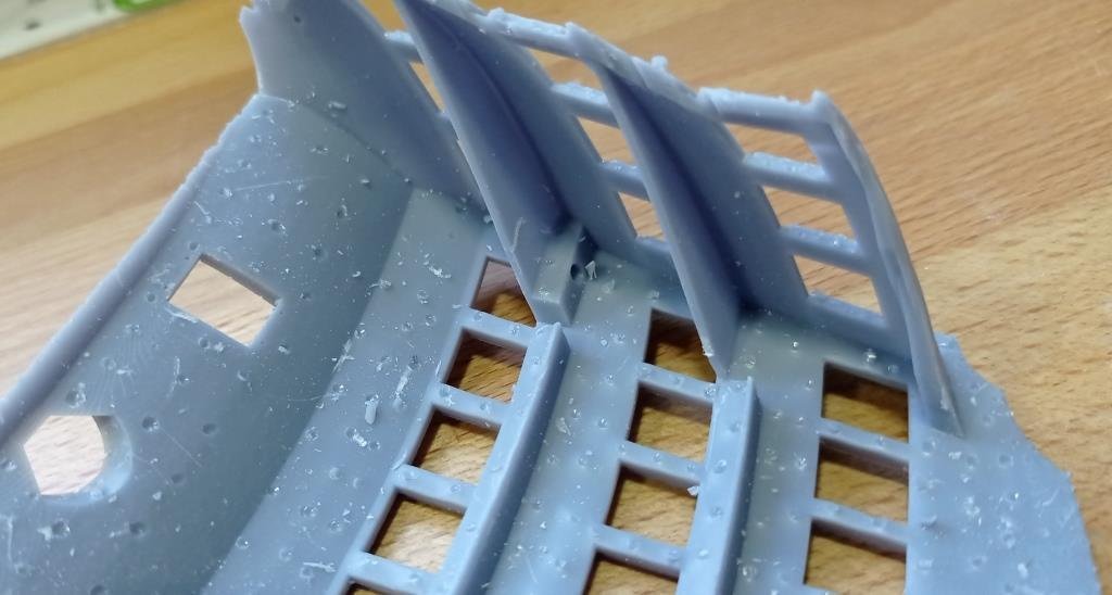
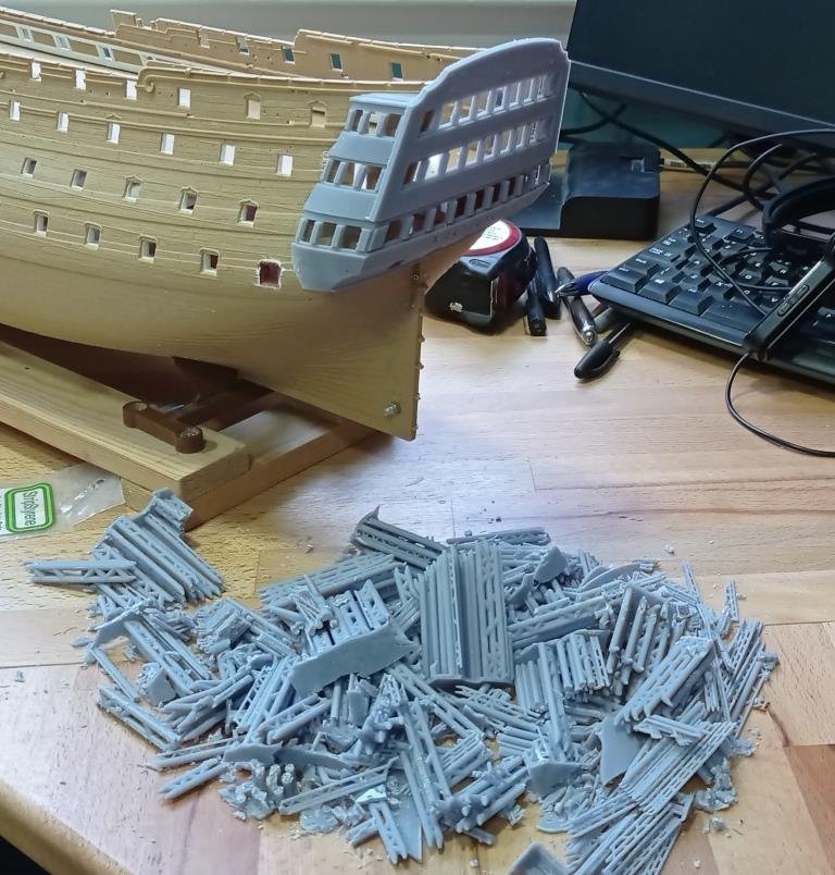
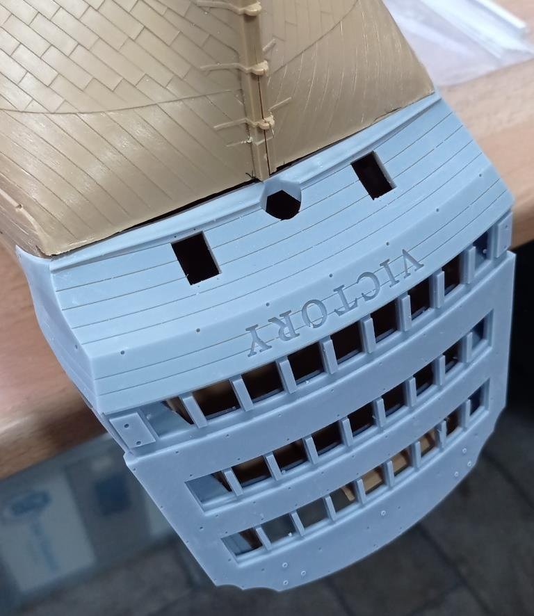
Probably the trickiest part to print, the main body.... Resin printing is fabulous for detail but, as with all things in life, you can't have everything. Hence the inside (second photo) looks like it's had the Intrepide or Redoutable lobbing 24 pounders down the length of every deck all day long. This is the underside when printing, to which all the supports attach. My priority is to try to keep the visible outside edges as sharp as possible, especially the very top and the letters, at the expense of the interior. This is a test fit directly after removing all the supports and before cleaning up. I've built in the benches in the captain and admiral's quarters, as well as the quarter gallery floors (with en suite's of course), to give added rigidity and assist with fitting. Between them, the benches and floors lightly pinch the hull sides such that the whole thing sits in place without glue. Though the lower floor needs moving up a foot or two, you'd be needing a ladder in real life. All that mess in the third picture is the printing supports. More resin goes into these than in the part itself, but I've learned to go big rather than penny pinch. I think somewhere in that pile is the lower gallery decor I made a couple of days ago 😂... I tested it for fit ( fits nicely) but can't find it now so assume I scooped it up when tidying up. The only area that will, I think, need more than the lightest filling will be where the lower counter meets the hull. It's as good a fit as the kit part, which isn't saying much! The gap won't be as big as the picture suggests, just a little where the hull halves don't quite match.

-
I just got a chance to try the same thing (projecting the curves) myself, today, as I haven't used the project>intersection function, but as you say, it doesn't do the same as the solidworks equivalent. Pity, there are places where this would be useful. I think the best way to do this in F360 is through lofting with guide rails. The workflow would look something like this; 1. Draw the half deck view. You will only really need the outside edge, as a lofting guide rail. 2. Draw the side view. for the sake of simplicity here, keep the top edge straight and horizontal. make sure the sketch is closed (extrudable) 3. Draw the half stern view. Again, for simplicity's sake, make the top edge horizontal. (make sure the sketch is closed (extrudable) 4. loft the end to the side using the deck edge as a guide rail. This will give you a solid half. You could just as easily offset the hull edges to give a thickness and loft these. For what it's worth, I sometimes get tied in knots when lofting, with profiles apparently intersecting etc. And in passing, I sometimes get problems when combining complex shapes; I mention this because I use the same solution for both - I move one adjoining line either back from (lofting), or further into (combining) the other by typically 0.01mm. This usually does the trick. This issue has been very common, for me, when doing a '90 degree' type loft where the sections have a common line.
-
Thanks Marc, the hilarious thing is that this all started out as a way to have a break from my unsatisfactory and frustrating efforts to model the side steps - I thought I'd spend a week painting the stern from the kit, which looked interesting, while awaiting inspiration for a better way to do the steps. Until I found it impossible to paint the balustrades.... 😃. You'd have just got on with it! But it's got me to learn basic 3D modelling and the side steps should be much easier to get right, now. I know I can still improve on some bits of the stern, I could probably easily 'etch' this part a little more for instance, but at least I now have a fair base to work from if I get the inclination and, once I get the printing setups right, it's easy to make changes. I still haven't got a trophy that I'm happy with but will leave that for another day, nor touched the lanterns, which don't look so hard.
-
Half of this conversation sounds like etruscan to me.... jeers, thimbles, futtocks.. Which probably gives you an indication of how I'm getting on with Longridge, Bill. I like the drawings though. Look, it's simple. You just send it to me when ready, I'll stick it in my garage, after a month the resident spiders will have it covered in silken strings so fine and taut you'll be the envy of the entire forum.
-
It does hint at those round inflatable lifeboats on modern ships... does it have a quick release mechanism somewhere😊? In any case, plenty to hang onto once in the water....
-
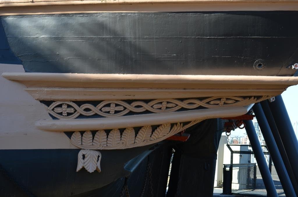
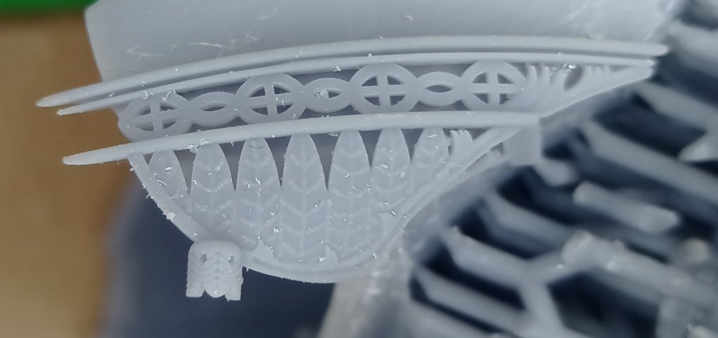
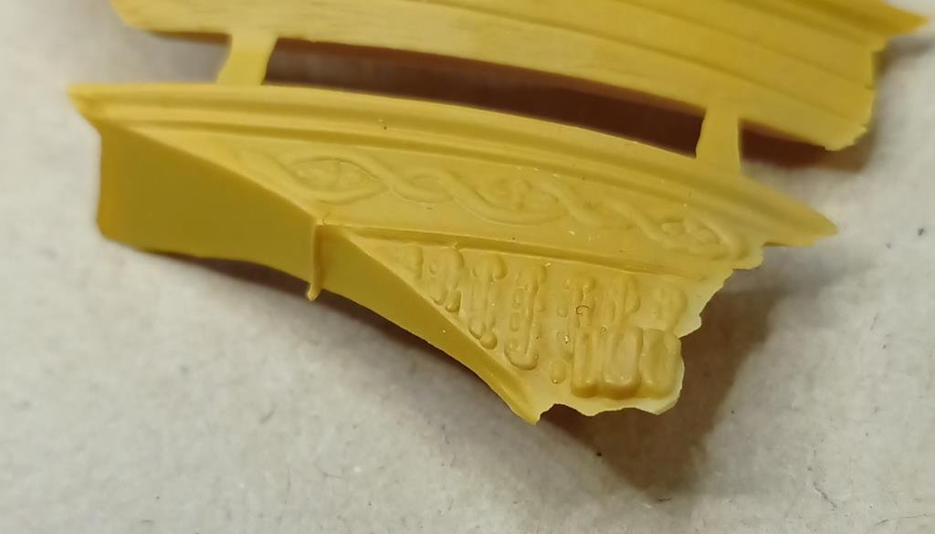
Big day for me.... I essentially finished the stern modelling today, at least as far as I'll go with it for now. I have a printing marathon ahead... there are 39 parts to this 'mini-kit' and each one requires a lot of patience to set up for a good print, and no doubt some things will need a little fiddling. Here's the first off the press today, the fine decor at the bottom of the quarter galleries and lower counter, in this instance resting on the dummy body I made a couple of months back. Far from being an exact replica but I think it'll do. It's also the first time I've managed to do something using meshmixer, which I used to add the lines on the leaves.
-
Ah, now it makes sense. I knew there would be a good reason for it. Wow, that's a big platform, roomier than I thought. Sadly no longer present on VoP.
-
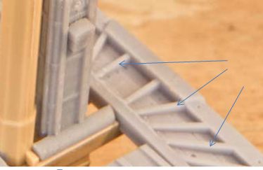
Neither, I mean the infill battens (or whatever they would be called) arrowed below. These days I imagine they'd be called a trip hazard :-). I realise these platforms were not for the faint-hearted and tripping was probably the least of your worries when someone was blasting cannonballs at the lower mast, but there must have been a reason they weren't just planked on top to create a flat working surface? (Meanwhile, I'm eyeing up the carbon fibre rods on my daughters old kite and thinking, would she ever miss it..... would she ever know.....)
-
On a different note, one of idle curiosity. Do you know why the fighting tops had the planking underneath the ‘joists’? I’m sure there was a good, logical reason for that.
-
I’m sure you would do this anyway but it’s worth mentioning at least two things here for beginners (I of course learned the hard way!). - make sure, when you create these planes, that the hull component is active (radio button checked), not the root. Otherwise It is an utter pain, down the line, to be trying to remember where things are. - name each plane, much as you do in solid works. Same reason - in a months time ‘Plane 3’ will mean nothing to you. I now name absolutely everything - every plane, sketch, extrusion, cut, etc etc. It takes very little time doing this as you go along and you get payback later on as it’s now very, very easy to isolate particular sequences in the timeline.
-
There's truth in that. Regarding resin, I'm finding ABS-like resin fairly tolerant of flexing, up to a point; and at that point, it simply snaps rather than remains bent. I keep meaning to read up on the structure of cured resin, I imagine it's crystalline, in case it's possible to heat treat it post-printing to make it more fibrous. I would have thought that, if the mast or spar has a carbon fibre/steel core, it would be fine. Something I'll test at some point.
-
Lovely detail there Daniel, even with resin printing (I assume) it looks like you are pushing the boundaries. I especially like the plank lines on the underside of the top. I have to admit I probably wouldn't have even thought of that. Are you not tempted to remake the masts as well? Doesn't look that hard 😁.
-
EG, this is a very helpful tutorial around basic workflow alone, I’m already beginning to feel slightly less daunted by the idea of taking on a hull (I.e a whole scratch built 3D printed mode). Richard, such a shame your couldn’t get permission for an AOTS book for the Cutty Sark. It’ll be the next thing I’ll build. I’m sure many here would appreciate a topic on building it in CAD.
-
That narrows it down by one, I'll pass on Rhino then. I'm sure NURBS and all that is absolutely riveting to study but I just want my stuff to print, and now (goddammit!). What a rabbit hole, eh! As I've mentioned on one of our other threads I get massively frustrated trying to manipulate edges, points and faces using forms for sculpting, I just want to 'draw' grooves, bumps, ridges etc and have the software do all the thinking and, preferably, read my mind and help me out a bit :-).
-
Thanks EG, that makes me think it is probably worth at least taking a look at Rhino and Solidworks. This appeals "free-form 3D modeling tools .... Model any shape you can imagine" as I'd like to be able to sculpt directly in the programme but still struggle with forms in F360. Rhino has a 90 day trial period, which is long enough to try it properly, and the student licence is a one time payment of about $200 (my daughter is still at college). Solidworks comes out more expensive at $100 a year for students, which is still tolerable-ish, but only has a one month trial which for me is a little tight. To be honest I don't understand the solid modelling vs non-solid modelling difference. In so far that I don't understand what else you have to do with Rhino in order to 3D print the bodies. I see printed models on the web developed using Rhino - presumably you have to do something or use another programme to convert the (mesh?) into a solid? Does this make a difference, do you lose fidelity? Or be forever fighting non-manifold issues?
-
Chair pulled up here too ... I'm particularly interested in how you think the different software packages compare (in terms of executing the tasks). I've invested hundreds of hours into learning just enough F360 to be a danger to myself and, while that time investment makes me loathe to change horses, I do have it in mind to try one or two of the others presently, for the reason below. Though mostly I'd love someone to say, this package is best for this game, forget the rest! To state the obvious, ship modelling is inherently "curvy", meaning there are lots of bodies with complex curved shapes and F360 can become very, very slow to compute once there are a few of these in a project. Although I say I have spent hundreds of hours learning, it's probably more true to say I have spent 60% - 70% of the time swearing at the computer while watching F360 grind through the computations, including times when, after 5 or 10 minutes of frozen cogitation, it says 'no can do' (and breaks a few actions further back in the sequence). Consequently a lot of my more recent learning has been about the dark art of workarounds i.e. optimal workflow. This aspect is not always obvious or intuitive. Imagine a simple cube, for instance. There are umpteen ways of making that in F360: simple extrude, sweep, loft, form, surfacing, ruled, thicken etc. When the shape is complex, some work better than others, in fact some will work when others, inexplicably (since the end result would be identical) won't. I think F360 is still a little buggy... but it's free, so I shouldn't complain too much. And to be fair, I sometimes see tutorials by experts who absolutely breeze through creating a complex body in 15 minutes that would take me a day and use functions/workflows that I wasn't even aware were possible. So it's probably also just me and sublime ignorance. In answer to a query on the F360 community forum, a yacht builder sent me this, which might be of interest; Another piece of free software that I use a lot is this one: https://www.polycad.co.uk/ It's tailored for boats, but I think it has some really cool 2d and 3d tools for surfacing, especially the ability to switch a surface from a mesh to a nurbs, or something like that! I had a brief look, but it looked a bit complicated!
-
3d printing process
Kevin-the-lubber replied to henrythestaffy's topic in 3D-Printing and Laser-Cutting.
I only used one bottle of water-washable and have a feeling I mixed half of it with standard resin to use it up. I think I just found that the surface finish seemed fractionally less sharp. I also wasn’t too keen on washing prints in the kitchen sink, I really don’t want a blocked drain down the line. I find FEP gets dimples from supports and this makes fails a little more likely. I had a terrible problem with supports breaking halfway through a print until I was told that extending the exposure time was the cause; reverting to recommended settings, and beefing up the supports, sorted that out. But I agree, more and stronger supports is safer. Same wrt paper towels, though to be honest, I haven’t found hazy FEP making any difference. -
The worst of it is that between you, you have got me thinking all the wrong thoughts. It probably isn't nearly as difficult as I'm making out and it's oh so tempting to just play a little. Especially as I've just received a very large wash'n'cure machine which seems to be begging for particularly large prints. A thought that keeps recurring, as a way around the size limitations of hobby printers, is a plank on frame approach. Imagine: a resin printed frame, to avoid what looks like the hard parts of that (not that I've ever made a plank on frame), the getting it absolutely true and absolutely accurate to the 'drawings'. Then 'plank' it with sections of faux planking, but with the plank sections keyed into the frame so no creep through fractional cumulative error. No bending to shape, no cutting, able to design in all the detail (admirals entrance, proper side steps, rigols, wales, thickened gunports, internal framework, no woodgrain).... The big question is whether the resulting model would have any soul. I'm reminded of the anecdote about the very best handmade persian rugs, that they always contain one tiny, deliberate mistake, because that virtually undetectable 'error' is what brings them to life. Whether this is a true story or not, I agree with the sentiment - machine made art is rarely quite as beautiful as that made by hand. Anyway, I will at least concentrate on finishing work in hand first, and on getting to a stage where I can finally make some progress with the kit hull.


