
HOLIDAY DONATION DRIVE - SUPPORT MSW - DO YOUR PART TO KEEP THIS GREAT FORUM GOING!
×


Kevin-the-lubber
-
Posts
1,230 -
Joined
-
Last visited
Content Type
Profiles
Forums
Gallery
Events
Everything posted by Kevin-the-lubber
-
 Raise the waterline? I haven’t spotted that one in my reading of build logs so far, could you tell me more? Once I’ve got the stern more or less finished I plan to go back to the admirals entrance and side steps - I’m not happy enough with my first attempt (which was probably more like my 3rd or 4th) - and know that the lowest step was right at the bottom of the wale. Or is it just a question of moving the paintwork a little higher? The stern of the SR would be massively challenging in CAD. Not the basic structure, nor the more geometric mouldings, if you know what I mean, but all of those ‘not a straight line in sight’ details. At some point I have to learn one of the sculpting packages, I’m putting it off until I have no option because initial attempts have been frustrating, but I kind of know that, if I achieve the standard I’m aiming at for the stern and side entrance, I’ll inevitably want to work on the figurehead. I haven’t read enough of your log yet to understand what material you use when your sculpting, is it putty or plastic or wood? Because, despite favouring CAD and resin printing (for ease of modification) I can foresee that there are points where it would be more sensible to create by hand.
 -
Ditto. One of the challenges of the Victory is that, with a site like this available, it’s like having a 1000 page instruction manual including several alternative ways of doing many sections. Make that 5000 pages. Not that I’m complaining, it would be virtually impossible without the build logs and advice. So I am gradually revisiting logs, like yours, and really appreciating the artistry that’s gone into the build.
-
The connections in life are often interesting. I finally got my head around Fusion 360 (CAD software) through reading a tutorial in an Australian magazine called Diyode. The title is a play on words, the mag is aimed at electronics hobbyists with a heavy focus on arduino. I know absolutely nothing about electronics or arduino’s, the former especially is a dark art to me, but some of the little projects they describe piqued my interest and one day I may try getting over my mental block with things electronic. Now, this project sounds REALLY interesting Ian. Even as a dry land model imagine how fun it would be to, on the hour, have the oars slowly do a synchronised, Mexican wave type rotation🤪. Extrapolate further - the victory’s gunports open and the guns roll out one by one. Incidentally, this is where 3D becomes really useful - you can design all the parts and then have the movement simulated before you commit to anything.
- 536 replies
-
- 2
-

-
- Quadrireme
- radio
- (and 1 more)
-
Note to self - do your homework better next time. Now that I look back through my chaotically filed photos I see it's present on loads of them, just looks like caulking. And, strangely, that small piece of architrave does just end where it ends. Strange. I'm not quite sure where to go with this now. I like the idea of running the side gallery completely flush with the rudder plate but don't like the way this ends at all.
-
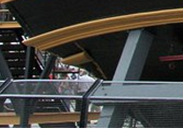
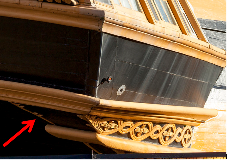
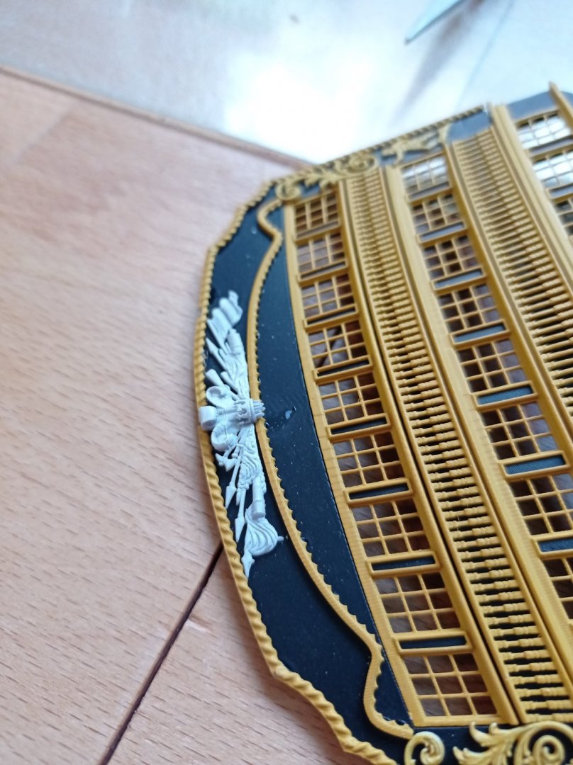
To digress slightly; Here’s a little detail that’s aroused my curiosity. When I first noticed this in photos, it just appeared as a thin line at the bottom of stern photos and I assumed it was some caulking done during the current restoration programme, awaiting painting. But when I enlarged this photo to get a better look at the pretty decorations at the bottom of the side galleries, I noticed those small, regular ‘cusps’ on the line, and coupled with the colour in this photo – ochre – this detail now looks more like decoration. This is absent on Heller and I don’t think I’ve seen it on other models; nor is it present in any other photos in my web collection, though that may be down to the angle of the photo. Or it could have been removed during restoration as there is so much wood-rot in the stern, and been subsequently put back. This is an area of the stern where I am struggling to find, via the web, any photos that clearly show how this lower-most section of the side gallery knits into the stern plate. Heller seems to have the rear edge of the small piece of the side galleries sitting very slightly back /offset from what I call the rudder plate i.e. it protrudes from the side of the hull rather than sitting flush with the rudder plate. That would make sense of this detail, which would then sit in a corner. Likewise the short return of the architrave, which would otherwise end in space, whereas an indented bottom would have it ending in a corner. At the moment, my plan is to indent just a little and try to incorporate that corner detail, though it’s so small it may not be very practical. Or maybe better done with a little bit of evergreen down the line. I’d certainly welcome any better shots of this area though. And this photo is just one that made me smile. I’m in the middle of many hours of modelling the side gallery to the stern plate, mostly getting the compound joints of the rails to align. This is quite tricky given there’s barely a flat surface to work from, the rails have to twist along their length, etc etc. There’s a lot of trimming and lengthening involved: I move a rail a fraction of a millimetre, I then have to adjust the width of the stern, the angle of the compound joint (which of course then goes out of alignment) the cut from side to stern and so on. I chuckled therefore when I saw that the original builders struggled with the same issues and, it appears settled for a very slight bodge, as this is true for both side galleries.
-
Marc, I should have added, I am not even dreaming of your standard on the Soleil Royale. That is truly extraordinary - what I'm doing is just the application of my old trade skills and a growing knowledge of CAD, anyone could do this if they really wanted to. And by comparison, the Victory looks like a beginners model (which of course I am!). I don't know yet whether you've put me off trying the SR for life or made me want to have a go even more - I so love all the impeccable detail, the texture, the colours. Thankfully though, right now I don't have nearly enough skill to even dip my toe in the water of that pond.
-
I have that too but am a lazy student and more often than not discover key info after the event, at which point it makes sense.
-
That’s a lot of progress in a month Bill, and you’ve done well to get through those very repetitive jobs so soon. Every time I wander off into reading other build logs I discover loads of materials and methods that I know nothing about. Latterly, Marc’s extraordinary Soleil Royale and Doris’s Royal Katherine.
-
Thank you - every time I visit it, I marvel that I still haven't yet, in a fit of pique, set fire to the computer. I enjoy the learning, keeps the old grey matter busy.
-
We’re on more or less the same retirement trajectory. Feb 25 for me, all going well. With a bit of luck I should be just starting work on the lower deck by then🥵. Be warned, because so much is possible it’s an absolute rabbit hole. I initially thought this would be quicker and better than making things by hand from styrene. It’s clearly better, but definitely not quicker!
-
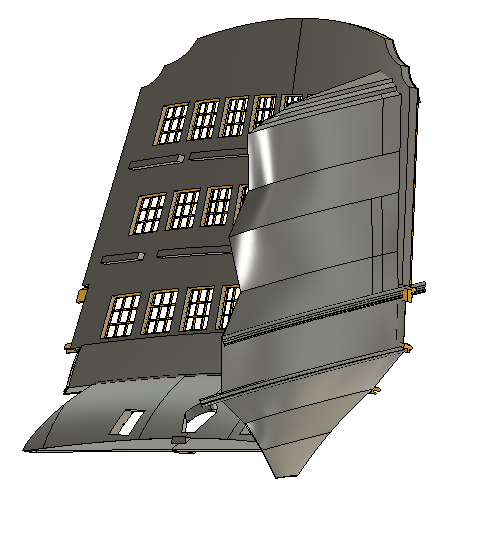
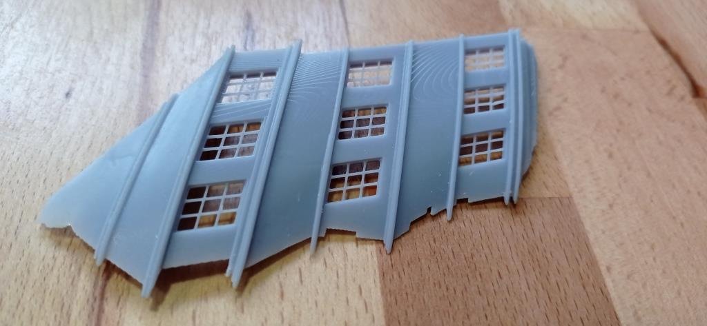
I didn't manage to make the trip to V@P as planned last week, hopefully some time over the summer. Meanwhile, work on the side galleries progresses. Devilishly tricky and time-consuming. I'm making a few changes from the stock version; all one piece rather than two (though the final version will still be in kit form), lower windows narrower, and when I get to it, I'll try to model in the floors and loos in situ as these should help for precise fitting; and I'll do one thing I've never understood Heller omitting - locating pins for the galleries to stern plate, or something that means it fits here and only here. The photo is a 'free-standing' version, just so I could get my head around it, understand what I was trying to do and what problems I'd need to overcome. It actually fits quite nicely! I'm now adapting all of that work across to the main file and, once I've got the panels and rails aligned, it'll be time to give it a whirl on the printer and start tweaking everything for a decent fit. Oh, and then no doubt spend many, many hours on the scrollwork and balustrades. If I don't surface again within a year, please send out a search party in a small boat, I may have fallen overboard. Incidentally, there's an artifact of resin printing which shows up well in the photo - you can get a lovely woodgrain effect for exactly the same reason you get it on real wood, the build up of tiny layers. Works best on curved and irregular surfaces. It's very subtle and completely out of scale but I think I'll keep as I like it, makes the parts look less plastic. Back to work...
-
It was also because I made a little styrene jig for glueing the carriages together - I make jigs for everything - and, as I glued away the jig got softened by the tiny bits of excess glue, allowing movement of the sides. Although this was quite a while back I think I thought the camber was by design and carried on. It was a good learning experience and, luckily, one learned on parts I can easily remake. Not just how easily the glue melts styrene but also how little is still more than is needed. Going down the 3D printing route has been a game changer for me. There are now very few parts that I’m fearful of irretrievably messing up through inexperience, probably just the hull and figurehead, everything else looks quite model-able. And I do expect to still learn many things the hard way, which is fine.
-
Bill, my error was putting a little camber on the vertical, what you’ve done is correct. That’s some nice detailing on the constitution - I have some ideas along those lines for my victory but don’t expect to explore these for quite a few months yet, if then. Too tied up with the stern section at present!
-
Indeed, and there are so many lovely little details that may prove hard to resist at least attempting. Something I’ve come to understand is that a build on this scale and at this level of detail isn’t really one model at all, is it - it’s dozens of models all brought together as one, some easy, some quite tricky and the end result will only be as good as the ‘worst-made’ part, up to a point. For me this is a useful perspective. Bill, I’ll be watching your build with interest. Although I technically started mine 8 or 9 years ago, in reality I only properly sank my teeth into this model last year so I’m not that far ahead of you.
-
That’s exactly where I began 8 or 9 years ago! But in my haste and ignorance I made a mistake, canting the carriage sides slightly inwards from the vertical. I only realised this was wrong when I visited the Victory not long afterwards. Not really a problem though as I’ll be replacing all of these with my own resin printed versions, when I get to it. As an engineering type my logic was that you’d need a little camber to make the carriage roll straight. (As if that mattered over that distance!). Currently I’m re-reading Daniels log again but more systematically this time, making notes of which ideas I want to incorporate and those I won’t or couldn’t. As I’m sure you already know, it’s a goldmine….. in every sense. Did any gold miner ever walk away saying, ‘I know there’s still millions of nuggets in there but I now have enough….’.
-
It does happen, Bill (he says wryly). Ambition outweighs talent and all that. Knowing about these forums is a mixed blessing. If The Heller instructions had been better I’d have probably finished my Victory within a few months and remained blissfully unaware of the various sites. However, as it would have almost certainly been of a very poor standard, by now it would have been landfill and that would have been me done and dusted with modelling. Instead of which, bemused by the poor destructions guide, I found Pete Coleman’s site and Daniels log in particular, and I’m still at it. As an aside, if someone had told me, at the beginning, that the kit itself was only going to represent a fraction of the end cost, I’d have thought twice. Although I would absolutely endorse any advice, to beginners, to start with something easier, I think the challenges would be the same regardless; if you want a really high quality end product you’re going to have to put in the hours, be very patient, and be very creative. I think too that if the base mouldings we’re not as good as they are, I might have quit altogether quite early on and, in that sense, Victory is not a bad place to start; you’re not fighting to make a silk purse from a sow’s ear, more trying to exploit the full potential of something already pretty good. I hope to one day move on to something like the Soliel Royale, but understand the quality is not nearly as good, so the Victory experience may prove useful.
-
Erik, that's exquisite. If you'd posted a picture of it bobbing on the waves I'd have assumed it was a freshly overhauled real thing. Even if I wasn't an engineer by training and nature, I wouldn't be able to walk past this without wanting to take it all in. Nail polish tips added to my ever-expanding bookmark list from this site!
- 222 replies
-
- 1
-
-
- First Build
- Lady Isabella
- (and 2 more)
-
Thanks Veszett, that's exactly the info I needed. Hopefully that spot is still accessible.
-
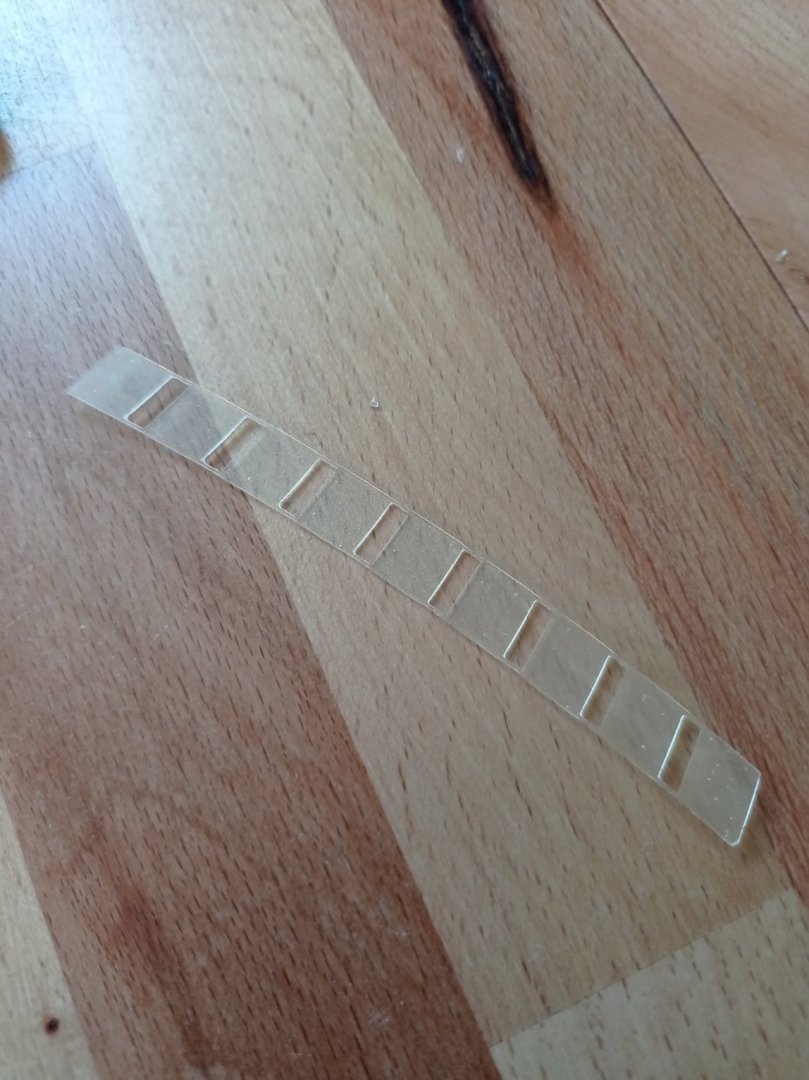
Glazing test, just the top row. First go with elegoo translucent resin. Not bad, not bad at all. Printed as a strip just to make it easier to know which pane is which, the tabs get snipped off for fitting. It has a slightly pearl finish on one side, glossy on the other. I believe it's possible to polish translucent objects for greater transparency, I guess the opacity comes from the pearly side. Though I could also just use it as a template for clear film. I haven't yet decided whether to furnish the cabins. It'd be so easy in 3D it would be a shame not to, but that's a decision for later on, and if I decide against, these will be fine just as they are. I'll be popping down to Portsmouth soon for a proper photo session, as it's only an hour or so away. If anyone reading has been there recently, do you know if it's possible to get a good, square on sight line of the stern from across the quay?
-
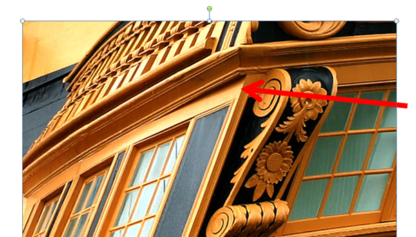
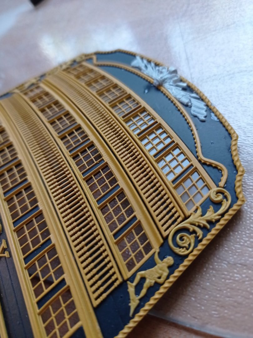
Hi Hubac, I love the rope in this form, in fact all the slightly thicker decoration. It gives more texture and relief, especially when viewed at an angle, and I'll definitely stick with this. Corbels - of course! I've been racking my brains for what these would be called, in the 3D file I've nicknamed them 'bumpers'! I do have them modelled but the filigree is so tiny and I haven't yet thought of a way to print it that wouldn't result in it breaking while taking it off the plate, or being virtually impossible to clean up. And a lesson learned on this model is that the smaller and finer the part, the more any mistake or cut corner will show up. You kind of picked it up through the question about the scrolls - I put them on wrong-handed, left should be on the right and vice versa, hence note to self to add pins. But you're right, currently they are every so slightly too wide but this is literally 10 minutes work to change. Imagine the heartsink if you'd made them from scratch out of styrene! I take my hat off to those on here who do that kind of stuff, it's way beyond my skills. Turgidity is good - as I'm sure you know, you can become so buried in the project that you get tunnel vision and need critical friends to tell you what you could do better. Figured out the lower window issue - it's not swollen, just too much paint. I can solve that with some modelling tweaks. I'm very inexperienced with an airbrush and have had a hellish time with vallejo model air yellow ochre, it clogs the airbrush within 15 or 30 seconds. Primer and black are fine, it's just the yellow, so if anyone has tips or suggestions please share. (Actually, just about everything on this model is a new experience!).
-
Thanks Ian, it'd be nice to recoup some of the cost - I don't even dare think in terms of time spent! Let's see how the side galleries go. You couldn't use this 'kit' with the stock sides as the lower window rails aren't true copies of the Heller, nor are they in the same position. That would have been way too hard (or too tedious) for me. But you're right, if it all comes out well it would make a lovely aftermarket kit.
-
or hours.... quick look at the trophy I made a few months back. Fits fairly well, will pull round to the curve of the 'teeth' decor, think I'll stick with this.
-
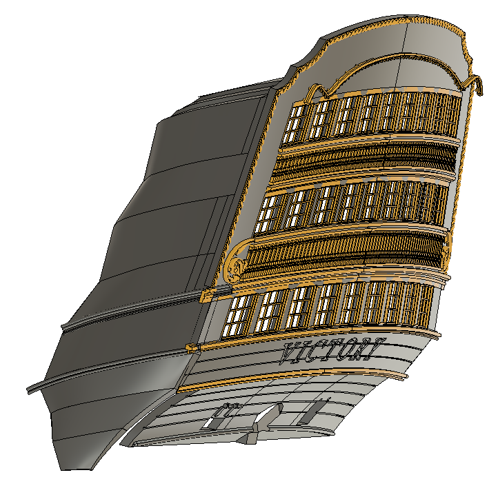
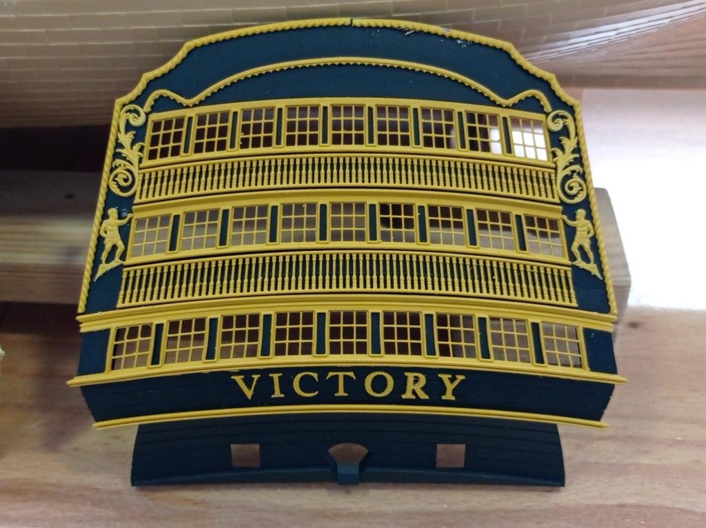
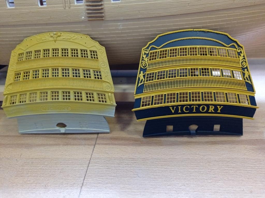
29/5/21 Closer… needed to take a break from staring at lines on a screen and see where it’s at in the flesh. I didn't bother cleaning up the parts hence plenty of artifacts, just printed, quick bit of airbrushing, stick it all together. It's not quite as good as I'd hoped for, 90%, but maybe I can squeeze another 5% through tweaking the design. This is officially MK2, in reality more like MK20 on the design side. I had to start again after the screenshots in the previous post, as my beginners Fusion 360 methodology first time round was dreadful and the file was becoming almost unusable. Certainly learned a lot about F360 along the way though. I still have some things that need work; the scrolls coming off the lower window balustrade, the bits either side of the lower window, the trophy, the glazing; if translucent resin works as hoped, a piece of cake, if not, I’ll probably try clear plastic film. I hope it’s the former as I have plans for the lanterns and skylight. Then the side galleries, which look like a 3D nightmare – plan A is to try re-creating the rear-most section of the hull in F360 so that, between that and the stern plate, I have datums. Plan B is not yet in existence. Plan C is Ebay and tending to my overgrown garden. May take a bit of a break or do some easy stuff like cannons in between times. No shortage of jobs on this project. The stern plate: ultimately had to split it into two parts as I couldn’t get a decent result printing as one piece. Need a bigger printer. You can just see the seam running across the lower balustrade, easy to blend it in when I go to final. Everything yellow apart from the scrolls and figures sits in grooves, for more ‘seamlessness’ and locatability. A prize to whoever spots the assembly error - (free advice to add locating pins on everything). Windows: obviously not a straight copy of Hellers, 0.3mm bars are much nicer (thank you for the inspiration Dafi) and I’ve opted for something midway between the plastic model and the real thing in terms of sills and framing. I’ve followed the broad dimensions and positioning of Heller, despite this being not very true to life. I’ve discovered a new problem after painting last night: the lower window seems to have swollen a fraction causing distortion when fitting -- seem to have broken a bar due to this, at 0.3mm x 0.5mm deep they break easily, expect less so once glazed. A tad more clearance should resolve that. Same with the letters – ‘R’ just wouldn’t sit in it’s recess. Same with the rope, LH side fine, RH side was too tight and I made a mess getting it back off for a quick trim, CA sets quick. Spoiled the black paintwork too, fiddling about. If the clearances are just right, things drop in as a snug fit with no touching up required afterwards. Balustrades: took more licence here as it would be impossible to see, with the naked eye, a recreation of the true carving on the rails; the scrollwork would be 0.1mm thick. So, basically square with chamfers and fillets. Good enough. Also shifted away from the dimensions of the model a bit, to suit the windows. The proportions of the windows and balustrades on the model are not that true to real thing, on which the rows of windows themselves are more or less equal in height, as are the balustrades. The sill work makes them look different heights. The assembly in the photos is still a proof of concept rather than the final cut and, once I’ve dealt with the side galleries, I’ll probably look again at whether the deck positions allow me to shift proportions closer to the reality. This is relatively easy in F360. That said, the decreasing height on the model is nice in it’s own way, plays to that architects trick for making things look taller and more grandiose, and the stern should be nothing if not grandiose. More in a few weeks, months, years!
-
Hi Helmut, I’m finding this to be the liveliest of the threads I follow, suggesting 3D is gaining popularity in this field as the equipment becomes so much more affordable. I think you’ll have fun with the Creality; I’ve mostly used mine for DIY projects or fun things.
-
Jerry, nice work. You must get lovely detail at that scale. I hadn’t heard of anim8or, any idea how it compares to other packages? I’m a day or two away from creating filigree for my 1:100 victory and, putting aside that I may need to learn and do it or finish it in blender, my F360 trials have been based on sweeping and lofting along traced paths. The ‘proof of concept’ tests have worked fine but I know I’m likely to end up spending countless hours at least on each little scroll, creating a series of profiles, so not ideal.


