

Pat Lynch
-
Posts
103 -
Joined
-
Last visited
Content Type
Profiles
Forums
Gallery
Events
Posts posted by Pat Lynch
-
-
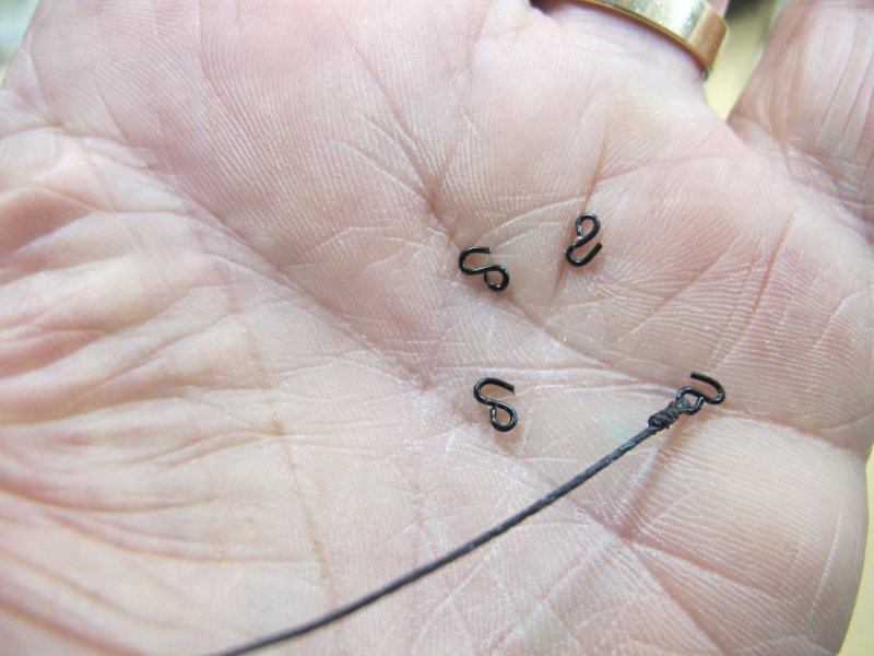
Lower Main done. After a few mistakes and frustrations, I can move to the lower foremast. Biggest hassle was the Futtock shrouds and the neatest way to secure them. The little hooks at the top were OK but the lower ends seem to take a turn around the futtock stave and are then seized to the shroud. Doing neat seizing in-situ seems quite difficult but the second side (starboard) started to look OK. I finished off the tiny seizings by passing the end back between the futtock and shroud plus a tiny drop of glue on the backside (out of sight!) Next time I'll try and do it neater!
This is just a personal ramble about my faltering learning curve.......😏
Pat
- GrandpaPhil, BANYAN and SIDEWAYS SAM
-
 3
3
-
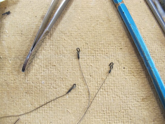
After a bit of searching my browsing history, I found my source of the ratline gadget - thanks for the tip Johnny 😊
Pat
-
Thanks Pat- not my idea but a good one!
Chris - if you are referring a few pictures back, they are test prod tips - any electronic shop should have them. They have a nice little spring hook to grip stuff😎
pat
-
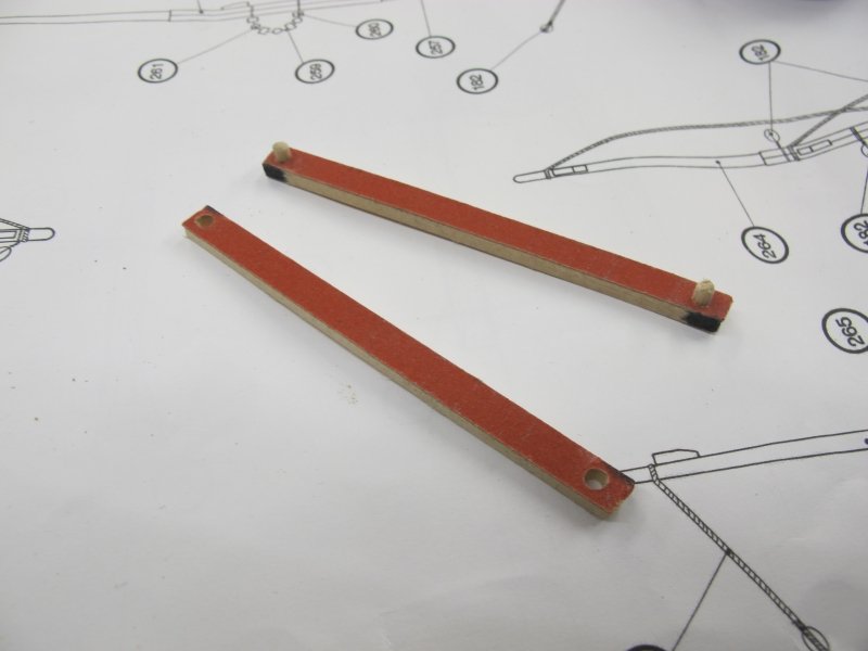
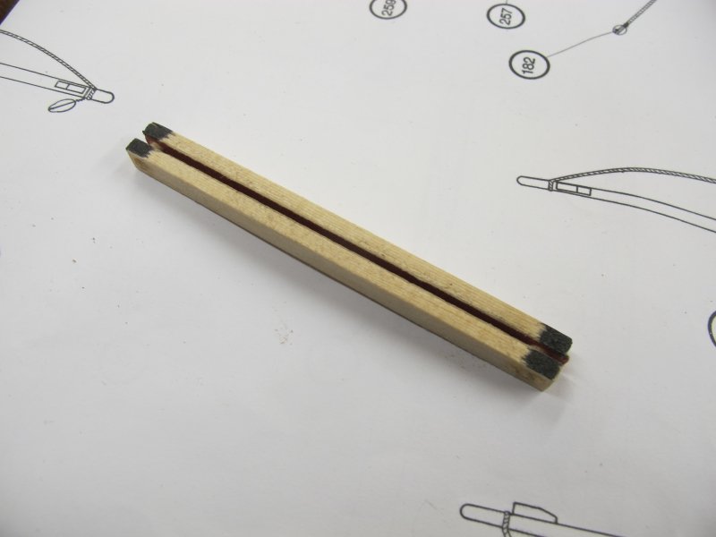
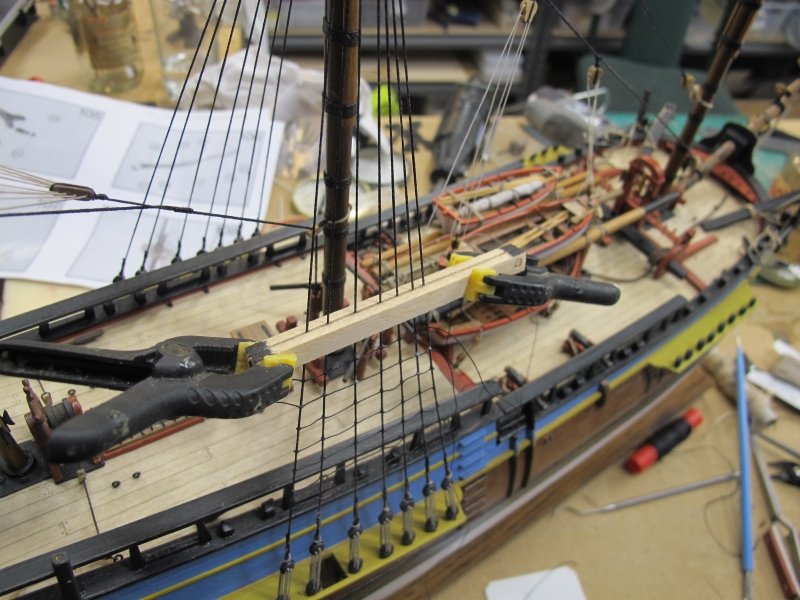
More progress on a rainy day. Tying the ratlines is always a lengthy chore but while researching how others did it, I came across a simple jig to get the spacing even and parallel. A couple of wooden strips of the desired spacing and lined with some fine grade sandpaper could be clamped each side of the shrouds and provide a reference for each row of ratlines which can be tied to the shrouds and then gently pushed down against the jig and fixed in place with thin PVA after removing the jig. Only tool used were fine tweezers.
I added a couple of 3mm dowels to make the jig easier to locate and clamp in place. The BIG bonus I found was that considerable force can be exerted on the shrouds while tightening the clove-hitches and end knots - it made the job a cinch 😎 I used 220 grade paper but may change to 800 as the coarser paper may scuff the shrouds if not careful.
I still haven't perfected the method yet but I did about a dozen ratlines on the main mast in about 30 minutes!
If I find the reference for the idea, I'll mention here. Someone on MSW I think. Thank you 😃
Pat
- GrandpaPhil, goetzi73, Fernando E and 1 other
-
4
-
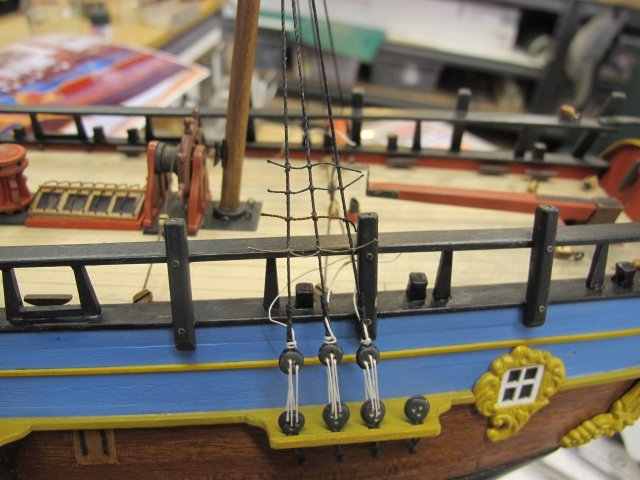
Experts - look the other way 😉 My faltering attempts at the main rigging is going OK but because I seem to find better ways to do the job as I go along, the end result is a little inconsistent. But then the replica has a few variables too. My biggest area of experimenting is the selection of 'rope'. I sourced a few different brands made by the various kit manufacturers (Mantua, A.L., Billings, Corel) and each has its ups and downs. I am also using Gutterman sewing thread - particularly the thin linen which is virtually 'hairless' but not very flexible at small scales. I am doing the lanyards on the port side with it (the off-white) and using Corel .25mm on the starboard. The shrouds are Mantua or Billings - both seemed much the same but needed a good feed of black wax. The Syren servo-matic is doing an OK job on serving the shrouds around the masts but I am cheating and only serving the top two or three shrouds 😊 - where they can be seen. Slow progress - about 3 days worth so far and about 1/2 way around the lower set of shrouds.
Although I have built a ship model previously, it was unfinished (a common result) and a larger scale (1:48). Also, I didn't try to do fancy knots and other refinements. It all adds to the great experience ship modelling is.......
As always, I have watched many helpful videos on Youtube and read many of the build threads here on MSW. Using two wire links to hold the upper dead eye in place while measuring the shrouds lengths is great - the two deadeyes stay in exactly the right relationship while the shroud is pulled taut and tack-glued to the block. Etc........
Pat
ps sorry about the dust everywhere - I must make a simple dust cover.
- jock2000, GrandpaPhil and SIDEWAYS SAM
-
3
-
I see what you mean about that mass of shrouds blocking working room!
Pat
- BLACK VIKING, EJ_L and J11
-
3
-
Good thing old ships had a little mast down the back for apprentice model ship builder to gain their skill on 😉
Having sorted my martingales from my futtocks, I have some early attempts to gain skills and techniques at shrouds, ratlines, futtock hooks, dead eyes etc etc......it is getting better as I go but I'll not replace the earlier bits despite their faults. Little things like remembering my way around clove hitches and how to get a simple single knot in the right place before tightening - easy now!
The details may not be AOTS perfect - the plans are often quite wrong but I'm continuing to use them as a guide unless I can see the alternatives! Most of my details are gleaned by the great builds on this forum. Dave Rowe, Banyan and many others.......thanks folks 😎
Pat
Pat
- GrandpaPhil, BLACK VIKING, BANYAN and 1 other
-
4
-
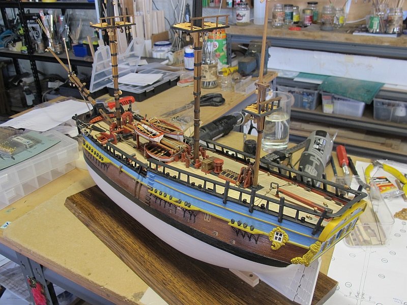
Thanks folks - always nice to reach a milestone - only the rigging to go. Only the rigging? what am I saying - maybe two tots of rum (not sure if Cook carried it............)
-
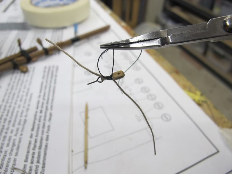
At last, a small milestone reached - the masts completed and fitted with a myriad of blocks as per the A.S. plans (albeit probably not accurate). The blocks were secured with rope and eyebolts using .5mm thread and .25mm seizing. Tested my 75 yo eyes and fingers just a little but using the Youtube video by J Brent, it all became clear and eventually - easy!
Some of the blocks may have used iron strops through the eyebolts but I just stuck with the A.S. plans and the rope fixings. I'm happy with the final effect and was a learning experience (as is it all!)
now I can look forward to the standing rigging - I guess starting with the shrouds.......to seize the shrouds around the masts or not - will it be even noticed. I'll have to do some reading. I have Syren's little wooden seizing device so........
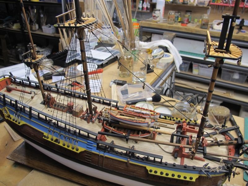
The lower mast sections have been aligned and glued in place - she almost looks like a ship
")
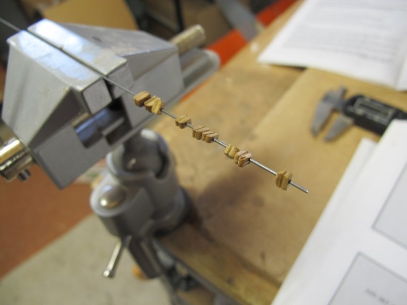
The little blocks I found easy to work with when slid over a piece of steel wire - it made sanding and staining much easier...
Pat
- John Cheevers, JpR62, SIDEWAYS SAM and 3 others
-
6
-
Hi Phil - I'm always keen to watch a scratch-build. Esp. the thinking, pondering and general "how am I going to do that" stuff 😎 I know it'll be a while before she's underway but great to share the pre-build thoughts!
Pat
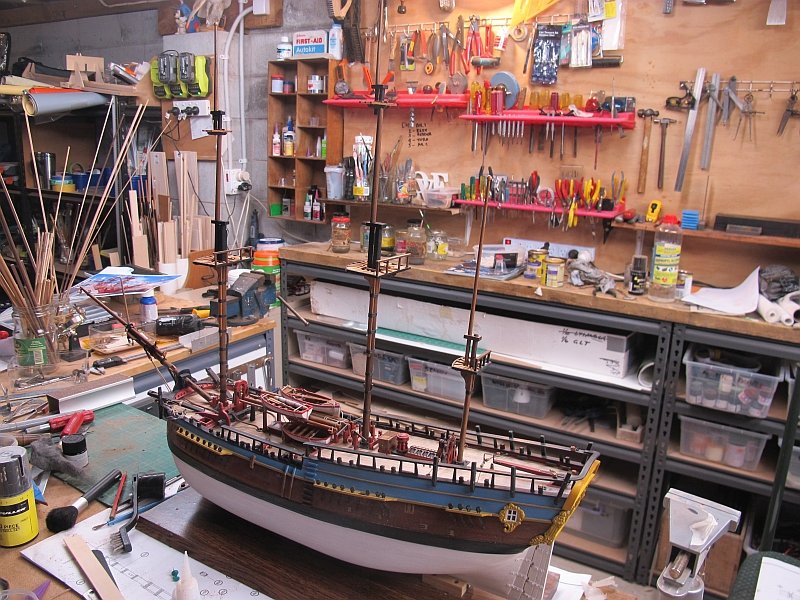
-
Thanks Jag - I hope you pick up some info from reading my stuff - mostly about what not to do! A very steep learning curve but the way ahead is gradually becoming clearer!
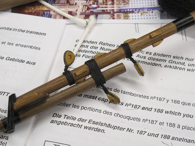
The current stage is something I've dreamed about - the real rigging is fast approaching😊 I have about a hundred or so blocks and other stuff to attach to the three masts before the proper rigging so that can await another day. Many of the blocks must be fitted in-situ so it will be a bit tricky until I get the hang of it. The mast are still in 2 or three sections to allow the various shrouds to loop around the top of each section.
I discovered a handy technique to finish of the mast woolding - the thread used was given a good rubbing with black wax and then after everything was ship-shape, I carefully played the heat gun over the wound thread and the wax neatly melted itself into the binding and looked a lot nicer - imho 😉
So six months work so far - faster than I'd expected!
Pat

- GrandpaPhil and SIDEWAYS SAM
-
2
-
Great first effort Duane - as you have intimated, you have to be your most severe critic! Once you have finished, look critically over what you've done and vow to not repeat the inevitable mistakes next time (i'm assuming there will be a next time 😉) I'll need a dozen boat builds to get enough 'next times' to fix my mistakes but learn I will!
Now, what's next? ...... Pat
-
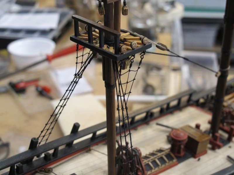
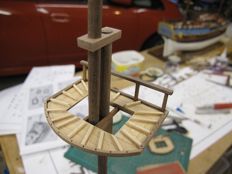
A little more progress....the limitations of the A.S. kit become more obvious as I becomes more familiar with real-life ship building practice! I'm sort of glad I don't have access to the AOTS book of this ship or I'd be 1 step forward and two back all day!!! The appalling instructions (combined with my gross ignorance) make for a bit of frustration. For instance, nowhere is it mentioned to modify the 'hounds' brackets to give a top angle that will make the tops platforms level. I should have looked more closely at the plans and noticed. I'll sort the mizzen later....😒
After completing the main and fore top assemblies, I found the hounds brackets provided were a little undersized (same as mizzen) so I made some more from scrap 2mm stuff in the kit.
Now I'm trying to figure out how those timbers running up each side of the masts are fitted - wrapped around the mast? recessed to fit over it neatly???? Must look at the replica. I'm not sure of their function - to protect the mast from ropes rubbing against it? Using the dowel provided, there was not enough meat to make and squared-off sections so I'll fudge something 😉
But progress is being made and new stuff learned.
Pat (going inside as it's freezing out in my shed)

- BANYAN, SIDEWAYS SAM and GrandpaPhil
-
3
-
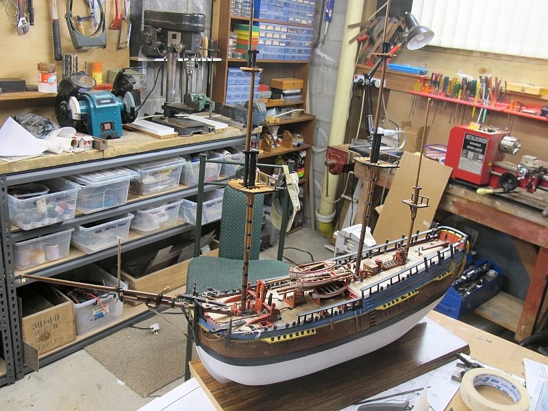
I'm still going.....
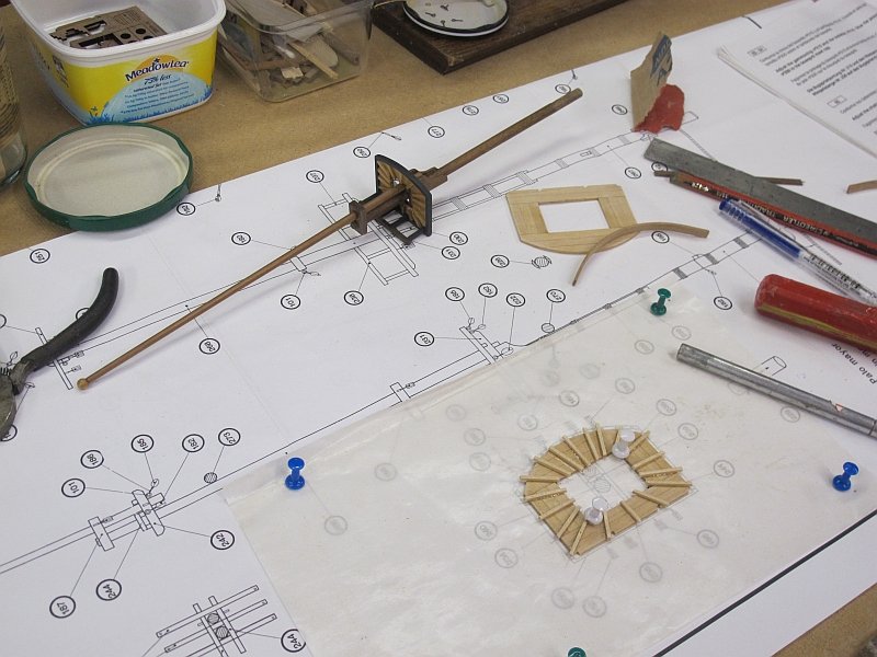
After blundering my way through the bowsprit, the masts needed looking at - not particularly tricky - just the usual nautical gobbledy-gook to learn and a look through the relevant pages of my Charles Davis books and others, helping to understand the various parts of the mast sections and the complications of joining the spars together.....so I started with the mizzen. No real problems as it is quite a bit simpler than the others - and being smaller (and maybe less obvious) I could make mistakes and get away with it. A.S. have reasonably good plans and diagrams of the mast assemblies and there were few problems. The area where the upper and lower sections join is perhaps not-quite-scale with the spars being left round in section but I may do better on the fore and main.
Assembling parts over a plan on grease-proof paper is how I built large model aircraft for many years and brought back a few memories...........enough waffle and back to the building.......
Pat
![IMG_1233[2].jpg](https://modelshipworld.com/uploads/monthly_2019_09/535512151_IMG_12332.jpg.01957c0d83865bffd52a38982dd22d7f.jpg)
- GrandpaPhil, SIDEWAYS SAM and BANYAN
-
3
-
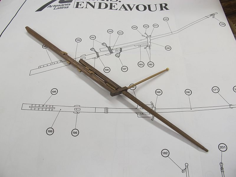
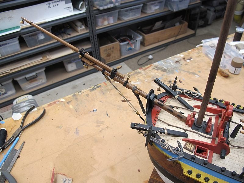
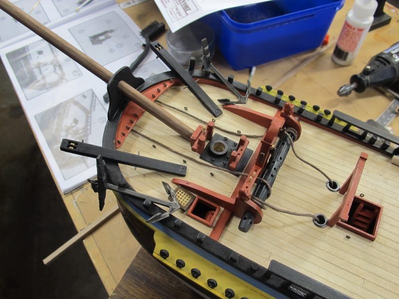
After a week or so of stop-start building/cursing/rebuilding etc, etc.....I finally have my first spars fitted - the bowsprit. Lots of learning here- how to taper spars, fixing tiny blocks to spars, etc. Good place to start here on the 'sprit. A lot of details not provided in the plans but reference to the many builds here usually gives one a choice about how it should look! Again, my Endeavour will certainly be MY Endeavour 😉 A real learning experience. But I've proved my aging fingers can fix tiny blocks and research how to do stuff - Youtube is a great resource! Some of the rigging will be at odds with other builds so - I'm sorry if I get it wrong. It's a process of learning the skills, nautical language, resources and the materials to suit my temperament. So, I have a fitted bowsprit. Now I can ponder the mainmast!
Not sure if the yards should be fitted after the standing rigging.......I guess they can still be installed later.
Pat
-
Hi Jim - a reciprocal greeting! Good to see a fellow rc aircraft builder her on this forum. I dont feel so bad at having almost vanished from rcgroups 😉.
Poor kits seem quite common in the ship arena but it can give one scope to improvise and make it your own. My A.S. Endeavour can be made into a fine model as many on this forum have done but it is not a great kit - lacking in the instruction area mostly. But, research and some imagination can work wonders.........I'll keep watching.
Pat
-
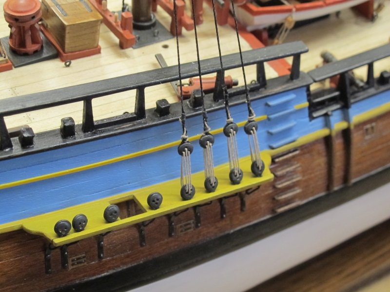
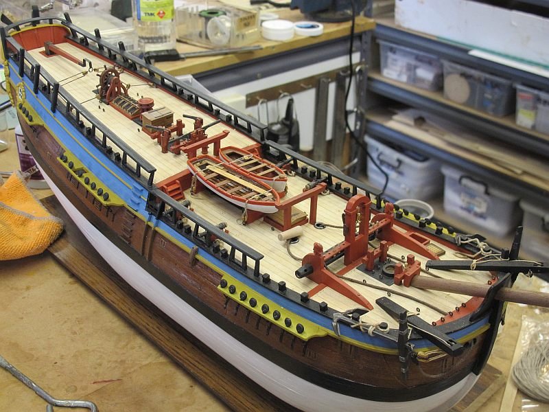
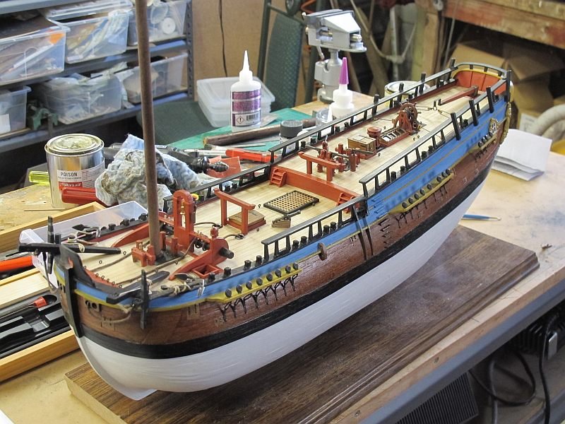
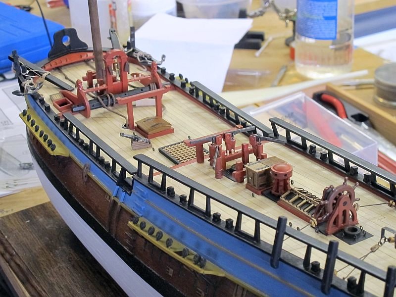
Having made the decision to go (more-or-less) with the A.S. rigging, I fitted out the decks with all the fittings indicated on the plans. For once, the A.S. rigging and spars seem well documented with many detailed drawings in a step by step manner. Still that annoying thing of having to refer back and forth to get the dimensions but at least I know what is needed. I am aware the model is quite wrong in many ares but as I am mainly concerned with learning the terminology and techniques, I'll stick to the plans and make small changes when/if they are needed.
So rigging - here I come - at last 😊
The cleats provided seem a bit on the large size (12mm X 60 = 720mm long!) but I may be mistaken.....
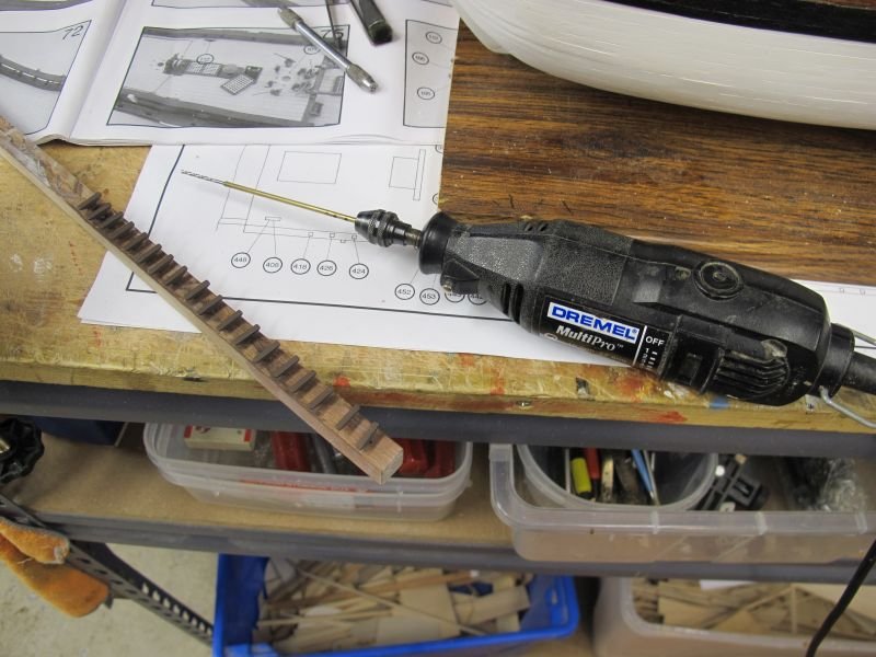
A handy extension for a 1.5mm drill - the bit is CAed into some tube - got some holes done in difficult places.
...for better or worse...Pat
-
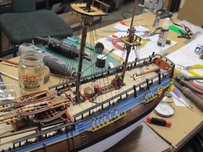
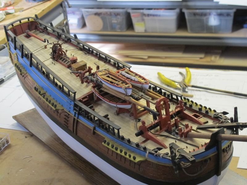
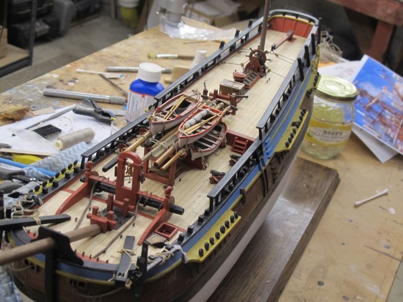
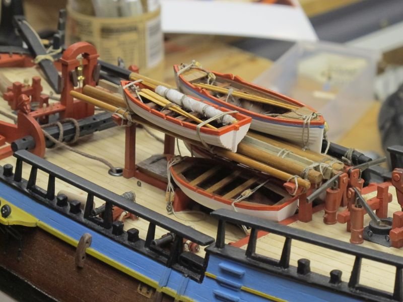
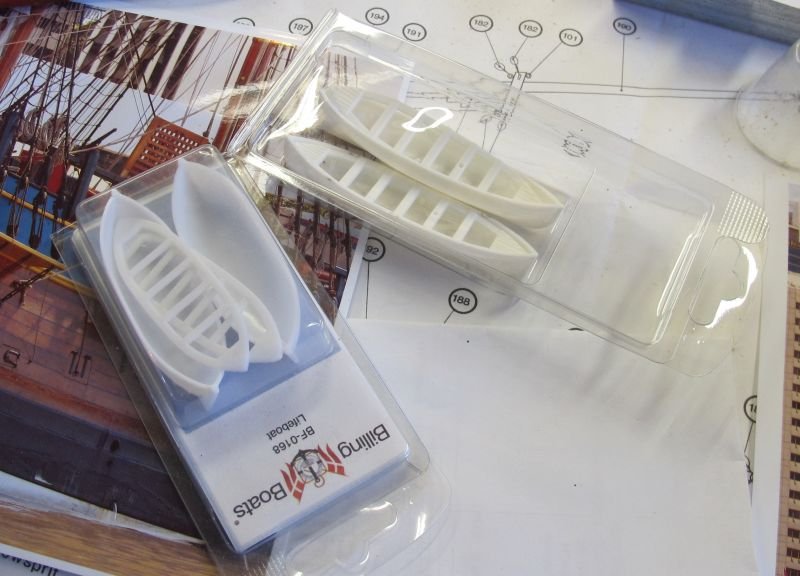
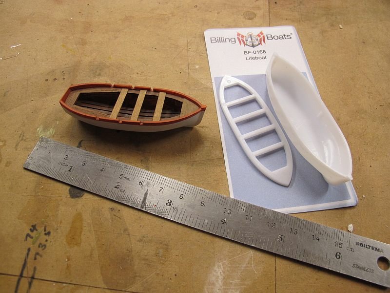
A bit of a lull while I got on with some sundry stuff- I had raise the forward gallows a few mm, add some sundry spars and spare planks and finally build another couple of boats. The basis of these two top imaginary boats were as before, a Billings kit of two plastic 20th century lifeboats but some not-so-subtle modification and lots of added woodwork they look just a little bit like various examples I've seen on this and other forums. Apologies for the lack of fidelity but my imagination is happy 😉
I'm slowly gaining confidence at 'how to do it' and one day may even get it to be accurate! But not yet.....this is still very much the A.S. ship - warts and all. Just with my 'improvements'.
Still having fun.
Pat
- BLACK VIKING, GrandpaPhil and RussR
-
3
-
I searched on the 'net for some pictures on ships boats of this era being lashed to the deck - but my skills (or patience) didn't find what I wanted so I used some models on this forum for guidance and then did 'my own thing'. Some ability to tighten the fixings seemed desirable and I'd seen both dead-eyes and pulley blocks used - I liked the blocks and opted for the smallest ones supplied with the kit - about 4mm. They seem a bit out of scale but I'm happy with the look and have now got a supply of 3mm ones - for other bits later. My arrangement looks like it is accommodating boats of a different intended size (or were stowed in a hurry!) - most will be hidden under the spare spars and timbers. It all adds to the wonderful clutter on the decks of these early ships
Now on to those spare spars on the gallows.....
Pat
- GrandpaPhil and JpR62
-
2
-
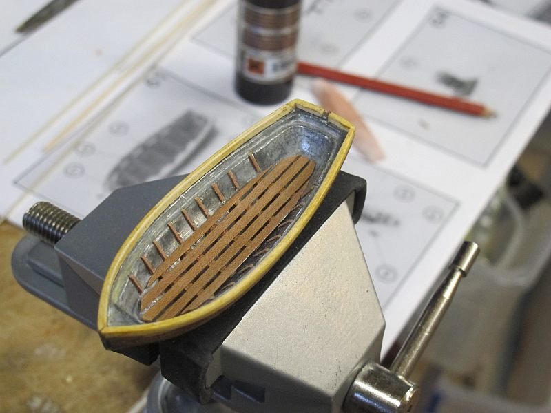
A bit of a break while other matters needed attending to! The four cannon are almost finished and fixed in place and two of the four ship's boats have been made. The kit-supplied boat was 'tarted up' a bit with 'duck boards'? and some rudimentary internal frames - just to see if it was worth it. Came out OK (I think). A second boat (dinghy?) was created from a cheap Billings plastic item - only a few dollars a pair. A transom and some internal modifications made it remotely dinghy-ish and will be OK when fitted out with stowed rudder and oars and buried under all the spare spars and a couple of bigger boats. What those boats will be is debatable! I have a pair of Billings 'life boats' that are a bit like whalers and can be bashed into something respectable. Reading the AOTS book of the Beagle, it seemed that ship's boats needed frequent replacement while on long journeys - replacements being sourced from friendly ports en-route. Mine will be only remotely like the real ship - whatever it carried
")
It's all good fun and this Endeavour will certainly be 'mine' . Now back to fitting and securing the lower boats in place and making a few more oars!
Pat


-
Johnathon and Dashi - thanks for your interest and input- it all helps
Pat
-
Hi Mike - thanks for being daring enough to scratch-build the Beagle
I had bought the AOTS and am slowly coming to terms with the nautical detail!
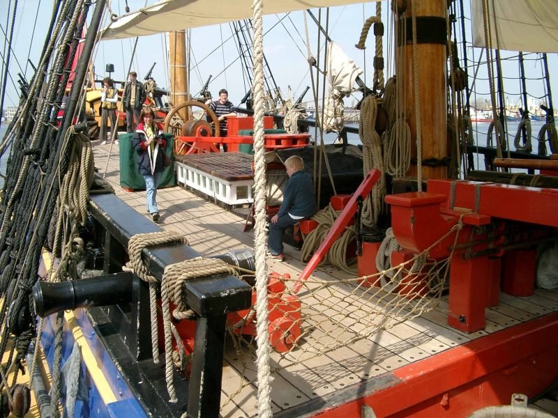
A small thing I don't quite understand is the function of the hammock storage along the sides of the main deck. Were the crew's hammocks stored there for airing? (surely they would have got wet). Did the crew sleep on the upper deck? I am a bit unsure!
Again, thanks for your build so far - it has given me some insight about an ambitious scratch build wa.......y down the track.
Cheers, Pat
-
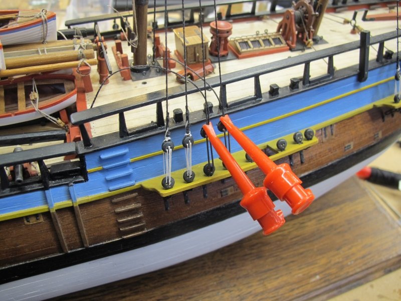
Thanks Cabbie - this whole project is bordering on 'too fiddly' for my ageing fingers and eyesight
I had a go at the cannons and am seeing a way to achieve what I need. The kit barrels and basic carriage work out OK but I'll replace the wheels with ones cut from 4mm walnut dowel. I'm still experimenting and think I'll just fit the heavy ropes that restrain the gun. It looks very small but is only a 4 lb gun and the replica shows them as quite tiny too. Watch this space ........ (not sure why !)
Pat

-
Back again - just a few small but time-consuming details done - the anchors were fitted and lashed to various posts up front. I studied all sorts of pictures but opted for something vaguely logical to secure the anchors. The A.L. instructions are of course, not helpful. But it looks OK (imho)
I also made the various skylights and companion way covers - lots of variations and options so I did a mix and match. I found the .3 and .6mm birch ply very nice in this job - very fine grain and easy to work with.
Next task are the four cannons. They must have been a very lightweight piece of gear - only a few pounds per shot? They seem small. Brass wheels were supplied but I'm using painted wood dowel - the real thing was wood so..........
After the cannons, there are many boats - up to four it seems. At least it's not as cluttered as the HMS Beagle that I'm studying the AOTS for. I might get enthused one day - smaller ship, bigger scale possible........who knows where it may lead 😊
Pat
HMB Endeavour by Pat Lynch - FINISHED - Artesania Latina
in - Kit build logs for subjects built from 1751 - 1800
Posted
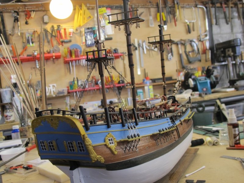
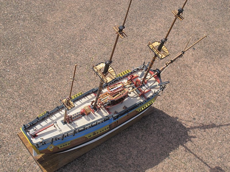
One small step for a man.........
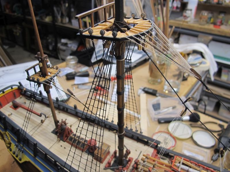
A minor milestone has been reached when the last (I think) of the standing rigging on the lower mast sections is done. Not perfectly, in fact even poorly in some places but I was happy to get here and happy to have learnt a lot on the way. The ratlines became easier - and in most cases, better executed, as I progressed. But I decided not to go back and improve what I've already done (particularly around the mizzen area) - I'd be rebuilding the whole thing 😐
Next stage will be to fit the upper mast sections and get the standing rigging done there. I'll leave the long back stays until the yards have been fitted to try and make more space for my 75 year old fingers 😉
A short break now while my wife and I go on a two week train trip from the North to the South of NZ with many stops and adventures along the way. Sadly this means I'll not be able to go and see the replica Endeavour as it joins the celebrations of European 'discovery' of NZ. Not a popular celebration with many Kiwis but I would have loved to visit the Endeavour.......
Back soon, Pat