
HOLIDAY DONATION DRIVE - SUPPORT MSW - DO YOUR PART TO KEEP THIS GREAT FORUM GOING! (Only 75 donations so far out of 49,000 members - C'mon guys!)
×


Egilman
-
Posts
4,377 -
Joined
-
Last visited
Content Type
Profiles
Forums
Gallery
Events
Everything posted by Egilman
-
 That looks super sharp!!! Crossing the Indian Ocean on her way to meet her fate..... (might not be, but that is what popped into my mind when I saw the pic) Excellent work, anticipating the finish now and your reveal.... EG
- 211 replies
-
- 5
-

-
- prince of wales
- tamiya
- (and 2 more)
-
excellent save brother.....
-
I agree, very much so, it's an almost 70 year old base design, of course upgraded any times... anything is possible, I've even seen some pics of the "A" models serving in 'nam with those side windows painted over.... the current ones are much improved over the originals...
-
It is monochromatic for sure, plain white always is, but bland? Not hardly...... That is a slick speedster my friend, the white gloss looks perfect..... The colorful decals will only make the slick white look even better.... Very Very well done....... (and a bit of envy)
-
Need a different take on this thought? With your skills Mike, I don't see how you can avoid it.... (chuckle)
-
There are ways to do soft edge without an airbrush, several ways in fact..... I'm gonna have to do one of my fav's in the future....
-
I think your doing a bang up job, that steel PE does try the patience though, but it looks to me that you got it under control.... It's coming out beautifully..... Really gonna look the business....
-
Most of the FM-1's served in the Atlantic aboard Bogue class escort carriers, in the Pacific, it was primarily FM-2's aboard the Casablanca class escort carriers.... and when they sent an escort carrier to Britain under lend-lease, it came with Wildcats both FM-1's & 2's The USS Core joined the Fleet at Tacoma WA where she was built in early '42, she did her working up off San Diego in early '42 then shifted to the Atlantic for escort duties eventually forming up in a hunter killer group. She survived the war eventually being stricken in the '50's she was credited with several u-boat kills during her war period..... Atlantic aircraft camo aboard the hunter killer groups was indeed Gull Grey over White or Aircraft Grey.... When the US Navy switched to Grey over Grey camo fleetwide in early '41 it was found to be very effective in hiding the aircraft from surface recognition until the aircraft got within firing range..... So they retained the scheme for the hunter killer groups..... in the Pacific where surface targets were not the priority for fighter planes, they switched the the Blue over Grey scheme in late '41.... I don't believe the Wildcat ever wore the three color scheme of dark blue over lighter blue over grey you see on some corsairs and other carrier aircraft, but I could be wrong on that....
-
They should be closer to the color of the surrounding bulkheads, a bit lighter as they did stand out in the sun a lot and were exposed to salt spray a lot more...... They do look good, excellent scale representation....
- 211 replies
-
- 5
-
-
- prince of wales
- tamiya
- (and 2 more)
-
All three for only 40 quid? that's a good price my friend...... That's actually a very good kit for a first time armor builder, good details and wide variation in paint and markings, Panthers were everywhere except Africa.... As your first foray into the mud hog world, you couldn't get a better set of kits..... I'm sure the crew will be here in case you have any questions, it is a pretty straightforward build.....
-
Mike, the color scheme is prewar grey over grey..... (Although the yellow light may be affecting the color a bit) The squadron according to the label is VMF 223 that would be a marine squadron, the location would be Guadalcanal, Henderson field, late '42....... On that basis the six guns is wrong (they would be flying F4F-3's with two guns in each wing) and grey over grey is wrong, markings are correct though. The actual aircraft depicted is Marion Carl's who as a charter member of the cactus airforce, (a survivor from the marine buffalo squadron at Midway) was the leading ace from the 'canal... 12.5 of his 16.5 victories came in the F4F..... the colors were blue over grey.... (he got two planes at Midway flying a Buffalo, and receive a navy cross for it seeing as he was one of only 10 that came back) He retired as a Major General after commanding marine aviation in Vietnam.... Oh yes and they were still blue over grey at Leyte..... and it was probably correct being an F4F-4....
-
I agree, looks great in fact...
-
They always look good like that, but I've always found that they are more work than worth it.... but that is just my opinion, some guys swear by them and add them to everything.... And believe it or not, it's only aircraft jocks and us modelers that know that they have them, most people haven't a clue.... leaving them off will be no big loss if you so choose.....
-
I'm guessing here but those pop-up panels on the trailing edge of the cowl would be the cowl flaps..... They are what controls the airflow around the engine cylinders..... they are only open fully when the engine is on and throttled up, otherwise they are usually almost closed...... Kit parts usually give a half to three quarters open position for them but on a carrier hangar deck, they would usually be closed.... (unless maintenance was happening)
-
Oh I'm in, an inscale, gloss white finish, I'm sure you'll do it justice.... I stay away from high gloss white finishes, never been able to get one to lay correctly, they always look like big blobby drips....
-
Delahaye 135 by CDW - FINISHED - Heller - 1:24 - PLASTIC
Egilman replied to CDW's topic in Non-ship/categorised builds
Job well done on a difficult kit my friend, I"m sure with the experience, if you did another it would come out even better! -
Inkscape does it about as well as Corel does which isn't very well at all.... But there is a solution out there.... pricey and huge learning curve, but it's designed to convert scanned drawings to vector drawings.... and it is integrated with autocad... Autodesk's Raster Design..... Check it out, designed specifically for those engineering offices that have tons and tons of paper drawings that they need to bring into the digital age.... It does take a while to figure out how to use it.... I found that it is just easier and faster to just simply trace over the drawing..... Get you where you want to be a heck of a lot faster..... EG
-
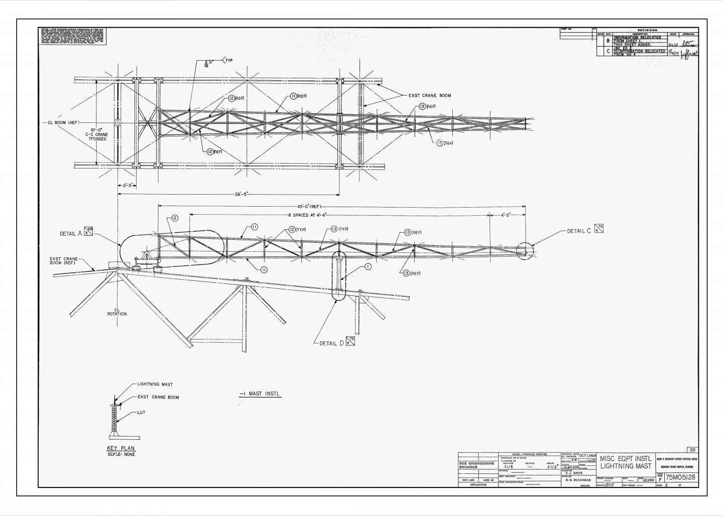
Ok I just tried anyconv.com on the NASA image I posted above of the LUT Lightning Mast.... The input filename.... 75M-05128-Sh2.jpg The output filename.... AnyConv.com__75M-05128-Sh2.dwg Took all of about 20 seconds for the conversion and getting a download link..... Tried to load in Autocad 2021..... This is what I get.... It doesn't output valid autocad files... only one test on a very simple drawing, but it pretty much the same on all such sites for serious technical drawings...

-
I've tried them all..... But, the anyconv.com is one I haven't seen just yet.... For an example this is one of the drawings I want to convert..... None of the converters have worked this is a standard two color jpg 30x42 E1 sized paper.... it is the lightning mast from the top of a Saturn V LUT 300dpi..... If a converter can't handle this simple drawing then it won't work... I've also tried it on drawings that I've cleaned up from US Navy Booklets of General Plans, they don't work there either There is a process for doing this in cad..... I believe it is posted right here in the site..... Lemme check... Yes by Rex Boocock.... https://thenrg.org/articles/creating-new-ship-drawings (downloadable as a PDF as well) Then there is this by Wayne Kempson.... https://thenrg.org/resources/Documents/articles/DraftingShipPlansInCAD.pdf Excellent treatises on how to do it.... That's the methods I use... EG
-
Delahaye 135 by CDW - FINISHED - Heller - 1:24 - PLASTIC
Egilman replied to CDW's topic in Non-ship/categorised builds
Very correct, in production auto coachworks of the day, usually 5-7+ coats hand rubbed which produced not only a very reflective shine but a deep color depth which looked like you could "see" into the paint, the color was solid but has this almost surface transparent effect, it can't be duplicated with clear coats.... This is the reason that custom shops doing lacquer finishes will usually do 20+ coats hand rubbing between each coat to produce the very smooth and rich finish that custom car owners cherish and will pay big bucks for.... Bonus is the lacquer dries so hard you seldom need a protective coating for them.... The closest they have come with enamels is the 2k or 4k diamond finish products, but in my opinion, they are not the quality finish of hand rubbed lacquer..... Basically the point of the diamond finishes are to produce the shine of lacquer without putting in the work prep needed for a good lacquer finish...... They will never reproduce the depth of color a properly applied lacquer finish will produce though..... -
Delahaye 135 by CDW - FINISHED - Heller - 1:24 - PLASTIC
Egilman replied to CDW's topic in Non-ship/categorised builds
A good job on a very difficult model my friend..... If anyone else is interested in taking a shot at this, they are available as they are still being produced by Heller.... In September of 2016, Airfix Model World published a build article on this kit, by Matt Bacon, pages 78-86. It does mention the difficulties with what they call the "front wings" (meaning the front fenders) He also says it's not for the beginner, but AMW lists it as an intermediate skill model.... It is a classic car, and a classic Heller kit.... 1938 Delahaye 135M Coupe Sport..... Want one in real life? save your pennies, about a billion and a half's worth... {chuckle} -
Having studied steel naval warships for many decades, (mostly US Navy) I've yet to see an image of an in-service warship allowed to get that rusty.... (but I have seen it in mothballed/reserve fleet ships) THERE! it's been said..... Now that it's been said my friend, I'm gonna tell you what matters most...... YOU! and how you view it.... It is going to sit on your shelf and represents your vision of how it should look.... so it should be a display of your talents.... and this is an expose of talent in prodigious quantity and ability.... Don't worry about it my friend, people who bring it up either haven't researched one nor walked a deck... I would say that they haven't even built a model before so they do not understand what they are seeing.... I'll admit that I'm not a fan of heavy rust on anything, (even my tanks look clean) but what I'm seeing here is modelers art at a level that few can match.... Very, very well done...... EG
-
That is stunningly beautiful my friend, a brilliant execution of a powerful animal in action.... Understated but elegant as well...... Your getting very good at figures brother....
-
Delahaye 135 by CDW - FINISHED - Heller - 1:24 - PLASTIC
Egilman replied to CDW's topic in Non-ship/categorised builds
Wow! nice work..... That fender and hood assembly is going to be a nightmare, doesn't appear to me to be any clear mounting points except the fender points on the body, the front fender seem to just float with no clear connection point.... (according to the instructions) So my suggestion would be to follow the cowl/hood line, they have to match as they set the body lines-hood position, the rear fender points set the fender location, and devising a place/way to securely connect the front grille... A nightmare in reality.... An issue would be the tips of the fenders molded to the body, that joint has to be clean, almost perfect, and will still be the weak point..... I would make sure their mating surfaces are square and clean on both the body and fender.... the two bumper mount holes in the fender part should line up with the ends of the frame rails if it is accurate.... This will locate the part vertically on the front end... with the bumper supports going thru should be a good locator for the fenders... But checking that the hood lines up with the cowl is where any inaccuracies will show.... A beautiful kit, a real challenge in assembly.... I found a build log from 2015 that shows this problem on this exact kit..... (don't know if it is permissible to post such here, if it isn't please delete it) https://skidsplace.forumotion.com/t2468-1935-delahaye-135-heller-1-24 Hope it helps Craig... EG

