
MORE HANDBOOKS ARE ON THEIR WAY! We will let you know when they get here.
×

ScottRC
-
Posts
559 -
Joined
-
Last visited
Reputation Activity
-

 ScottRC reacted to MrBlueJacket in Red Jacket by MrBlueJacket - FINISHED - BlueJacket Shipcrafters - Scale 1/8" = 1' (1:96)
Working this week, the foremast is finished. Mainmast next......
-
ScottRC reacted to mtbediz in San Francisco II by mtbediz - FINISHED
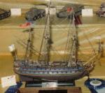
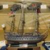
Hi friends, I'm happy to report that I finally finished my San Francisco II. It took my 6 months. I hope you like it.
-
ScottRC reacted to mtbediz in San Francisco II by mtbediz - FINISHED
I finished ratlines and as i mentioned before i am making lifeboat myself. I will not use metal cast lifeboat given in the kit.
-
ScottRC reacted to mtbediz in San Francisco II by mtbediz - FINISHED
I remade bilge pumps from wood instead of metal cast pumps given in the kit.
-
ScottRC reacted to mtbediz in San Francisco II by mtbediz - FINISHED
Lifeboat and anchors are complete, masts are still in progress
-
ScottRC reacted to mtbediz in San Francisco II by mtbediz - FINISHED
Lifeboat trial. I am trying to build lifeboat from wood instead of metal cast one given in the kit. I hope i can success.
-
ScottRC reacted to Jond in Aphrodite 1853 by jond - 1:96 - RESTORATION - Boothbay Maine ship
Post 2
The hull part 1
I am feeling my way here so I am not sure how far we may go. There is a lot this hull needs but if I go crazy one might ask….as Roger already did ask…..why am I using this old hull, it seems more work than carving a new one........I can attest Roger is right. So let’s try better to stay with the basics
Easy ones
The red paint must go! Then the decision to add either yellow metal / copper plate as was in vogue according to Crothers on most ships / freighters of the time. He also said that some yards sent them out painted and the owner then added plating and other items in dry dock before her first outing. We shall try to do more research on whether copper was part of the Boothbay Scope, but for now I have no reason not to include it. So for the choices, we will first clean up the rough spruce log look and paint a simple light green to simulate patina copper/ yellow metal [ contained more tin I read]
I will share a fun experiment that I thought I might try when it comes. The teaser! lets look a a little progress on the hull
Ap-006 So the first thing I did was to cap off the hull with a simple sheet stock decking. I hemmed and hawed about stain colors and ended up with gunstock. A bit too red for some but with sheet stock the grain comes through and blows the scale, so I went dark. I then after one coat of poly added pencil lines on the joints and cut all planks to be 12 feet on three alternating rows. I say all this hoping someone says right or wrong. Please note the added 1/2 poop deck that matched up with e focsle deck on height. The block cut outs are for cladding the deck houses again as per the Alna deck layout plan
Ap-007 The second thing is to get the masts laid out and drilled. I want to try to reuse the old ones and their methods was a minor countersink [ 1/16”] at full diameter and a pin. Here I laid out the rake per Crothers on the yellow graph paper and aligned/ shimmed the drill and hull to be square for the pin hole.
Ap-008 Here is the first bulkhead. It is ¼[ 2 feet] with waterway inboard. That is 1/16 too low but here I am compromising to fit the preordained low focsle deck. More on that later
Ap-009 I had to use lead weights to bend the bulkhead to the existing shear. i wanted to get it in place before fixing the hull...that has several problems
Ap-010 just as an import glance I want to share the existing spars that we need to study. I want to rescue them but there are a few dimensional issues. The good news is when I took Crothers dimensions to locate them, the fore and Main mast feel in the same hole almost perfectly. The mizzen was a bit aft but that makes perfect sense as there was no poop deck on the original model, and the rake of the mizzen mast moves the opening on the poop deck right back to the right place. this is good news.
All for now
Jon
-
ScottRC reacted to rwiederrich in Great Republic 1853 by rwiederrich - FINISHED - four masted extreme clipper
I dry fit the mast against the others to see how I'm progressing.
Rob
-
ScottRC reacted to rwiederrich in Great Republic 1853 by rwiederrich - FINISHED - four masted extreme clipper
Need to finish up the foot ropes and stirrups after I added the gin block and all the eye bolts needed for blocks and sheet control eyes.
-
ScottRC reacted to rwiederrich in Great Republic 1853 by rwiederrich - FINISHED - four masted extreme clipper
Spent some time working on the GR today. Trying to finish up the Mizzen. I worked on the royal and topgallant earlier and I finished up the basics of the topsail yard...now working on the topsail yard with its gin block lift rig.
Here are a few images.
-
ScottRC reacted to rwiederrich in Great Republic 1853 by rwiederrich - FINISHED - four masted extreme clipper
Scott..that sounds fantastic...love to watch that come together.
Rob
-
 ScottRC got a reaction from Cuda1949 in New here and ring stuck in ship
Try your local auto parts store and ask for a flexible mechanical parts retriever. They come in two types, one is magnetic, the other has a set of claws you work with your thumb. Some even have lights. I have one that is 1/4" in diameter that I have used many time in retrieving stuff I dropped into tight, enclosed areas.
-
 ScottRC got a reaction from mtaylor in New here and ring stuck in ship
Try your local auto parts store and ask for a flexible mechanical parts retriever. They come in two types, one is magnetic, the other has a set of claws you work with your thumb. Some even have lights. I have one that is 1/4" in diameter that I have used many time in retrieving stuff I dropped into tight, enclosed areas.
-
 ScottRC got a reaction from Piet in Red Dragon by Vivian Galad - Artesania Latina - 1:60 - modified
Welcome back Vivian and congrats on the marriage. I'm excited to see how these sails turn out. They are looking very nice.
Scott
-
 ScottRC got a reaction from popeye the sailor in Red Dragon by Vivian Galad - Artesania Latina - 1:60 - modified
Welcome back Vivian and congrats on the marriage. I'm excited to see how these sails turn out. They are looking very nice.
Scott
-
 ScottRC got a reaction from Vivian Galad in Red Dragon by Vivian Galad - Artesania Latina - 1:60 - modified
Welcome back Vivian and congrats on the marriage. I'm excited to see how these sails turn out. They are looking very nice.
Scott
-
 ScottRC got a reaction from lmagna in SS Stephen Hopkins by schooner - FINISHED - BlueJacket Shipcrafters - Liberty Ship
The crimping tubes are great. I learned of them when rigging the control wires on a 1/32 WW1 biplane. Saved me a lot of pain and frustration.
-
ScottRC reacted to shipmodel in USS/SS Leviathan 1914 by shipmodel - FINISHED - 1/200 - troop ship/ocean liner
Hi all -
Another Sunday – well, Monday – another building installment, after a nice diversion into engineering.
Working now from the middle funnel down, I began with area between the middle and forward funnels. Here is the relevant section of the plans. Photo analysis provided the rest of the information needed.
I started with the bases of the funnels themselves. Here are shots of the middle funnel and the forward one. The colors changed from the troop ship to the liner, but the fittings were the same.
There are two types of small vents that had to be made, one with two tapering round plates, the other with a flared cross-head. Of the two, the flared head of the second made it harder to make, so I started with it.
After a bunch of failed experiments, I found that I could make a flare in a tube with a pencil. A tea light gave me enough heat to soften, but not melt, the plastic. I held the pencil steady about two inches above the flame and rotated the plastic for even heating. The picture is a bit off, since I found that heating more of the pencil gave me a flare just on the very end of the tube.
The flare was cleaned up a bit with sandpaper, then cut to the desired length on the Preac. A short length of brass tube was cut and glued into the flared tube, then a shaft was dished at the top and attached.
There are two sizes for these vents and lots of different heights. After measuring and cutting the shafts to length the open ends were filled with toothpicks which also acted as handles for painting. Then the wood was cut off flush and drilled for a soft iron wire that will secure it to the model along with white glue.
The round top plates of the other vent were made by punching out three sizes of plastic disc and stacking them so it looks like there is a gap between the top and bottom plates. This was attached to a length of dowel, which was used as a handle to sand down the top plates to a flat angle.
Here are those fittings at the base of the forward funnel. I am a bit unhappy with the slightly crude look of the round vents. I could not get that edge as sharp as I wanted, since thin plastic will not take the same detail as metal. But to worry about that level of detail I would have to have 9 years to finish the model, not 9 months. All of life and art is a series of tradeoffs.
Next was the area of deck just forward of the middle funnel. Here is the plan. There are a number of structures, but they are all too short to show up on any profile plan that I have, although an artist’s rendering of the cross-section of the ship gives some idea of their shapes.
Photos of the area were studied closely to make out the shapes that fit the plans. But most of them are from the liner period, and some seriously creative interpretation had to be done to fit what was seen in the few troop ship photos showing this area.
For the most part, the structures here are rectangular, though of different heights and a few with sloped roofs. Most have rectangular or square skylights which will be represented with dark decals. However, in the center of this photo there is a ducted fan that I call, for obvious reasons, a snail.
This and other photos show this type of machinery in lots of other locations around the upper deck. They come in several sizes, with varying details, but they all follow a similar pattern. There is a round flat body with a motor on one side sitting on a motor mount. There are intake and exhaust ducts coming off at various angles, with various end caps or fittings.
I experimented with styrene and resin, but I am basically a woodworker. Each body was sliced from a hardwood dowel, as was the motor. I did not try to do any detailing of the motor except in the largest sizes. When lying down the disc has its grain running vertically, so it is easy to line up a knife blade and press down vertically. The wood splits cleanly away. Ductwork the width of the body is glued to the cut face and rounded to curve into the disc. It is topped, in this case, by a rounded square cap.
After priming, sanding and painting these snails were located, secured and attached to the ductwork shown on the plans or photos. There are two here, along with my best interpretations of the houses, skylights and vents. More than most other areas of the ship, this one shows the changes from the troop ship to the liner.
I try to check my progress regularly against photos to be sure that I am not getting too far away from reality. Here is the developing troop ship from a low angle. I think I am on the right track.
Just forward of this area there is a large belfry. This houses the largest of five bells on the ship, and the one left over from the SS Vaterland. It was built up from 1/16” scale I-beams. The pieces were gently bent around a form and rubber banded there. A dip in simmering water and a dunk in cold set the U-shapes which were joined at the top at an angle. Cross supports were added and welded in place with liquid plastic cement. After painting the bronze cast bell was mounted.
Forward of the belfry is the curved roof skylight over the Social Hall with the individual lights represented by a custom decal. The camouflage scheme was carried up and over since it could be seen from the side. Photoetched railings and ladders were fitted in place as seen in the photos.
From the angle of the port bridge wing the model closely resembles the ship and is starting to get the busy look that she had. Nothing draws my eye as being off and, as they say, “If it looks right, it must be right. . . “
Another segment next Sunday, god willing and the creek don't rise.
Till then, be well.
Dan
-
ScottRC reacted to shipmodel in USS/SS Leviathan 1914 by shipmodel - FINISHED - 1/200 - troop ship/ocean liner
Thanks for all the likes and comments. And Marc, never hesitate to point out something that I may have missed. More eyes just means that fewer mistakes will get through to the final product.
With the model hull on the port side fully primed, it was time to figure out how to paint the complex and confusing ‘dazzle’ design that the troop ship bore.
Dazzle camouflage, called ‘razzle-dazzle’ by us Yanks, was developed in England during World War I in response to Germany’s use of unlimited submarine warfare. Credited to both a marine artist and a zoologist, the idea was not to make a ship invisible, as overall grey tries to do, but to make it difficult to estimate a target's range, speed, and heading. It was intended primarily to mislead the enemy about a ship's course and so to make him take up a poor firing position. It generally consisted of complex patterns of geometric shapes in contrasting colors that interrupt and intersect each other. It has been suggested that it works on the coincidence rangefinders used by submarines by making it hard to align the split images in the eyepiece. The clashing patterns look abnormal even when not seen through a rangefinder. Below is an actual photo of the USS West Mahomet. Try to find the bow.
As seen in this 1922 illustration from the Encyclopedia Brittanica, dazzle can work for single ships, but for a convoy the appearance can be overwhelmingly confusing.
Its effectiveness was analyzed after the war. Although British data is equivocal, among American merchantmen 2,500 tons and over, 78 uncamouflaged ships were sunk, but only 11 camouflaged ships sunk by torpedoes. No camouflaged US Navy ships were sunk at all. In the words of a U-Boat captain:
“It was not until she was within half a mile that I could make out she was one ship [not several] steering a course at right angles, crossing from starboard to port. The dark painted stripes on her after part made her stern appear her bow, and a broad cut of green paint amidships looks like a patch of water. The weather was bright and visibility good; this was the best camouflage I have ever seen.”
This may have been what he was looking at -
Fortunately I did not have to rely on photographs of the troop ship to get the dazzle design I needed. The National Archives contains drawings of the dazzle pattern for Leviathan. Here is the one for the port side. This and the several photographs of the ship taken during the war were my starting point.
Obviously, both the pattern and the photos are in black and white, but color was also a central part of dazzle camouflage. For Leviathan it appears from the different shadings within the various areas of the pattern that several colors were involved. The Brittanica page has a chart of all the colors used, but which colors went in which area? Fortunately, the Merchant Marine museum has a large painting of the ship in moderately heavy seas. It was done by Frederick J. Waugh, a marine artist who had been part of the American Camouflage Section which was responsible for designing the patterns for US Navy ships.
The painting was very helpful in identifying the look of the ship, but for model making it has some problems. Careful comparison with both the drawn pattern and the photographs reveals some inconsistencies in the size and location of some of the camouflage shapes, so I went back to the photos for the final layout. As for the colors, I was somewhat hesitant to rely on Waugh’s choice of hue and tone since he has other artistic factors to consider beyond exact reproduction. Instead, I went back to the color chart on the Brittanica page. It was clear that the page had yellowed somewhat, so I took the chart and adjusted the contrast, hue, and saturation until the background color of the page and the white color chip looked as close as I could get them, which is the lower set of colors. After consultation with Professor Smith, we selected 1 Grey, 3 Grey, 1 Blue Green, 2 Blue, and White.
With those decisions made I took the dazzle layout and enlarged it to the size of the model. Here it is, propped against the model. I should have put them side by side for comparison, but forgot to take the photo. So for comparison here is a shot of the port side from an earlier date. The red things are the backs of our dining room chairs.
To lay out the design I knew that I could not simply cut out the pattern. The model has too many curves that would distort the shapes, and I found that in any case the pattern did not accurately match the landmarks and dimensions of the model. I would have to draw the pattern on the model by eye. I decided to start with the bow, even though it is the most complicated area, because it had a clearly defined edge that could be reliably fixed to a landmark on the ship. I covered the bow with strips of masking tape, then drew on the diagonal line at the aft edge starting with the point where the superstructure met the side bulwark. Using the photo, the drawing and the painting, together with a small straightedge and some ships’ curves, I sketched in the outlines of the color areas.
A word here about the tape. It is “Frogtape” in the yellow formula for delicate surfaces. I find that it holds quite well and releases cleanly with no residue. I messed up drawing the bow pattern several times and had to remove all of the first layer of tape which came up without damaging the surface at all. No connection to the company, just a happy customer.
I repeated the process at the stern, which has a much simpler pattern, but has to work around much more acute curves. You can see how the shapes had to be modified to hit the landmarks on the ship rather than simply taking them from the drawing. Once the drawing was satisfactory, I cut down through the tape to the hull using a new paper cutting blade.
The tape was burnished down and a sealer coat of clear acrylic was brushed along the edge to reduce bleeding. Then the three open areas were sprayed with the 1 Grey color. When the tape was removed the results were surprisingly satisfactory considering how uneven the surface is. Only a little cleanup along the edges was needed.
Returning to the bow the long white stripe was cut and unmasked, burnished, sealed and sprayed. When it was dry the area was re-masked with tape. The inside of the bulwarks, the tops of the deck houses, and all other side areas were masked with tape and newspaper before the light grey areas were unmasked and painted. When everything was dry the masks were all removed. The result was a - - - Disaster!
Despite the burnishing and sealing there was bleeding at so many spots that I spent more time hand-painting the edges than I had spent on the masking. Ultimately I was satisfied with the sharpness of the edges and the layout of the pattern, but it took a lot longer than it should have.
With most of the kinks worked out I taped over the long midships section and laid out the pattern.
This time, after removing the masks from the Blue Green areas, I lightly brushed the paint from the edge of the tape inward toward the center of the area. Using a fairly dry brush gave me no bleeding under the edge so when the tape was removed the edge was cleanly marked by a light layer of paint.
A second coat was hand painted up to the edge to even out the hue and to make it fully opaque. This was not difficult with the edges so cleanly marked. The same was done for the light grey areas. Here is the forward portion of the ship.
And here the stern. I will never look at this without seeing a rabbit chasing an octopus.
I wonder what the U-Boat captain might have thought, seeing this in his periscope.
By way of comparison, here is the boring black and white of the ocean liner.
Travel and family gatherings will fill the rest of the month, so I bid everyone a joyous Happy Holidays and excellent New Year.
Dan
-
ScottRC reacted to shipmodel in USS/SS Leviathan 1914 by shipmodel - FINISHED - 1/200 - troop ship/ocean liner
The final structural element of the lower hull was the decoration under the stern counter. Although the filigree decorations at the bow of the SS Vaterland were removed, these at the stern were retained, with some changes. The name was replaced in the large flat oval section, called a cartouche, in the center, of course, as was the home port. Then the German national shield was replaced with the American one. The rest appears to have been kept as is.
A detailed photo shows that the filigree has a bas-relief fringe on top made up of various feathery and leafy shapes above a large gently curved vine stem. Below the central stem are some smaller stems that lead to flower heads framing the shield and some small waves to fill the remaining space. At no point does it look to be more than three inches thick.
There was no way that I could generate the required layout of the two-dimensional shape that would fill the 3-dimensional compound curves of the counter. Using a very low-tech solution I wrapped the counter in a strip of stiff paper, then trimmed it back till I got something that basically fit. Taping it to the hull I roughly drew in the major elements of the decoration. Some of the derived shapes were quite surprising.
Using the drawing as a guide, I started with the flat oval cartouche for the name. Again, I cut a rough piece of paper and repeatedly trimmed it until I had an oval that fit between the upper and lower moldings of the counter, and which was symmetrical when I folded it along the centerline. When I was satisfied I used the paper as a pattern for the plastic piece. It was checked and rechecked, trimmed and sanded a bit, then secured in its place.
The hawse hole at the top center was built up from several sizes of punched and drilled discs. The large vine pieces were laid out so they ran along the top of the cartouche then curved and tapered into the lower counter molding. A paper pattern for the shield was cut and test fitted into its space.
The two shields were cut to the pattern out of 0.015” sheet with scallops along the top edge. The blue field was set on top, made from 0.010” sheet. The seven red stripes were cut from 0.010” x 0.030” strip and glued in place. The pieces for the colored shield were pre-painted before installation, while the ones for the troop ship were not. I made no attempt to put 13 stars into the field that was so small. I just dotted the field with white using a tool from a nail decorating set purchased at the drug store.
The blank shield was permanently attached, but the colored one only tacked in place. Using them as landmarks the smaller vine stems were curled to shape and installed.
I took a page from that wonderful Czech artist, Doris, from this site, and decided to mold the decoration in clay. I have tried Sculpey, which Doris uses under the name of Fimo, with very mixed success. I don’t like the process of baking it. I decided to try an air-dried clay instead. I was looking for some on the internet when I stumbled on a store in my neighborhood that sells school supplies. Here I found a number of inexpensive supplies and tools, including a tub of water-based, air-dry clay. Two pounds for only a few dollars. Although this is much more than I will ever use, the price was below that of smaller quantities on line.
I took a small amount of the stiff compound and softened it with a drop of water. After some kneading it made a nice, supple, dough. I rolled it into a long rope, then flattened the rope with a curved spatula to about 1mm thick on a scrap piece of styrene. Using the edge and corners of the spatula I found that I could approximate the carvings, although I made simplified triangular patterns where the decoration actually has leaves.
I left the test piece to dry overnight. In the morning it was dry and hard and had not deformed or shrunk. That was the good news. The bad news was that it did not adhere to the plastic and it was extremely brittle. Further experiments followed. It turned out that the first problem was solved by softening the clay with white glue instead of water. The pliability was the same, but it held on well to the plastic. There was some more flexibility when dry, but nowhere near enough to allow me to make the decoration off the model, as Doris does, and then transfer it.
I laid a clay rope onto the model above the main vine, flattened and shaped it in place. The other sections of the decoration were done the same way. In this shot the decoration is just starting to dry and you can see the upper edge turning white.
With a small brush I painted the clay with water. This kept it soft and also smoothed the surfaces. The edges were defined and any excess clay was cleaned up
The next day the clay was painted with wood hardener which sealed and strengthened it. Then the liner side was painted gloss black and the troop ship side painted in primer grey. Liquid gold leaf was carefully hand painted on the liner side decorations before the colored shield was permanently attached.
Tiny letters were sourced on line. I could have made up decals, like the windows, but I wanted the texture to show through the camouflage grey paint. The larger letters are 1/8” tall (2 feet) for the name and the smaller ones are 3/32” (18 inches) for the home port. They were painted off the model before being attached.
So here is the model in its bipolar glory in a shot from low on the starboard stern. After this I continue building in and up.
Although it may seem that I am building quickly, this is somewhat because I started the build log almost three months after the model construction started. I am catching up steadily, with these last photos taken at the beginning of October. When I do, the reports from the shipyard will slow down considerably. Like me.
Until then, Happy Thanksgiving to all, whether this is your holiday or not.
Dan
-
ScottRC reacted to shipmodel in USS/SS Leviathan 1914 by shipmodel - FINISHED - 1/200 - troop ship/ocean liner
Hello again, and thanks for looking in.
Construction continued with the sheer strakes which incorporated the bulwarks of the working decks at the bow and stern. They are at different levels, with the bow being part of D Deck, while the stern is at the E Deck level. For the bow I took wider strips of styrene which were 0.015” thick. I thought I needed the extra thickness for structural strength above the support of the hull block.
The lower edge of the new strip was fitted to the upper edge of the prior plates and parallel with the top line of portholes, then it was taped in place. Using a compass I marked the inside with a line setting a consistent height of 4 feet (1/4”) for the bulwarks. The strips were removed and shaped to the line. I located and drilled three round holes for the hawser leads and two slots for the fairleads, although these were hidden by solid hinged doors such as the one that can be seen just aft of the bow.
At the stern the strakes around the compound curves had to be built up one at a time, then faired into a final vertical bulwark. I made and discarded several sets of paper patterns before getting it to match the photographs. Here I did my first significant split painting. I sprayed dark grey primer on both sides of the hull with the inside of the stbd bulwark masked to keep it white. Then I masked the port side and painted the stbd side black. I got some underspray but I decanted some of the primer and cleaned it up with a brush.
The deck is also split. Many of the photos of the troop ship have decks that look a lot like they match the grey of the deck houses and bulwarks, so we decided they should look it on the model. It also gives a stark contrast between the two representations. To keep the lines of the deck planks visible I misted the paint from a distance to make a translucent layer. This deck is a test piece and was ultimately replaced.
My guide for the bulwarks was this photo of the troop ship. The wood deck ends several feet from the bulwark, leaving a gutter space for the triangular supports for the bulwark. Also in that space are two four-post fairleads near the bow and two three-post ones further aft near the chain winches. A fairly wide caprail tops the bulwarks with a small breakwater mounted on top at the bow.
The supports were chopped from a ¼” strip using an inexpensive commercial device I bought a while ago. It has served faithfully as long as I replace the blade frequently.
The fairleads were built up by taking thick strip ¼” wide, cutting pieces to length and sanding a bevel into the inner edge. Short posts were cut from solid rod as carefully as I could. Using the squarest ends they were glued to the bases with white glue which gave me some time for adjustments as it set. When the glue was dry the posts were all reinforced with CA. When everything was sturdy I lightly sanded to tops of the posts level and even. Then they were topped by small discs punched out of a sheet with a leather-working punch.
The fairleads were primed dark grey, as were a number of bollards and winches that started life as Bluejacket castings. They were set in place to help locate the fairleads exactly. The fairleads then located the bulwark supports and the spacing between them. This then determined the locations of the stanchions which support the next deck, and they are marked in black.
Everything was removed and the bulwarks, supports and perimeters were given contrasting colors. I decided on a dark grey for the port side to match the primer on the fittings. A better deck was made, a margin plank applied, and the port side misted grey before being glued down.
Another test. The port side fittings are a light grey, the stbd ones are buff colored, as seen in a few photos. The buff ones are good, but on the port side I did not like the contrast between the light fittings and dark bulwarks.
At the bow I made the fairleads and bulwarks the same light grey. I like the look better, and it is closer to what I see in the photos. I will probably do some dark washes at the end of the build to bring out a bit of contrast. Now I could mask the interior of the bulwark and paint the liner side gloss black to a point just past the end of the working deck. The stbd caprail had been left off until now to keep it pristine white, and now it was attached, making a very clean color separation line.
In the middle of this area is a large deckhouse spanning the full width of the deck. Side panels sit on top of the caprails and curve into them. A number of portholes pierce all sides of the house, with two wide corridors running through the house, which could be closed off with double steel watertight doors on the forward face. The forward mast, several boats and davits, winches and ventilators cover its roof, but those details are for much later.
The deckhouse is built up from a ½” basswood for the body of the house, with a 3/32” roof. It is sheathed in styrene which extends just a bit above the roof. This lip will anchor the brass railings that will go on later. Portholes on the sides were installed as before, but I left the ones on the liner side bright brass. On the forward face I cut two large doorways with rounded corners and flanked them with doors made from strip. The portholes on this face are PE from Tom’s Modelworks, Nice, but ultimately I did not like them. It was a question of visibility. They just did not stand out well enough. Handrails on the liner side are bright brass wire. On the liner side, soft iron wire. This is the basic pattern that all future deckhouses will follow.
From the opposite angle you see that the PE portholes on the troop ship side have disappeared completely. The portholes on the face of the main deckhouse are much more visible and match those on the hull.
The aft side of the deckhouse has the same corridor openings, but without the watertight doors. The round pillars are bases for tall, thin horn ventilators. The roof has been pierced for staircases, cut small to be expanded later.
All along I have been taking test photos to judge my progress. Here is one to check the symmetry of the hull and the details. If you have a sharp eye, you will notice that the small triangular roof extension at the forward corner of the deckhouse is smaller for the liner than for the troop ship. This is just the first of many subtle and not so subtle differences from one to the other.
The same techniques were used to build up the small, but detailed, 4th Class entryway which fits on deck between the deckhouse and the superstructure. Some more detailing is needed, but it will help locate stairways, cargo cranes, and other fittings.
Here are some of those details for the bow deck, including three hatches and a number of bollards.
And here they are set in approximate place. Now, as I write this, I can see that the entryway that I spent a good bit of time on is too big. It crowds the hatches and will get in the way of future fittings, including a gun platform on the troop ship.
I will have to make up another one. But not now.
Be well
Dan
-
ScottRC reacted to shipmodel in USS/SS Leviathan 1914 by shipmodel - FINISHED - 1/200 - troop ship/ocean liner
Hi to those of you who are following along, and those just looking in. I hope to make this journey informative and enjoyable for all, as it has been for me. Just hit the 'like' button if I am succeeding.
The research for the project started, as with all my models of modern ships, by surfing what could be easily reached on the internet. Wikipedia gave me the basic history that I summarized in segment one, along with a few photographs.
I always look at the research notes and sources at the bottom of a wiki article, which led me to the photo archives of the Naval History and Heritage Command (www.history.navy.mil), also known as the Naval Historical Center. This is a site maintained by the US Navy, and any of the photos that can be seen there are in the public domain. Fortunately, they had over 200 photos of her taken mostly while she was a troop ship during WW I, including this shot of one of the 6-inch guns that were installed so she could defend herself.
Another excellent site is NavSource Naval History (www.navsource.org), an organization of volunteers who put together histories and photographs of US Navy vessels. Here there were many more photos, not just limited to those of her as a troop ship, but included those of her as the SS Vaterland before the war and as the SS Leviathan after the war. However, many of the images are copyright protected and so I used them only for research.
A wider net was cast by searching Google images under all three names of the ship and a flood of photographs were found. Everything from high-resolution images of the liner’s deckhouse to low res blurry shots of the troop ship being filled with coal.
Side branches led me to even more images. One of those was to an image of the cover of a huge six volume set of books by Frank O. Braynard, a noted maritime historian, prolific author, and one of the founders of South Street Seaport museum and historic area New York.
The books were available on the net, but for a minimum of $200 for the set. Fortunately, the Merchant Marine Academy museum has a set, which I devoured. Here I found many more photos that I had not seen before. Unfortunately, the books had been produced in sepia-tone, and the images had lost some resolution in the process. I scanned those that gave me viewpoints that I did not already have, converted them to greyscale and played with contrast and lighting to get as much information out of them as I could.
My final resource for images was a man I was introduced to by Professor Smith. Richard Rabbett of Boston is a liner enthusiast, especially Leviathan. He has studied her for years and has an impressive collection of artifacts, photos and knowledge. He even moderates a Facebook group about the ship at https://www.facebook.com/groups/ssleviathan/ He has generously given his time and advice to the project. Even now I rely on him when there is a particular perspective or camera angle that I do not have.
From all of those I selected about 200 that cover just about every square inch of the exterior of the ship in as much detail as possible. Some, like this aerial view, from Richard, are unique and had to be included, despite the long range and some resolution problems.
Getting a good set of plans was less easy. There are no complete ones that could be located either through a plans company or on the net, although some individual deck plans were found. They were incomplete and some were poorly rendered. I did find a good cross-section drawn by Gibbs & Cox during the conversion from troop ship to liner, but only a few deck plans.
Nor was there a full set in the Braynard books. Some were printed on the inside covers, but they ran across the fold so some dimensions are questionable. Some others are labelled in German, so they must be plans of the SS Vaterland, before two conversions, and could only be relied on for the general outlines of the decks. Even the historian at Newport News Shipbuilding, where the last conversion took place, could not find a complete set, yet I know that it must exist, because Richard Rabbett has a set from the conversion. But his are both too large and too fragile to flatten for a scan. He took photos of them for me, but they would need a lot of work before they could be used to base a model on.
Nonetheless, I managed to assemble digital images of almost all of the deck plans from the waterline up. They were dropped into Photoshop, cleaned up and cropped. Then each one needed to be straightened out, since most were scans of paper plans which had warped over time. A centerline was established and each warped segment of the plan was returned to center using the skew and distort functions of the program. They were resized to the 57” LOA of the model and assembled vertically in one image. I used the G&C cross section as my guide, and adjusted each deck plan to match it. Ultimately, this is what I came up with. It is highly reduced here, but it scans as 19,500 px by 27,000 px (119 megabytes) and would be 6’ x 9’ if printed full size.
This plan got taken apart and assembled into two ‘cutting plans’ for convenience, then taken to the blueprint service company where three sets were printed out.
At the top of cutting plan 1 is what I call the ‘porthole plan’. I took the plan for the exterior hull which I mirrored vertically so I would have the locations of every porthole, door and fitting on the hull, both port and starboard. Small sections of the bow and stern were also included from which I made templates to help shape the hull. Finally, I put together a triple image of the exterior plan, an exterior photo, and a plan view of the ship which I could easily consult during construction.
This process took several weeks, during which I also ordered wood, surfed the net for fitting and fixtures, and got the shop in the upstate house cleared and cleaned. Next segment, we start cutting wood.
Till then, be well
Dan
-
-
ScottRC reacted to NenadM in Cutty Sark by NenadM
Thank you, Carl !!!
And next step is ... OMG ... much more fragile ... bilge pump ....
This time, I really need magic wrand or any kind of spell to do this
Drawings I made in preparing to start
-
ScottRC reacted to Cuda1949 in Cutty Sark by Cuda1949
I have started tying the ratlines on the foremast and also started to build the spanker boom. Started with 5/16 inch dowel and placed it in my drill and sanded to the appropriate shape. Then added the side pieces for the fork. I have also started a new build The Golden Swan Ship in a bottle. Something to take my mind off tying ratlines.