
Check out our new MSW Sponsor Innocraftsman
×


DaveBaxt
-
Posts
1,324 -
Joined
-
Last visited
Content Type
Profiles
Forums
Gallery
Events
Everything posted by DaveBaxt
-
Thank you for your in depth answer and for clearing up some myths and give a good insight into what life would be like on those ships in days long gone.A far cry I feel from ships of today unless recently had a spell in dry dock. Best regards Dave
-
Thank you Andrew for the heads up regards painting the gun barrels and I have also had a look at your cutter cannon, especially the trucks. How you managed to get those round axles is unbelievable workmanship on something so small, I am afraid probably beyond my skill level.
-
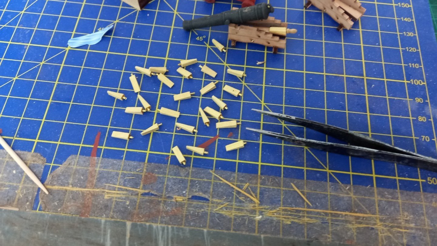
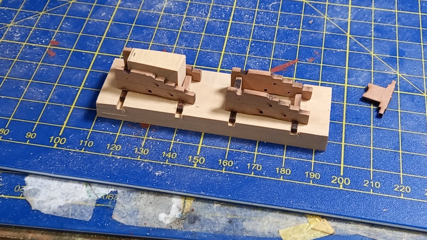
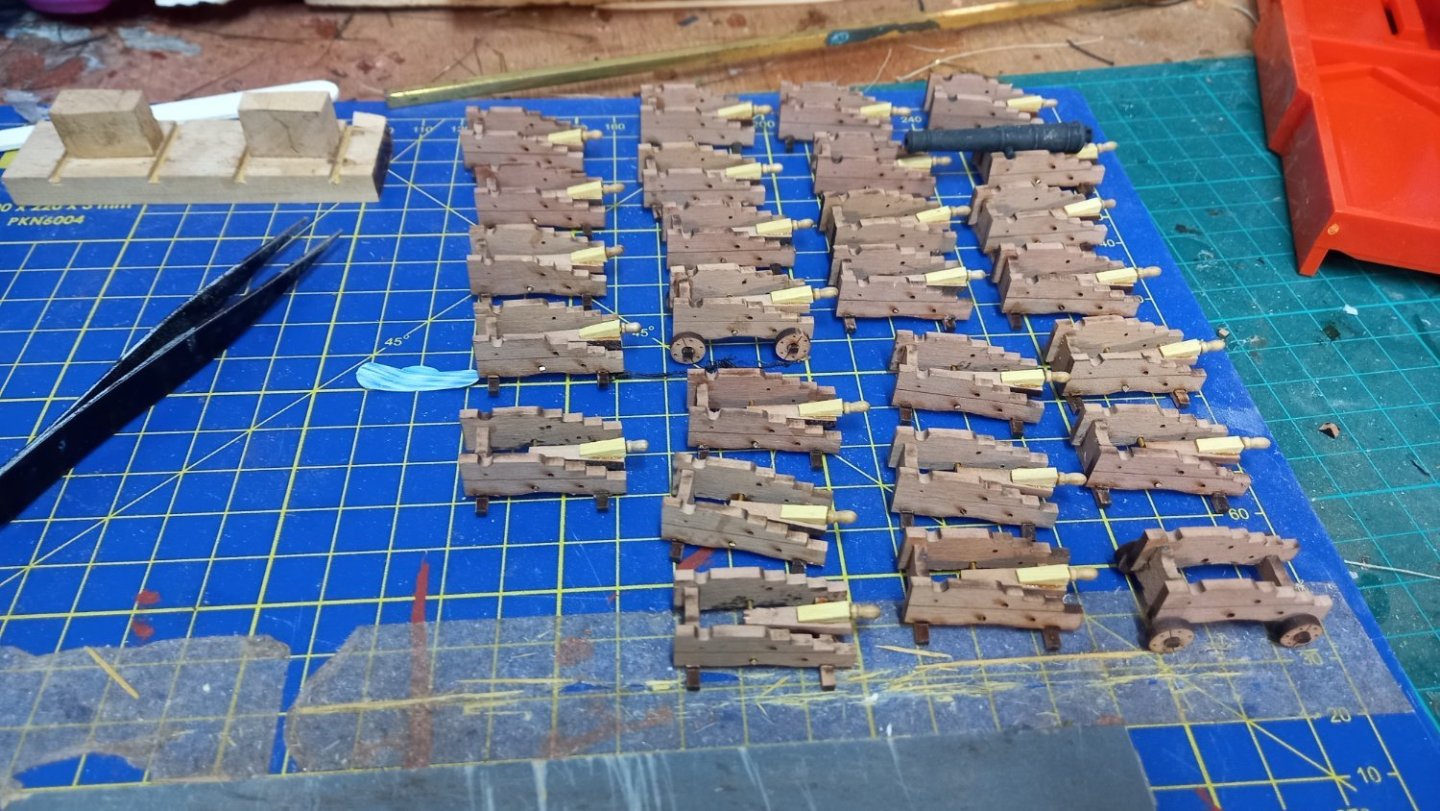
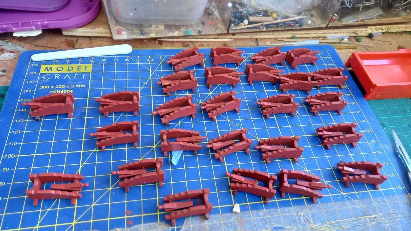
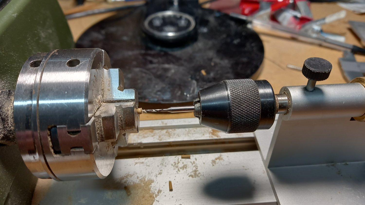
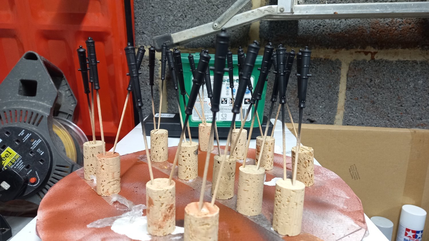
I have made a small jig for assembling the 18Lb gun carriages supplied by Vanguard for the bloomfield cannon. There is still some uncertainty as to whether of not these cannon were actually fitted to the Diana.However as I had previously purchased the Bloomfield cannon I have decided to fit them anyway . Using the jig made life a bit easier during assembly. So will make up another jig for the 9Lb guns and keep them in a safe place for future projects. I have also decided to use the Vanguard pear wood carriages because I think the edges were much more crisp than the supplied Caldercraft walnut carriages .I made the Quoins from of 2.7mm square boxwood and for the handles I used some small 8mm walnut belaying pins which were drilled and pinned with brass1mm brass rod. I have spent the day using my air brush to paint the carriages red orchre and after priming the cannon barrels black Valjeo primer I then finished off with a top coat of Caldercraft Iron black and added flow improver, thinners and retarder. This is the first time I have painted the resin made cannon using an air brush rather than brass cannon and using brass black. I am fairly pleased with the results. I would like to Thank Andrew and Allan amongst others for replying to my question on whether or not to paint the Vanguard gun barrels to try and protect them in the future  There is still a fair amount of work to do on the 18Lb guns. and in the mean time I have also been looking at some of the other deck fittings and mainly the main jeer Bitts and top sail bitts but looking at there positions on the main gun deck and can see that the jeer bitts will not be accesable once the top deck is in place . Thanks to Dunnock who was kind enough to explain how he got around this ,so a big thank you to David ,who helped me on this matter and I can now move forward with and both the main Jeers and the main topsail sheets laniyards can be secured to the same topsail bitts which are only just accesable on the lower gun deck. Hopefully this will be seen better when I eventually get around to doing the rigging. If I ever get there.


-
Thank you everyone for some great answers. As this is the first time i have actually painted my cannon and have always used brass black on brass cannons in the past, I think I will probably go down the primer and matt black and will give my air brush a run out. I have some vallejo black primer which I will use first and I might then do a test piece using Caldercrafts iron black and see what the results are before trying anything else. I have often thought about trying some weathering products, but as yet have not taken the plunge. Perhaps this is the time. Once again I would like to thank everyone who has taken part in this discussion and helped me out. Best regards Dave
-
Thank you Andrew. I will take a look at your cutter build log and see what it's all about. Are washes just diluted acrylic dull black? Thanks you as well Allan. I am not sure what matt clear I'd. Are we just talking about a matt varnish? Thank you for your time and patience. Best regards Dave
-
I have 26 bloomfield cannon 1/64 supplied by Vanguard and are already black in colour and look quite realistic and great detail. I am wondering if these require painting or perhaps a coat of matt varnish to protect the surface would be enough. I think these are made from resin and are produced on a 3 D printer but I could of course be incorrect. Please advise what others have done when using these cannon for their ships .Thank you. Best regards Dave.
-
I am currently in the process of fitting the above but I am somewhat confused as to the design of these and why they are fitted to the lower gun deck and how are the ropes accessible.? First off, are the bitt pins fitted with sheaves and whether or not the cross beam would be fitted with any belaying pins? Although I do not totally understand the drawings of the AOTS belaying plan I believe that that they do carry both sheaves on both the main top sail bitts (2) and (1) on the jeer bitts together with 2 belaying pins on the Main top sail bitts.. Whats confusing is that according to the Caldercraft instructions the Topsail haliyard and the main jeers ropes go to the fore brace bitts which is on the top deck which are accessible.If this is the case why have the bitts under the top deck? So what am I missing ? Best regards Dave
-
- 2
-

-
Excellent aproach and great looking coamings and gratings. I see that you built the coamings around the gratings rather than fitting the gratings into the coamings and think this might be a better aproach than the way I have just done them. I also think you cut the holes into the gratings before fitting them a better idea as I have left them until ready to recieve the anchor ropes . I wish I had seen this post earlier. As usual great workmanship from you Andrew and overall so far a really splendid look ship.
-
Thanks Mark for the tip regarding taking off a bit of material off the stove feet if need be, something I had not thought of. Thank you also for your continued support. Best regards Dave
-
Completed fore and aft riding bitts. Pinned the back beam as well as glued using PVA and very fine pins.Thinking of using ply wood for the stove floor tiles. Unsure of the thickness which will depend upon the height of the chimney in relation to the deck above. I am thinking of framing this piece of wood and might score the wood to look like tiles. Unsure of the thickness of wood required for this as I have used the Brodie stove supplied by Vanguard which is an upgrade on the Caldercraft supplied parts and may need to adjust this hieght to get the right height above the upper deck. Any ideas on the correct thickness of this flooring would be greatly appreciated. I have primed the stove with white primer as I have no black primer at hand and will air brush this when I have attched the various brass parts I have replaced the grating for the origonal light colour which is what i have hoped for and sealed them using Liberon sand & sealer which worked better than shellac or varnish as these just seemed to darken them more than I would have liked. According the Caldercraft instructions next up is assembing the 18Lb gun carrages and associated fittings but I might deviate from this somewhat and inbetween and finish off some more gun deck fittings such as capstan, bilge pumps and binicle and manger etc cl
.thumb.jpg.0e1b640cd8749109867303490e2f0d4e.jpg)
-
Fantastic scroll work and fine detail which shows a very high standard of workmanship. I also agree with Mugje the colours are very pleasing to the eye.
-
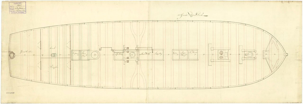
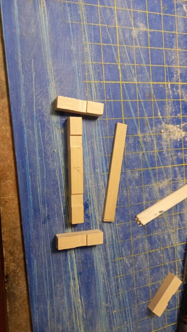
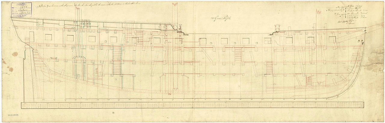
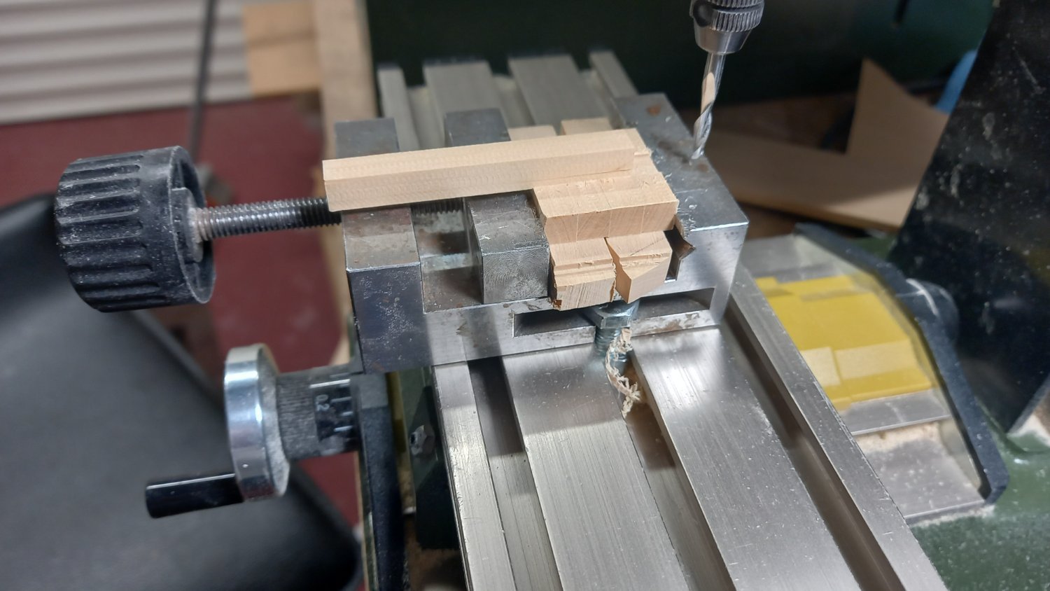
After further consideration of the Riding bitts and comparing the AOTS drawings and those supplied by RMG there are clearly a few differences. The first two drawings are from the MRG site and the last drawing is a copy of the drawing from AOTS Diana. Looking at the side profile drawing( second drawing down, the cross beams and pins of both fore and aft riding bits look similar in size ( cross section). However the AOTS Diana drawing clearly shows that the forward riding bits are smaller than the aft ones.(cross section). Unfortunately when looking at the first drawing from MRG this does not confirm the above either way. At least I can't tell either way. The cross beam looks to be the same (cross section) but are not as wide and the fore standard is shorter than the aft one. Therefore my conclusion is that . Perhaps the both fore and aft bits would be identical had they not come up agains the fore jeer bitts. I am still not convinced either way which is correct and can see from a few Diana builds that they have made the fore riding bits smaller so wonder if I am wrong in thinking the sections are the same for both the fore and aft riding bits. Unfortunately Caldercraft have decided to only supply one set of riding bitts and even these look to be too small in section . I will start making the aft riding bitts from 6mm boxwood sheet and perhaps by the time I am ready to move onto tmaking the fore riding bitts, somone can come up with what is the general practice. For the record the book' The Construction and fitting of the sailing Man Of War 1650~1850' by Peter Goodwin. States that the construction of the riding biits are the same but unfortunately does not mention the sizes.
.jpg.ab627d202cbf5a4ff04461ea18c6c7a0.jpg)
.thumb.jpg.e4c751b8e9b29590a7806b9ddfa011ff.jpg)

.thumb.jpg.51158fa57992732190890c8c7ce7789e.jpg)
-
Thank you for your quick replies and interesting to see that the tiles could have been added after hand over . Does this mean that both tiles and the metal sheeting could be fitted at the same time. I will take another look and see what other modelllers have come up with and whether or not any have applied both tiles and metal sheet. One more question if I may regarding the fllu of a brodie stove. How was this sealed in the area where it passed through the deck above? Best regards Dave
-
I understand this is more for the scratch build enthusiast but thought it might be helpful to any ship modeller who wishes to learn more. Please share you views if there is any proud owners of this book. Thank you for reading . Best regards dave
-
- 1
-
-
If I may, I would also like you to compare the two drawings where I have highlighted the floor underneath the Brodie stove where there looks to be an extra bottom plate or layer of some sort. I appreciate there is a layer of tiles underneath the stove but this would not extend between the ridiing bits and the other forward bitts for the Jeers. This extra layer can be seen on the MRG drawing as a dotted line. I do not understand what this is for. Any help in any way would be very grateful and I appreciate your past and present patience. Best regards Dave
.thumb.jpg.2189d177f9c2b7c912645686e4e794ca.jpg)
-
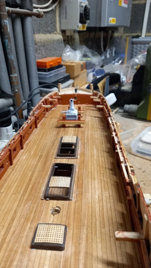
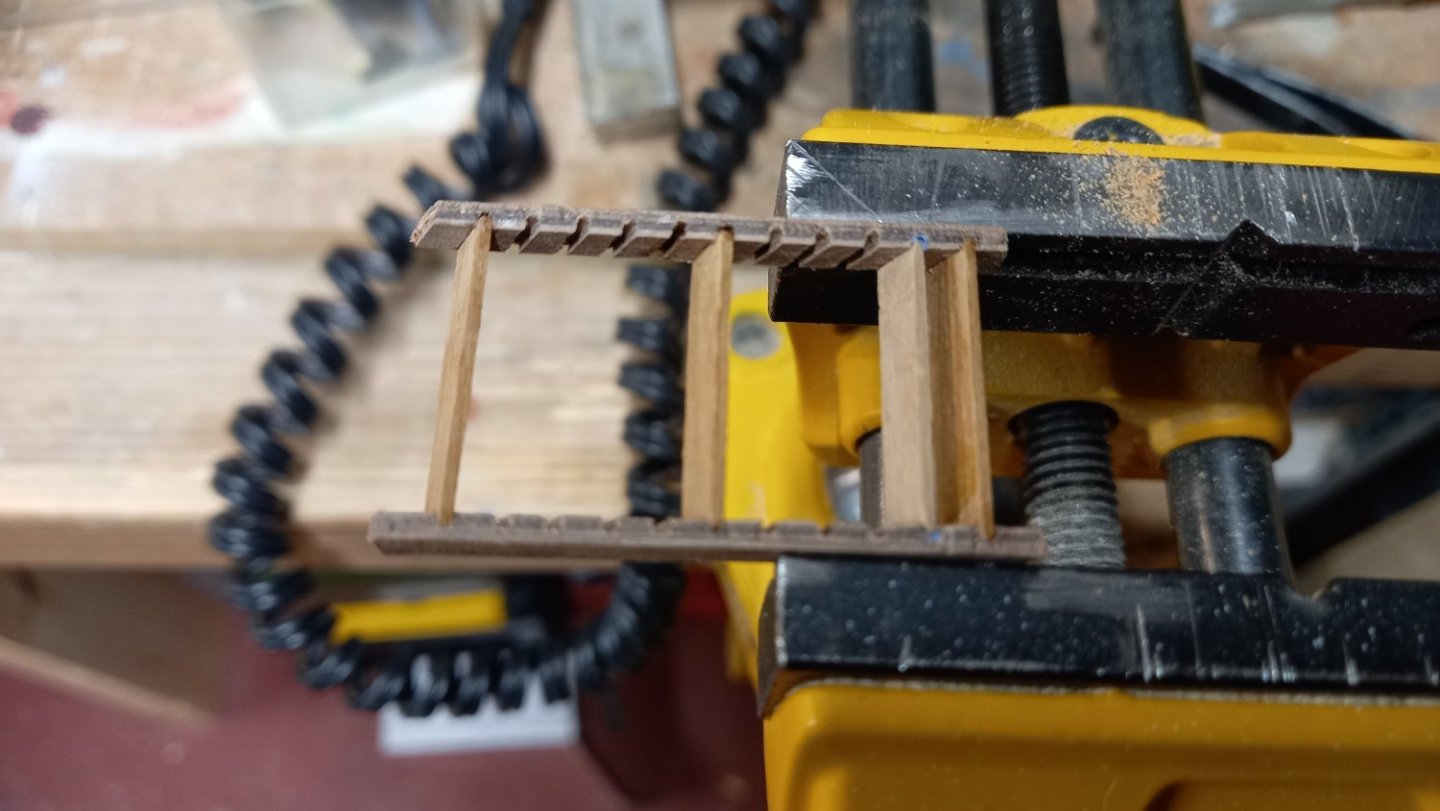
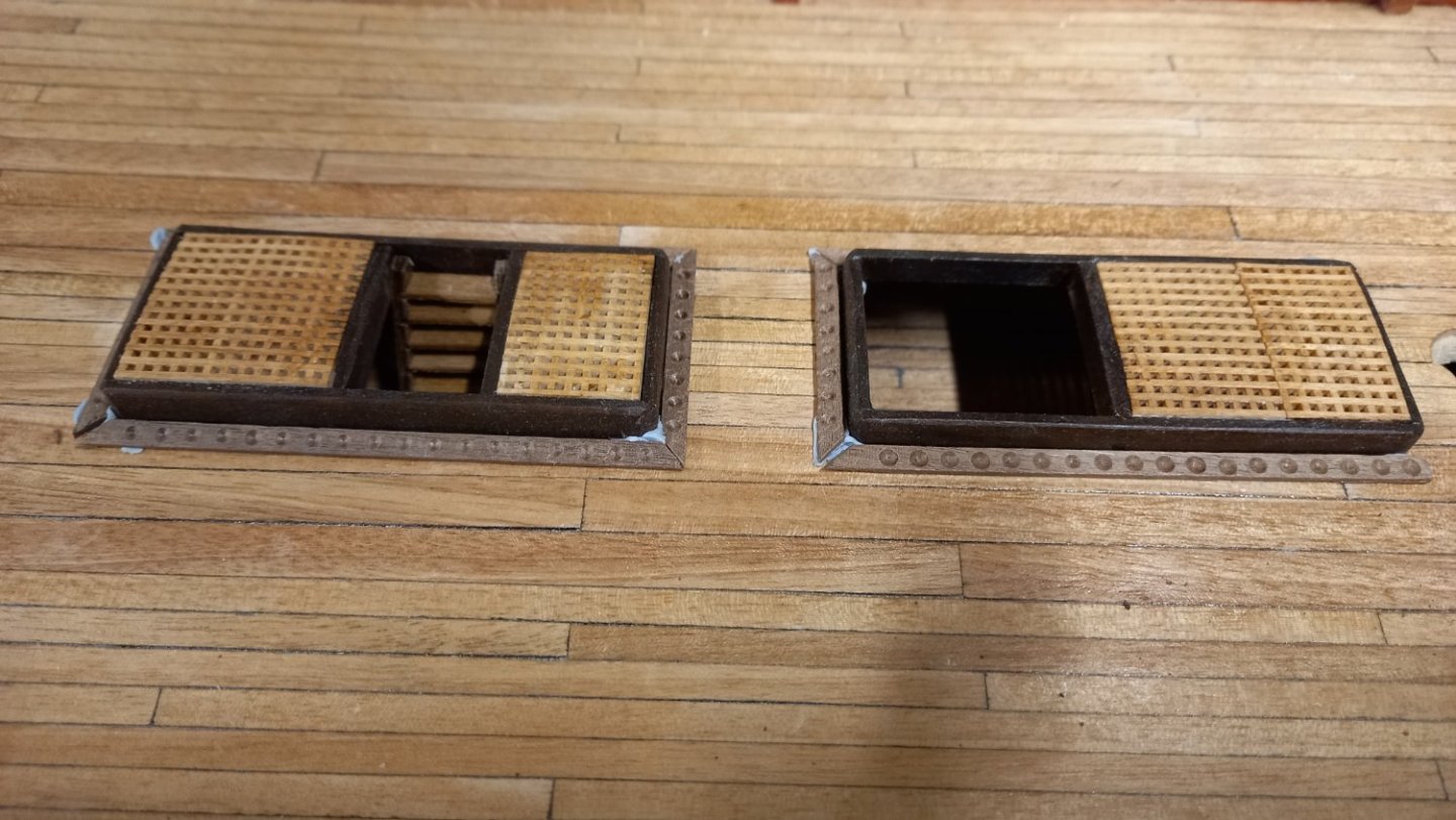
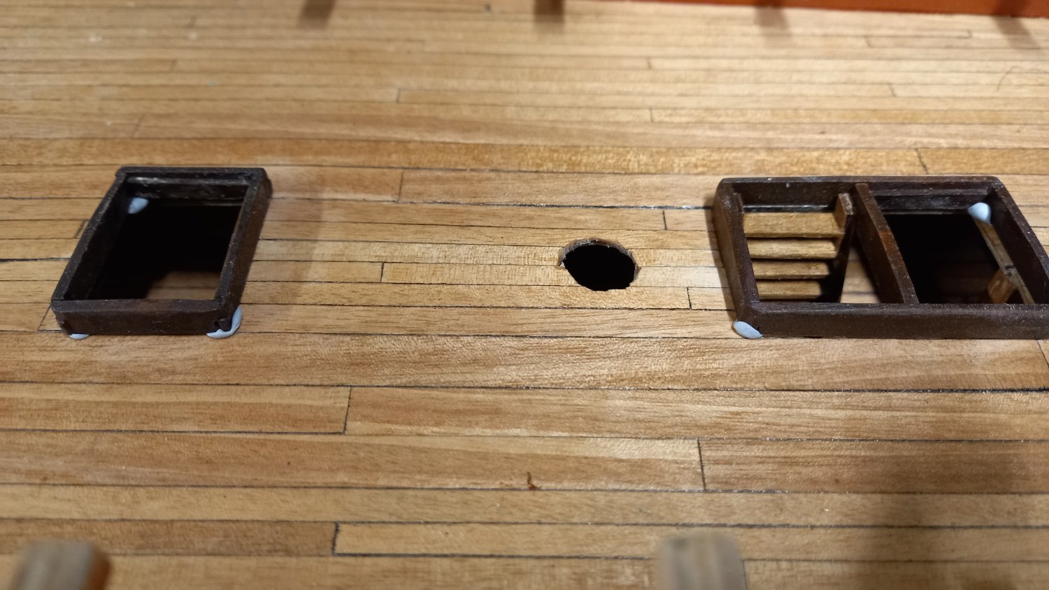
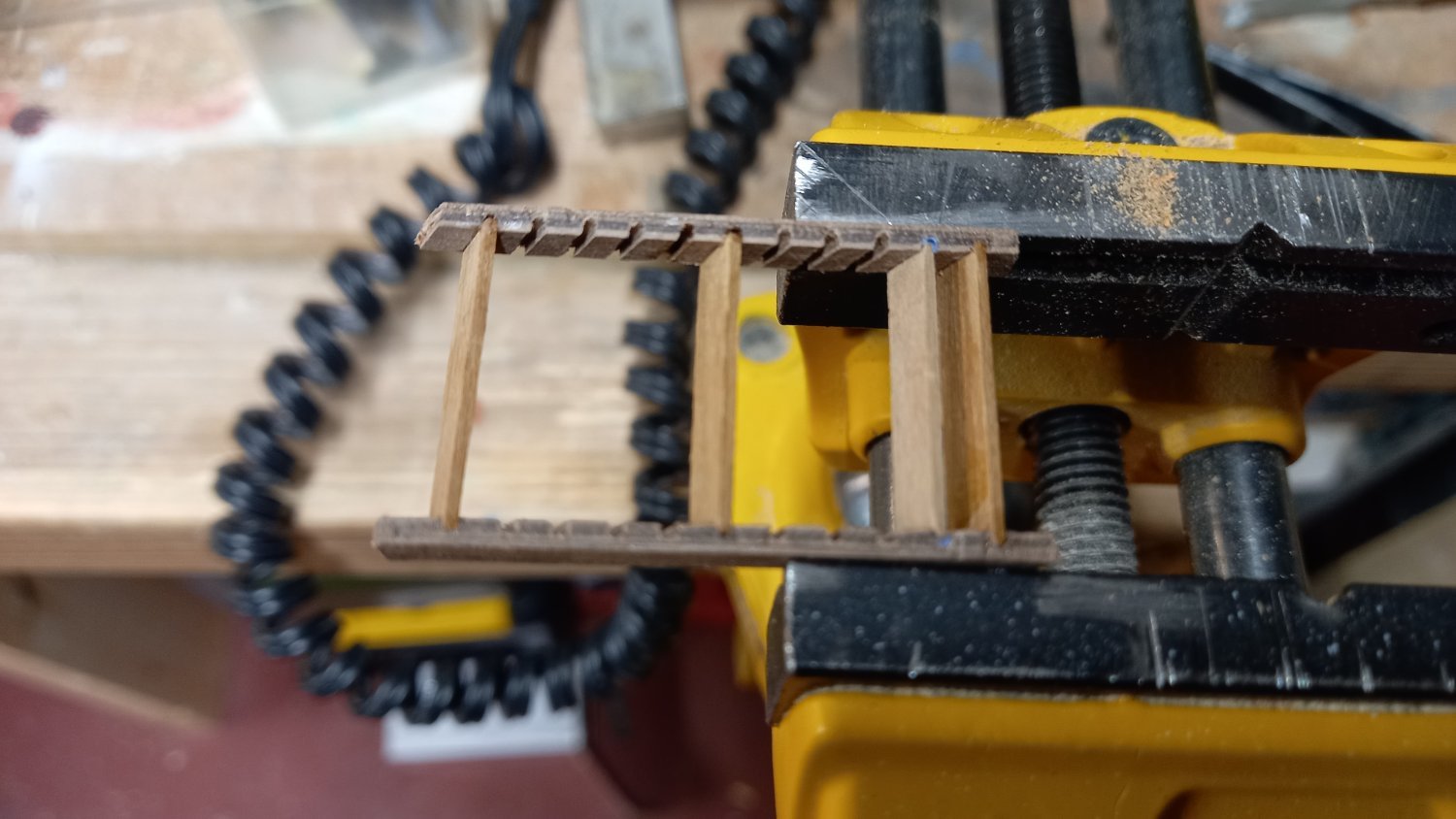
Hatch coamings ,gratings and ladders Moving onto the above and other deck fittings. I used boxwood for the hatch coaminngs and used the supplied gratings. I stained the coamings dark using a mahogony stain to give some contrast with the gratings then sealed them using a varnish , however this run into the graings and darkened them somewhat so will probably replace these at a later date. I also used the kit supplied parts for the step runners and 1x 4 mm walnut for the actual steps then used walnut for the shot garlands and using a forming cutter for the recesses.I distroyed the largest of the steps when trying to fit a middle runner so will need to make a new one. I intend to cut the middle runner on my Proxxon Fet bench saw using a 1.1mm wide cutting disc and hopefully this will make it easier to fit. Clamping the steps into the runners. temporarily positioned coamings with shot garlands and showing gratings and steps coamings without gratings and another set of steps Whilst waiting for some more gratings to come from caldercraft and some more side runners for the steps, I have been looking at the Riding Bitts. I intend to use boxwood for these and take the sizes from the AOTS book. Looking at some of the other builds of these I can see a number of builders have painted the cross beam on the forward half only and can only wonder why. Other than it looks rather grand is there any other reason for this perhaps the paint would just wear off due to the anchor ropes rubbing on the bits but then why not leave the paint off altogether. Any thoughts on this would be appreciated.

-
Those Liberon products look really impressive Andew. She looks absolutely amazing . Using these products is definitely I might try on my next model.
-
Sorry to hear that and I look forward to your return to modelling and of course more importantly your wifes return to good health. I wish you both a Merry Christmas and a better new year. Good luck. Dave
-
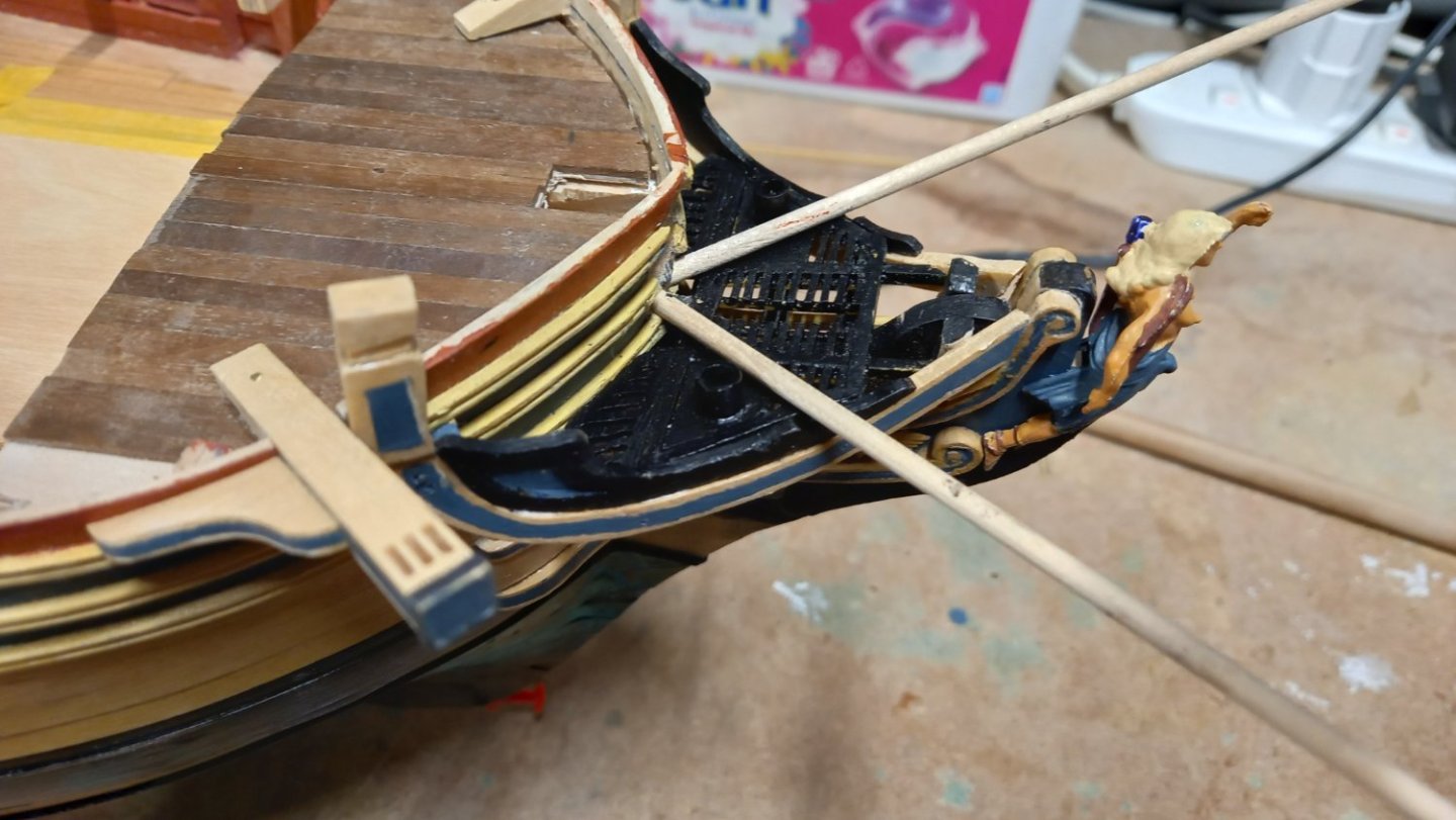
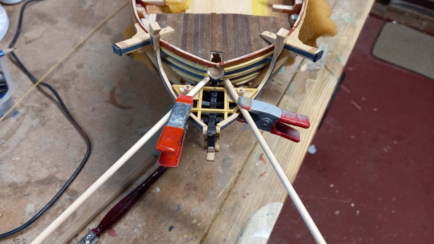
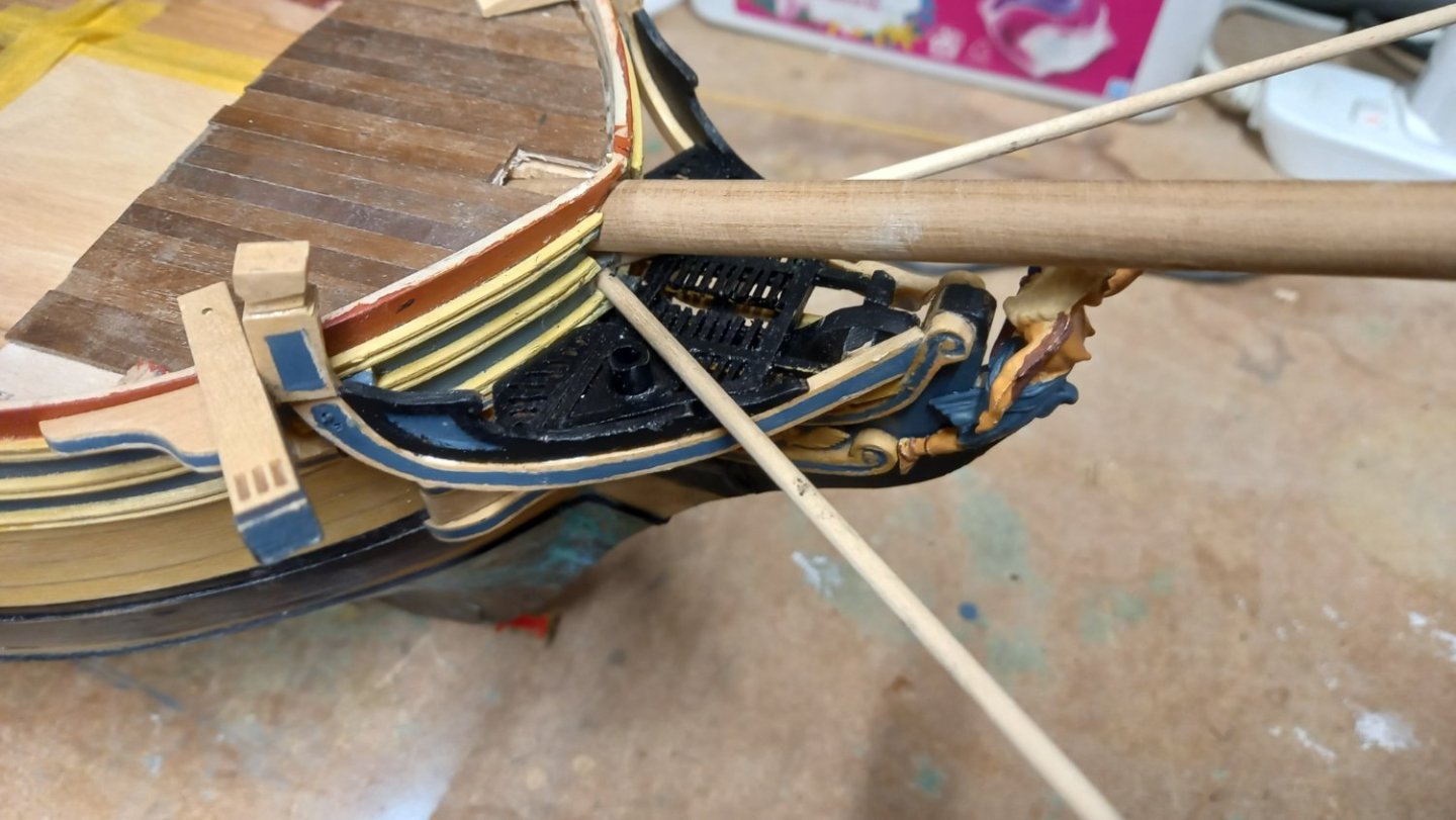
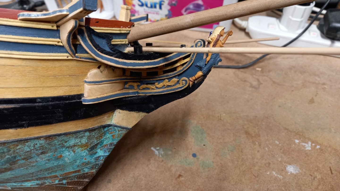
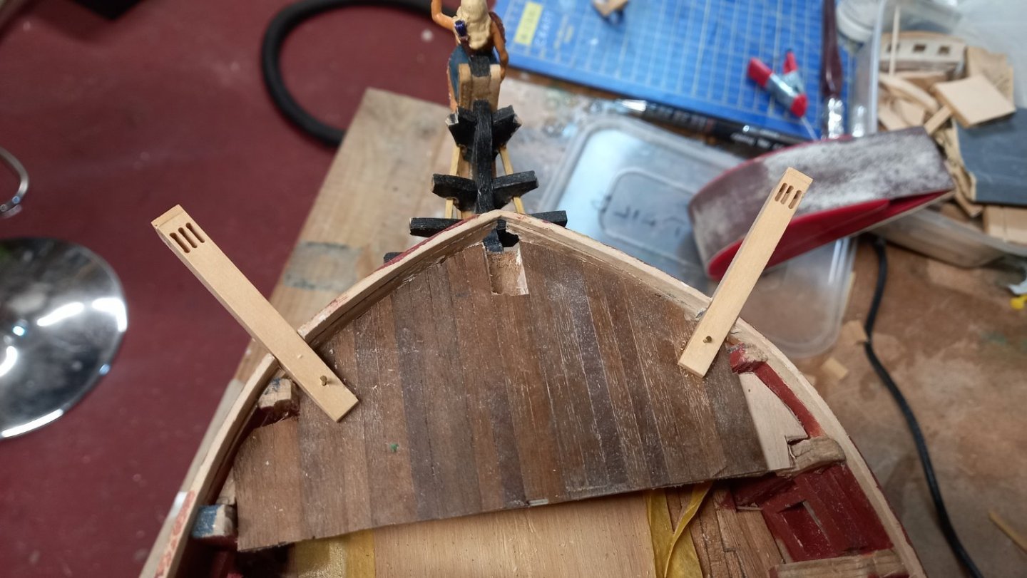
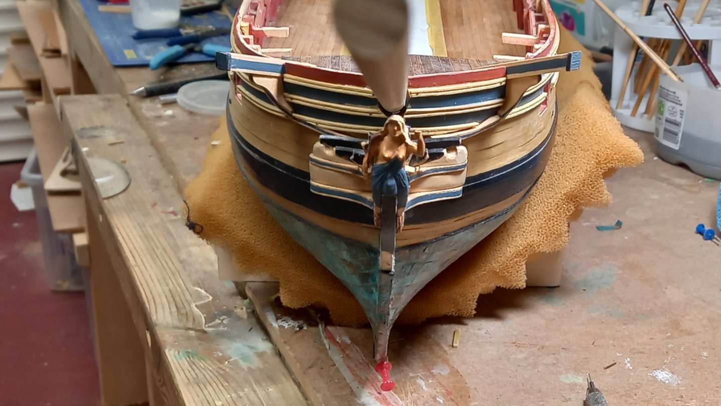
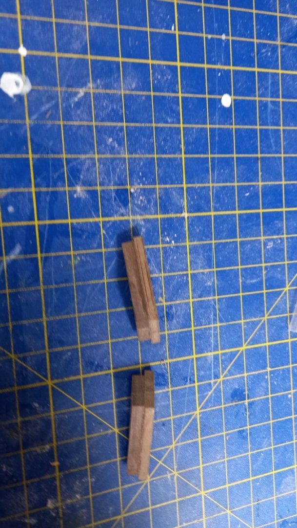
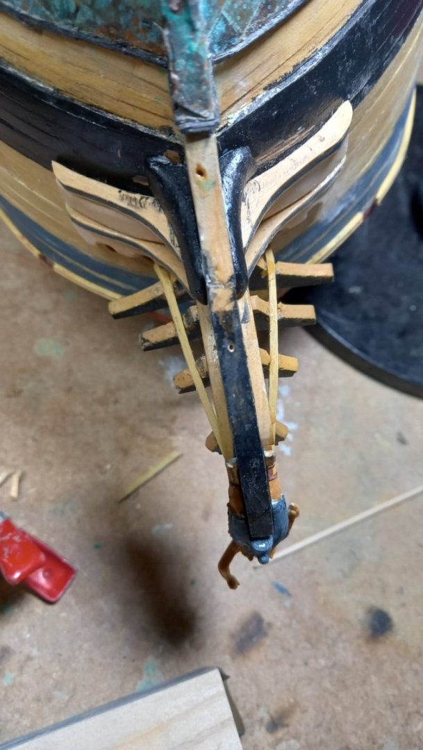
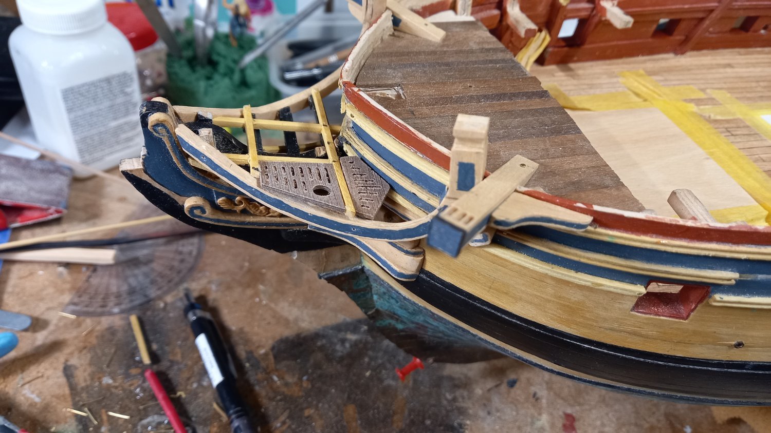
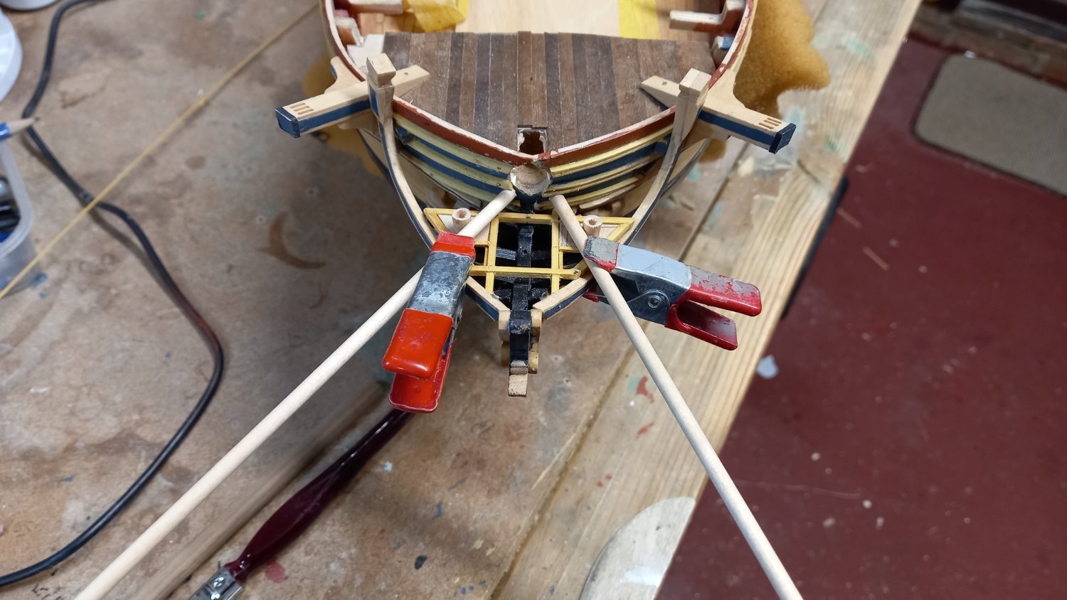
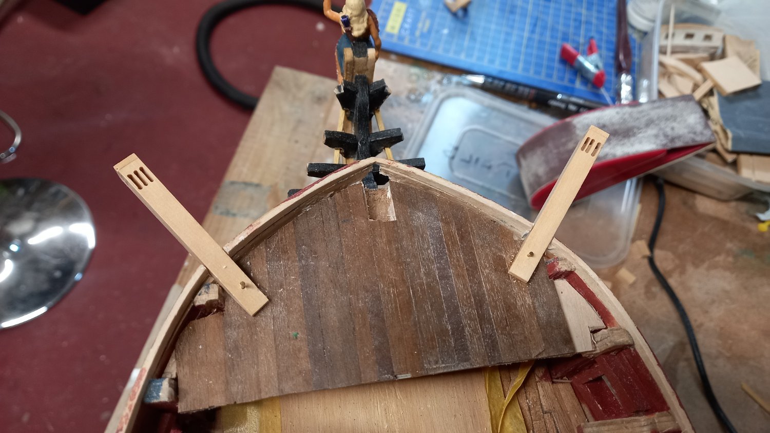
A 5 mm lime dowel was used for the seats of ease and drilled with a 3.5 mm drill. I did not use the supplied parts for the grating as the slots were very fine but used the origonal section for the out size dimensions and used 2.7 square boxwood sanded down to 2mm square for the frame and 1mm square boxwood for the ledges and the same for the actual grating pieces. Although the finished piece is different than the actual Caldercraft plans but apart from the paint work which could have been better I am fairly happy with my first attempt manufacturing my own parts out of boxwood and scratch building this part of the build. Lining up port & stbd recesses for Boomkins were slightly out so will need to correct this at some later stage. I am really glad to have completed this part of the build as this is the first time I have attempted to make my own head rails and other parts out of boxwood. I have made a number of mistakes and I have had to compromise with a the grating and seats of ease etc but on the whole I think it has been an improvement on the supplied kit parts and looks reasonable from a normal viewing distance. Hopefully as I continue with the build I will find the next bit easier going.


-
Another big thank you to dunnock,DavidEN and Beef Wellington for helping me with their Diana build logs and getting me through a number of issues with the head rail assembly. Once again I used boxwood for the various parts including the catheads and cat head supporters and cathead knee. I temporarily made up a section of decking and using 1mm walnut and planked this small section to ensure I had the correct positions of the catheads when making the cathead supports and also enabled me to fit the Ekeing and lower rail too. I used a 1mm milling cutter for the cat head reeve slots rather than using thin strips as depict in the Caldercraft plans. I then touched the paint work between the sheer rails and replaced the sheer rails and when the glue dried I removed the necessary sections from the sheer rails to fit the Cat head supporters. Next up is the Main and false rails the kit parts come as one piece but don,t think the main rail will make a good job so will make this out of boxwood. I will then attempt to modify the combined Main and false rail by removing the head rail and discarding it. AS the false rail is painted black , I think this walnut section can be used. Phew ! Almost complete. It has taken me almost a month of work on the head section alone to get thus far and was definately the biggest challenge so far. Just the grating pieces to make out of boxwood , seat of ease and to finish off some fittings on the catheads. The combined cathead together with the knee and supporter are not yet glued into position as I will need to remove these to gain access to remove the temporary section of decking and fit the upper deck at a much later stage.

.thumb.jpg.d017f700cd1b8bd5ba8238a330a2b103.jpg)
.thumb.jpg.9f571de59287afce2fc64f9e9e55c89b.jpg)
.thumb.jpg.79354df53a86117665d43f0dbc3b1e13.jpg)

-
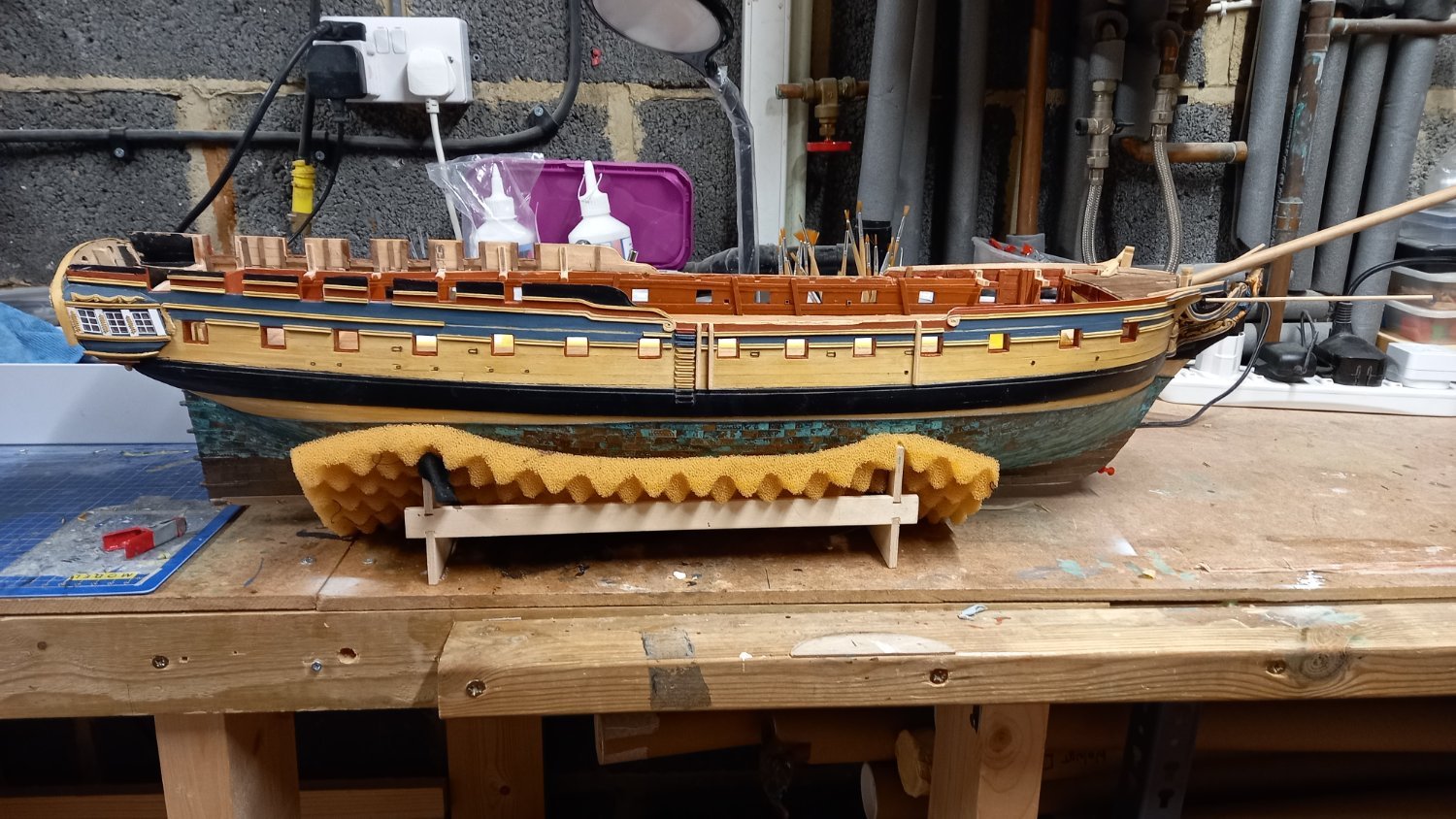
She looks absolutely fantastic in her new home and what a feature to have in any room, although it will need to be quite large. Haha You must be very proud so take a bow David. I will definitely be looking at alternatives to acrylic as although it is lightweight it is also very expensive.
- 310 replies
-
- 3
-
-
- Diana
- Caldercraft
- (and 1 more)
-
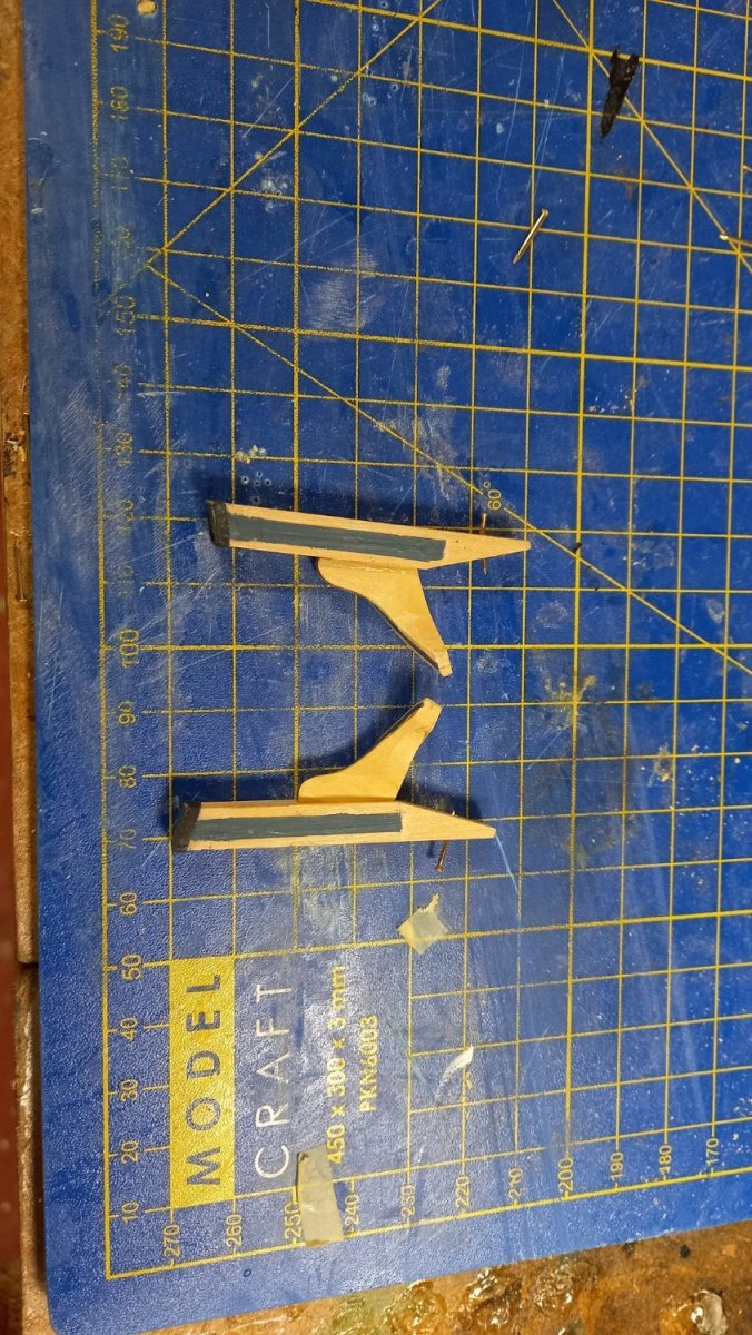
Continuing with middle rail and cant wash, I used 1.5mm square boxwood for the middle rail. I also managed to turn the supplied upper and lower walnut cheeks into the wash cants and taking the approximate sizes from the AOTS Diana book. Moving onto the Cat head cat head supporter and Ekeing and again i think I will make these from boxwood.Acording to the Caldercraft drawing there is quite large differences in the setting angles of the cat heads than the angles depict in the 'The construction and fitting of the sailing man of war 1650 to 1850' by Peter Goodwin who has 45 deg fom the center line and 15 to 20 deg from the horizontal. The Caldercraft and AOTS has these at 55 deg and 20 deg respectively. I think 20 degs should be ok but wonder if 15 deg would be better. I however think that 55 deg should be ok and wonder if I changed this would give me problems with stowing the anchors at a later date. Any thoughts on this would be appreciated.

-
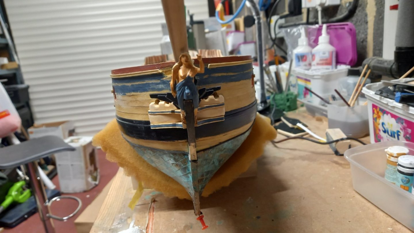
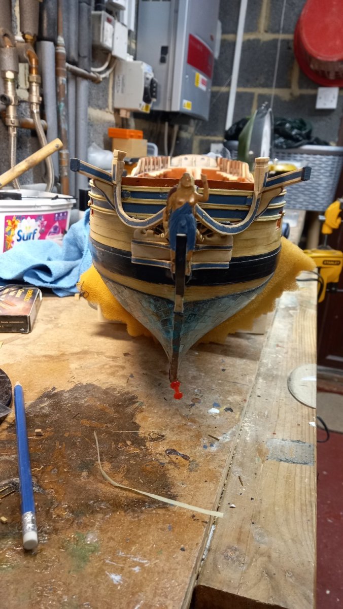
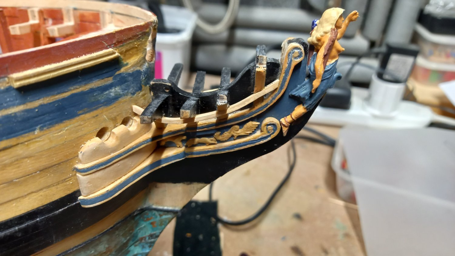
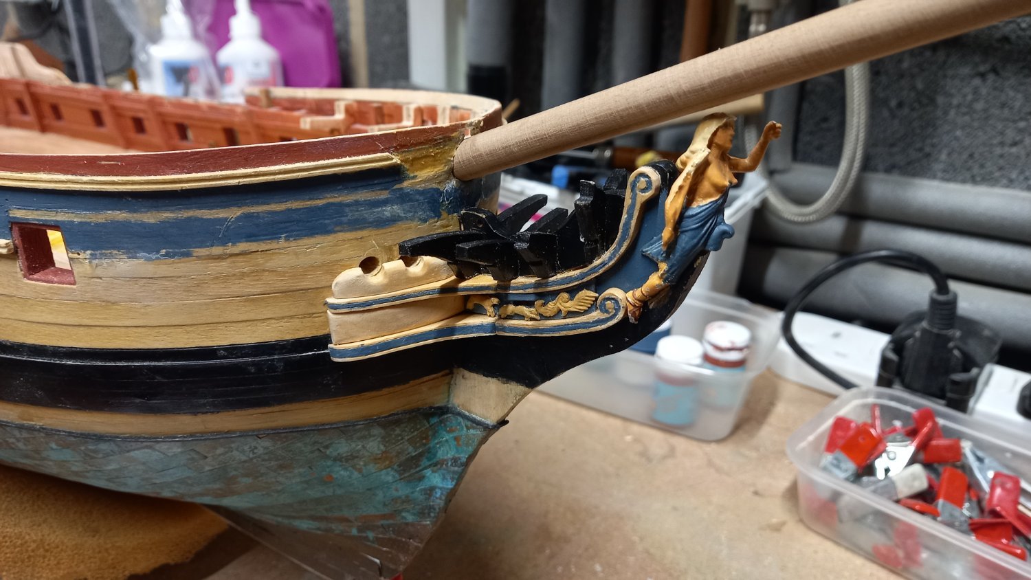
A little progress with regards the head section and rails. I managed to get all three of the animals onto the sides but not in the same order as the Caldercraft drawing as I had to place the thinner dog in the middle so that it would fit under the gammoning hole. Although most of the parts are made from boxwood , I did however use the supplied four timber heads.. I have glued these into position as per instructions but also pinned them to give extra strength to the srem post which had previously broken off and thought it might need a bit of added strength. Hopefully I will not regret this if the timber head sections require replacing for whatever reason. Unfortunately the decorative side pieces didn't turn out as well as I hoped, I didn't have much joy using the yellow Tamiya masking tape after sealing the wood with shellac and after several attempts I eventually ended up painting them by free hand . The section of upper sheer rails still require replacing but think I can leave this until the head section is complete. I also need to touch up the paint work on the figure head and other sections of the bow. UnUnfortunateU

.thumb.jpg.48e47fd0ee691f77b93d238da6039428.jpg)
-
Some really good tips coming in. Great thread.
-
Masking tape for curves .
DaveBaxt replied to LEGION 12's topic in Painting, finishing and weathering products and techniques
Thank you for your quick response and for clearing that up for me. Best regards Dave


.jpg.5364b49bb60de8c3f3640b1cd0680c80.jpg)

.jpg.4e536f90c5829947c532cf052fb9f241.jpg)
.jpg.f9ab323af8555edf9075210d14442831.jpg)

.jpg.717cd3982cbf173383fea8a5f7a6c735.jpg)


.jpg.068219f24f3b2901a72c6baab1774db1.jpg)
.jpg.8884bc70e62edac2bc5e3a845fb36ffd.jpg)
.jpg.cb08dfa245ae424de6b18f35d45b1be7.jpg)


.jpg.7783a4237665a2ef977e21558b6448ef.jpg)
