
HOLIDAY DONATION DRIVE - SUPPORT MSW - DO YOUR PART TO KEEP THIS GREAT FORUM GOING! (Only 24 donations so far out of 49,000 members - C'mon guys!)
×


Dan Vadas
-
Posts
3,261 -
Joined
-
Last visited
Content Type
Profiles
Forums
Gallery
Events
Everything posted by Dan Vadas
-
Thanks for all the comments guys, much appreciated . I won't be buying another GPM after doing this one Chris. I'm not at all happy with anything in the kit. From now on it'll be Halinski, although the Paper Shipwright Cerberus wasn't too bad - the only problems I had with that one were mostly my lack of experience with Card (it WAS a learning project after all ) and the quality of the printing which was due to my getting it done commercially instead of buying the printed kit from the manufacturer. I've made and fitted the three Aft Rangefinders and the aft radar, along with their support platforms. Construction of these was detailed on the fore units, so I won't repeat myself. All turned out well : Danny
.thumb.JPG.aff6dd41cb3a372c20ad793c2a1381c7.JPG)
.thumb.JPG.c018a195167c20d94f7a0f11e1716163.JPG)
.thumb.JPG.999b9cc6e10a802e1d6f3dcb7b27d3b9.JPG)
.thumb.JPG.ef6aabf6a823b2658068436aae9ac9bd.JPG)
.thumb.JPG.56b9f58fb529c603bf3a5f2157a337d0.JPG)
.thumb.JPG.3b30d32e2b29c4504f9c2a9c754f9455.JPG)
.thumb.JPG.412f1511d898ad37bd05923742e267f5.JPG)
.thumb.JPG.ff4fdde05a538b45aaa3e778cc20343e.JPG)
- 524 replies
-
- 17
-

-
Thanks for that Grant . I thought it might be time I posted some Progress pics. The fore and aft superstructures haven't been fixed to the main deck yet as I still have work to do on both of them and it's easier off the hull : Danny
.thumb.JPG.6c8f1929e92d318d11e979664e52ae77.JPG)
.thumb.JPG.1852590501b39e1afc50632e5cb61f10.JPG)
.thumb.JPG.f6ebf42310b8e278f4f1bbdc5bd0502b.JPG)
.thumb.JPG.8d3062eb3b32084b2b04443ef16186bf.JPG)
.thumb.JPG.205723793bc8b309f41acb6c793e304f.JPG)
- 524 replies
-
- 25
-
-
Thanks again Jan and Paul . When I went to fit the hangar to the 1st deck I discovered a big mistake. Once again the inadequate instructions led me down the garden path. I'd fitted the two centre boats to the racks as per the drawing, but they were a mile out of position. There was no way that the hangar would fit against the deck behind it, as the boats hit the railing. In fact they would have been almost all the way into the range finder on that deck : Nothing else I could do but try and remove the two boats and move them forward the required distance. This wasn't going to be easy, but I managed to cut them both free with almost no damage to either the boats or the racks : A bit of paint, some small modifications to the racks, and all was well . The outer boats are a little too far back as well, but they don't interfere with anything else so I'm not going to push my luck trying to move them : Danny
.thumb.JPG.12b0624ce65f7c2ffbd0dd7e39094c42.JPG)
.thumb.JPG.31f992cc882cc014fa0987890ab0d22d.JPG)
.thumb.JPG.988937c90155885dfc171fda8927d7ce.JPG)
.thumb.JPG.f050c58ce416dc130689cbf2cd8e7225.JPG)
.thumb.JPG.a7d7a1a94082e524ed45d8a9ffe74b2c.JPG)
.thumb.JPG.81713bba08779c41a193f4f0e3fe545f.JPG)
- 524 replies
-
- 21
-
-
Thanks for the Likes guys . A few tips on how I fit PE Railings on a slightly tricky platform. The first pic shows one strip of railing already fitted, and I've drilled and fitted the first post (which is actually the 3rd one from the join). Note that I haven't worried about joining the two strips together yet. The MDF blocks support the loose end roughly to the right height : I fitted the other two stanchions in the straight section before moving to the bend. To shape the bend I use a piece of plastic tube to support the inside of the rail and gradually push the rail in, moving the tubing as I go (the MDF block is taking the place of my finger while I took the pic). I do one stanchion at a time, using the MDF block to hold the stanchion right on the edge of the platform so that I can position it for drilling : The drill I use is one made for drilling PC boards. It's made of tungsten, and is 0.4mm in diameter. Each drill has a plastic collar attached, different colours for each size to make identification easy. When using them without a pin-vise I can use the collar to turn the drill with my fingers. For this job the pin-vise is a better option : Once the hole has been drilled I use a pair of narrow-jawed tweezers to locate the stanchion in the hole : I use a piece of strip wood to determine the height above the deck of the lower rail before applying a droplet of CA glue using a needle with the end of the eye ground off : The finished platform. A PE ladder has been fitted into the gap between the strips of railing : Danny
.thumb.JPG.baf9aa42a791641f1835c6857483187b.JPG)
.thumb.JPG.9401d28a85fb4c93280d247491d31930.JPG)
.thumb.JPG.d7c5b5f427b32ca801653e91c51b2f43.JPG)
.thumb.JPG.9d011a98f3a521be5a015461d7db43d2.JPG)
.thumb.JPG.0323832809c709da0e38f76394ea873a.JPG)
.thumb.JPG.9117adc5d92bbffe5778d02299fbfe43.JPG)
.thumb.JPG.40b18649bf9db0edd52248508d24b6f3.JPG)
.thumb.JPG.6427026846fdcca4218228ac67161c63.JPG)
- 524 replies
-
- 20
-
-
Thanks for the tip Jan. I've finished the 3rd deck. The pieces of railing hanging in mid-air will be attached to the structure along-side. Lots of louvres : Danny
.thumb.JPG.7316d2f798c66515a25e1562722e79d8.JPG)
.thumb.JPG.3679efdba7092c36d4544c1fc1cba8e8.JPG)
- 524 replies
-
- 14
-
-
Thanks Henry. Yes I was wondering about that, it makes sense . Thank you too OC. Danny
-
Thanks again Popeye. Construction of the Aft 3rd Deck is similar to all the others. The Bulwark in the middle of it took some fun folding : I started fitting it by gluing on the shallow curved central section : To get the tight corners to sit flush I used a couple of heavy brass weights : Supporting the two end sections so they were in line with each other : The bulwark fitted and edge painted : Danny
.thumb.JPG.fd65972426041b5c63fd55d799ebeb5e.JPG)
.thumb.JPG.cf4f182e192d4d6e03402a86328a3627.JPG)
.thumb.JPG.778357ad5938441f9cc3710fe35c01d3.JPG)
.thumb.JPG.9ac5ed5eed23ce556f249d0bf08e2adf.JPG)
.thumb.JPG.5e9c53c7c04150ad75d3afe2b6fa487d.JPG)
- 524 replies
-
- 17
-
-
Because I find using CA a lot quicker, easier and almost as strong - certainly strong enough for this job. BTW - I would use silver solder, not soft, using a pen torch if I thought the job needed it (e.g. if I wanted to keep the parts brass instead of painting). Danny
-
Thanks CDW and Reg (welcome to the build Reg ). That still doesn't mean I don't make mistakes though CDW. Something to do with being "directionally dyslexic" . I also discovered that I'd fitted the spars on the other mast onto the wrong side, so both of them were cut off and re-fitted. Once again it's very difficult to see my mistake. There is a longitudinal spar on the main mast, which also has a horizontal one attached as well as a couple of braces. I made this unit from 0.8mm and 0.4mm wire, CA glued together. I've now permanently attached the mast into position : Danny
.thumb.JPG.c2874f15163169349459c59f74c5c038.JPG)
.thumb.JPG.0d1f8a0031d6b53e7d689e0e97fefbb3.JPG)
.thumb.JPG.0c4e9b910e5c0a6f7febb3e26999a3d3.JPG)
- 524 replies
-
- 15
-
-
Jeff, they are a lot easier to sand before they are fitted to the deck. Danny
-
Thanks very much Nils and Popeye . After looking at the pics of the main mast I got the feeling that I'd used the wrong spar for the longer lower one. Sure enough, wrong part number . I carefully removed the one fitted using a new scalpel blade to cut through the CA glue. It came off with no more damage than a bit of lost paint : I fitted the footrail to the right spar and reattached it : That looks a lot more like it : Danny
.thumb.JPG.929522c3ede0349790d3976df8637e01.JPG)
.thumb.JPG.6ca4bb787cd5911ac26fcf241786f261.JPG)
.thumb.JPG.1d728512489954aa8bd698e7a58d5f21.JPG)
.thumb.JPG.0b7a2441f6413e87f105b803d7ce5c03.JPG)
.thumb.JPG.582edade405dc0c9741ad248d5be8ee0.JPG)
- 524 replies
-
- 11
-
-
The main mast is all done. It's still loose at the moment, I'll fit it properly later on to avoid damage : Danny
.thumb.JPG.81528b44d3cb2979861c44db047882ac.JPG)
.thumb.JPG.62abe62ab5e00c217b21a66eec22e174.JPG)
.thumb.JPG.47d31359404f63e8039784539f8a7c55.JPG)
.thumb.JPG.fdc19d41b0ae3c9b25ed6a3dc4d22145.JPG)
.thumb.JPG.e14b0837493d730255dd0aa4bbdf5263.JPG)
.thumb.JPG.a40ec4f5ba3467403d065a7b7b72a920.JPG)
- 524 replies
-
- 16
-
-
Here's what I was talking about earlier - the mast platform temporarily fitted over the launches. Not much room to get the middle ones in and out : Danny

- 524 replies
-
- 16
-
-
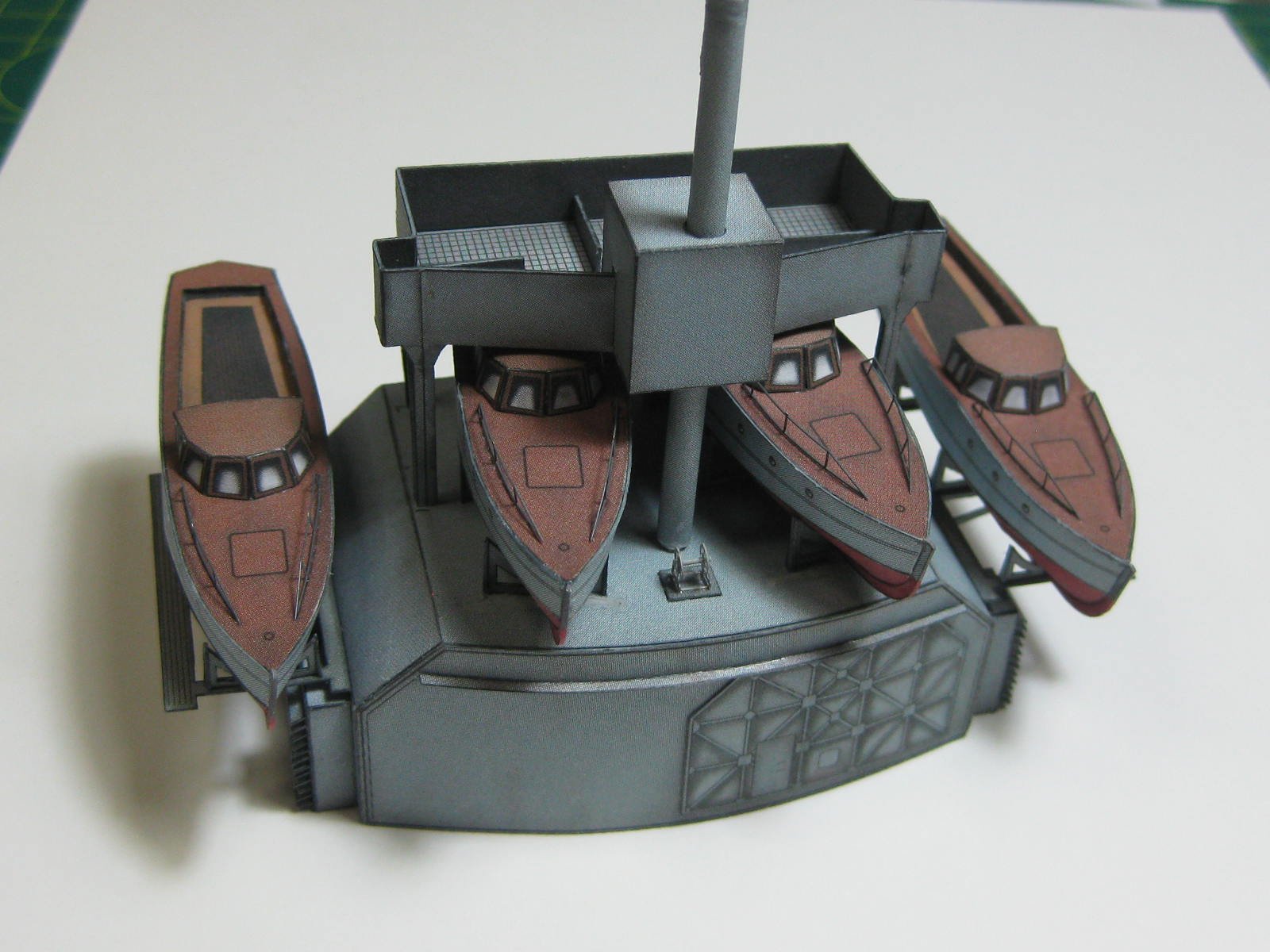
There are a total of 13 Ship's Boats of various types to be built. I needed to make and fit four Motor Launches to continue with the Aft Superstructure. I figured it would be rather difficult to fit them later on, and I was proved right - it was hard enough to fit them without anything else in the way. It would have been nearly impossible to do a good job of it once the mast and platform were in the way. The kit supplies a rudimentary laser-cut framing for the hull, consisting of two pieces. I added more card to them to prevent any crushing as the hull was skinned : Here are the pieces for these four launches : I cut out the middle of the decks : And most of the pieces for one launch cut out : Assembly starts by gluing the flooring underneath the deck. This was then glued to the framing, and the transom was also added : I shaped the hull skins with a rounded stick on my piece of high-density foam : Next one skin was glued to the edge of the deck : The aft end of the lower hull was then glued on, then the bow section, finishing off with the two middle areas. The fit of the sides was very good : The four hulls skinned. You can see the improvement in my technique - the first one I did is on the left, the last on the right. All are acceptable however, as the boat racks hide the worst joins : Now I folded and fitted the cabin. That sounds easy when you say it fast, in reality they took me half a day to do : The finishing touches included two railings on the fore deck, a rudder, a propellor shaft and the tiny (2.5mm) propellor from the PE set : The four launches fitted to the main hangar. I had a lot of trouble with the racks for the two middle boats, having to cut the central ones down about 1mm and removing, trimming and refitting the fore ones further aft. That's what happens when you trust the kit to have things in the right positions, only to be let down once again . The middle boats aren't fitted crooked, that is the way they have to fit to clear the mast platform : Danny
.thumb.JPG.c9d1e61d784b6135efdcde97c71b2685.JPG)
.thumb.JPG.41dbb6c0e410d245a7c2967973d2e467.JPG)
.thumb.JPG.15dc7c22e08eba112228c5830ca1e0d9.JPG)
.thumb.JPG.f521a2249d38f9cb9f4931c664f3aa01.JPG)
.thumb.JPG.bcbd8b01d3f404c1651ca1c323389997.JPG)
.thumb.JPG.5e3bf6ab1044100b6a3b941dbee9916e.JPG)
.thumb.JPG.de9eba35f79bfe60d4dd5a2850d2092f.JPG)
.thumb.JPG.9204312b8ba1c2d36d869c84453e9d68.JPG)
.thumb.JPG.8e093028c76c678037aab664e2cbcb03.JPG)
.thumb.JPG.44475b595ab9d9773977b9b8d703e9e2.JPG)
.thumb.JPG.4dff746d2765585ce4b1fe5854c4e6c8.JPG)
.thumb.JPG.1f5be36806afa5f04b78a9669bf7cc68.JPG)
.thumb.JPG.955aa5afb019cfe0e9ed6baada258d9b.JPG)
.thumb.JPG.29c295d429f8e949b75c4dd9c371fa8d.JPG)
.thumb.JPG.76d7902d5d5addcf9ae8bd99da15571e.JPG)
.thumb.JPG.9878bfcce6b0f37ee3281908dedbb6f3.JPG)
.thumb.JPG.284969f313e22a568d5d72eef7d7ef34.JPG)
.thumb.JPG.bf100995a9491a29906327ef5dd3064e.JPG)
.thumb.JPG.0c8759ae560e61b83a2620a710c2cf96.JPG)
- 524 replies
-
- 20
-
-
G'day Galen. One tip when painting - always (when possible) paint the lighter colours first followed by the darker ones. You won't have the trouble of using multiple coats to cover the previous colour. Another tip for masking - Tamiya Masking Tape is probably the best you can buy. It's edges sit really tight and you don't get any bleeding under it, unlike "normal" masking tapes. It comes in a large variety of widths. I agree with your finding about Acrylic versus Enamel - I much prefer the Acrylic. The best I've found to date (and I don't paint much, hate it in fact) is a brand called "Lifecolor" - seems like hundreds of colours and it covers really well. It doesn't dry too quickly either, so you can get a nice even coating. Danny
-
Now that we're back on line at last I can put in an update. There are two boat racks either side of the main hangar, similar to the ones I built for the other hangars. These have turned out a lot better than the first ones - something to do with gaining more experience perhaps : The main hangar with all the racks fitted : Next up is a platform at the bottom of the main mast. The design of this was a bit ordinary (no - a LOT ordinary) to say the least. Why they thought it was a good idea to make the join in the middle of one of the support legs is beyond me, but I'm starting to think that there may have been a lot of Slivovitz consumed at the time . I decided it might be a good idea to make extra support angles for the inside of the legs - the single-thickness paper wanted to crumple at the slightest touch : I also made gussets to strengthen the tops of the legs, and wicked some CA down the full legth of them. They can now support a VW beetle (almost ) : The finished platform : Danny
.thumb.JPG.b70e92ae7d4f99667ef00c2f89a82c7f.JPG)
.thumb.JPG.3b50f26f3dfce97b2a60e65232f88b96.JPG)
.thumb.JPG.83dc17877a1c8f9fb3e3632fa8ad9d55.JPG)
.thumb.JPG.05a2686fab7c527ba22f295b1a7599d2.JPG)
.thumb.JPG.2dbd7bfc33ec52f06ca2777cac84b325.JPG)
.thumb.JPG.f044db609f0ae57f1523b483fb4b9f41.JPG)
.thumb.JPG.8aebab48c66d497839069fc98e9d164f.JPG)
.thumb.JPG.66d1dfce0e0dd81034eff114f56455b3.JPG)
- 524 replies
-
- 14
-
-
Looks great Scott, apart maybe from the Hot Rod Silver . Be careful with the way you have your knives stored in your Organiser, won't you. Is there a spot for Band-Aids? Danny
-
Thanks Grant . It's called Zap-a-Gap, and is available in thin, medium and thick types. It comes in plastic bottles in three sizes. I don't buy the thick type, as the medium thickens up a bit after time. My local hobby store sells them, and they are also available on-line. Harvey, the answer is - CAREFULLY . Actually I have 0.1mm drills as well, but they are a bit on the fragile side and I haven't really found a use for them yet. These are tungsten drills and work really well on paper. I've also used them for drilling PE, and to date I've only broken three. Most times I just use them by hand as they are, but they also fit into a pin-vise when needed. They are available on-line, and I get mine from THIS SITE. Danny
-
Thanks again for the replies John, Mark, CDW and Popeye. There is a small winch on top of the hangar. The kit supplied one was a woefully simple thing made from a "U" shaped piece of card and two plain wheels. I had a lot of PE ones left over from the supply I bought for Amatsukaze so of course I used one of them . The PE set for Bismarck did have the wheels for them, but I used all the IJN ones as they fitted together properly. They are slightly larger than the kit ones, but overall look far better : I had to redrill the tiny holes in the wheels and frames. The smallest useable wire I have is 0.2mm, I think the holes were about 0.15mm. To drill the holes I used one of my tungsten PC Board drills. The centre pipe is a piece of 0.5mm tubing, the 0.2mm wire goes through all of it to hold the whole thing together before CA glue finished the jib : After painting. Speaking of paint, I've found this Lifecolor stuff to be excellent. I was previously using Tamiya Acrylic but it's rubbish - dries out on the brush and doesn't cover brass very well at all : The winch fitted to the hangar. I'll give it a 2nd coat of paint now that I've seen the thing in closeup : Danny
.thumb.JPG.993daabbf17d37a779131370f37d78d3.JPG)
.thumb.JPG.eb340adda8674b46fefd8d8efeeb16a2.JPG)
.thumb.JPG.2a86cb3f5169178781399d3daf3cf58b.JPG)
.thumb.JPG.43ec54b7eec5e9c8af7ace2c36183a18.JPG)
.thumb.JPG.a47f6518d86a5c4b75cd8bec96188515.JPG)
- 524 replies
-
- 10
-
-
Get down and boogie ..... that's awesome Grant . The "scale" speed even looks right. Now .... how do you get a waterskier up behind her ??? Danny
- 339 replies
-
- 4
-
-
- dumas
- Chris-Craft
- (and 3 more)
-
That's easy to do on rounded pieces, I've done the same myself occasionally. What looks good on a computer doesn't always work in reality . Yep, looks good from a distance . Danny
- 64 replies
-
- 5
-
-
- v108
- digital navy
- (and 2 more)
-
Thank you Henry . There are boat racks similar to the ones I made earlier fitted to the large hangar. Below is a step-by-step sequence showing how I make these rather tricky items. I learnt a few things NOT to do on the first lot, these have turned out much better . Here are the parts for all four racks : A closeup of the parts for the two racks in this post : First step is to cut out the middle of each part. I use a 2mm wide chisel ground from an Xacto blade. I sharpened the chisel several times during this procedure. I can't emphasise enough how vital it is to use SHARP blades, especially on thin and delicate parts : Once the middles are cut out I use a BLUNT Xacto blade to score the fold lines. I've specially ground this blade with rounded edges. It works great, much better than the awl I was using previously. It's a good idea to score any fold lines prior to cutting the piece out, as it's easy to miss one or more after the fold marks (the little lines outside the edges of the piece) are in the bin : When the middles are all cut out I edge "paint" the cutouts using a Pitt Pen, approaching them from the back side to avoid smudging the printed side. Doing it now means less handling of the delicate pieces, the less handling the better as it can damage them after a while : After leaving the pieces to dry for 10 minutes they are cut out, once again using a SHARP new scalpel and a steel rule for the straight edges. I replaced the first blade about half-way through this job. To avoid crushing the pieces for the last few cuts I pressed them down with my steel rule and free-handed the curved edges : Folding the pieces in half presented a new problem. I could have simply cut them in half and then glued them back-to-back, But that would have presented another problem in that one edge would have been square and the other at an angle. This happens with every cut, due to the thickness of my steel rule (it's the thinnest one I could buy, only 0.55mm thick). The blade has to be held at a slight angle away from the rule to make a square cut, but due to the bevel on the blade the right-hand side of the cut finishes up at an angle. If the cut isn't square the piece won't stand straight when it's glued on. Trying to make a fold in a piece that's only 1.8mm wide using 0.2mm paper is not easy - usually. It's nearly impossible to hold one side down with a steel rule and then use a single-edged razor blade to fold the other side up - the rule keeps slipping. To get around this problem I used my PE folder. It clamps the card down without any chance of it slipping and deforming the edge : Once they are bent a little PVA glue was brushed thinly to one side and the piece squeezed together with my fingers. Any slight mis-alignment could be adjusted before the glue dried. Then I pressed it down again using the PE folder. The results were excellent : The pieces were glued to the roof of the hangar, and a small brace was fitted to each end : All the first lot of racks fitted : Danny
.thumb.JPG.2ec14c547e34a061c80fbad7f5370d4e.JPG)
.thumb.JPG.bf8774c850b74d9b0a88229acb034c44.JPG)
.thumb.JPG.7d9ea1338adf769148d9ed50f30bce93.JPG)
.thumb.JPG.4bab2f7177bd8cfa93850a37c00d4a2b.JPG)
.thumb.JPG.36ba22ecc0dd05d87baac866f79c1f4a.JPG)
.thumb.JPG.a0d6cb5480d14d0dcf312d24bd374d97.JPG)
.thumb.JPG.6cf64a5c36dda79baae576955dd99ada.JPG)
.thumb.JPG.41814603dae8444c6a3ea327fd0cce01.JPG)
.thumb.JPG.532d382714797fe07fffaad50cf8c6d5.JPG)
.thumb.JPG.2fa7a26d7b8b56ff31ebe4230c1adc00.JPG)
.thumb.JPG.fc1556f5cf887f7d99d057a8aadcee96.JPG)
.thumb.JPG.8d8e596da78cfbb6996c2c9f47333c46.JPG)
.thumb.JPG.a421cfad146d995d8127b0e248da96b3.JPG)
- 524 replies
-
- 20
-
-
Without trying to sound too critical Jan, if something needs that amount of pressure to make it fit that it cracks the hull there's some sort of problem that should have been fixed before gluing. If all things are right you should only need enough pressure to keep the joint tight until the glue dries. It looks to me like more "dry fitting" may have prevented this unfortunate incident. I think the framing card is far too thin for a model of this size. Most kits use card of 1mm thickness for the framing, which is strong enough to support a small car (maybe I exaggerate a little ). Another thing to watch out for, and I've had this problem when I first started using card, is to use as little glue as possible. Too much glue softens the paper which can cause it to buckle. Danny
- 64 replies
-
- 5
-
-
- v108
- digital navy
- (and 2 more)
.JPG.44259adcee48a5a9f9f8f446b5d5f327.JPG)
.JPG.9bb6d3016079289711f93f3594ac56f1.JPG)
.JPG.8faf06b444c3869db5d4c3ba5cc875ab.JPG)
.JPG.98dd58290809fcc41b79ade7afb156f7.JPG)
.JPG.5e88ca945ca5809154fb84e6e5f72eca.JPG)
.JPG.b9d5fb5eb49ccd2d65f9024b727272f1.JPG)
.JPG.0b5bfc8b55366ac2afe4f91eba3394ea.JPG)
.JPG.bf469337c1009b564ca30d330c87a507.JPG)
.JPG.fafff54c59d793b3650c1c18b8b8aa10.JPG)
.JPG.8cb3bede393fe08f2c70d7a10736c75e.JPG)
.JPG.f1e79e0fd07e31cd8b523025dcae5455.JPG)
.JPG.25a446ee14b74030af086601a0c2bfc0.JPG)
.JPG.da2293e4392db722180aab7adedb62ee.JPG)
.JPG.c2cb788fe069154c89738ce6852e5a3b.JPG)
.JPG.2fbf803ef2c21ef702f4dc216b00ff92.JPG)
.JPG.a10da9f70a899268009042a6c69f97cc.JPG)
.JPG.1cb15b9bce5e8b088fc8197dff863fed.JPG)
.JPG.8d31b838d19f0bb0aa12d7e4799971de.JPG)
.JPG.0c44434b520763cf6763965203b5322b.JPG)
.JPG.570ff12bc11b586167f516761df95f0f.JPG)
.JPG.cb2939386ae880dcf9c47d63e0251407.JPG)
.JPG.60ef74703c9fbc491398772c83228771.JPG)
.JPG.8b6f5b592f8beae0625d8323a6cd1f4b.JPG)
.JPG.8ded94e5a750d2c8dbd931700f7fcb05.JPG)
.JPG.97402c5f0a6977f5733ceedd77809a95.JPG)
.JPG.f0f9e72b76ea58d112f45eeb3f14ce3f.JPG)
.JPG.1f1fe2495df51a306ce7512fe2990adb.JPG)
.JPG.e2b4b349ec3257d72809a6e4ec830669.JPG)
.JPG.0bfb438fa29fe304bf8253a338602d3d.JPG)
.JPG.8a514c3212de64c82554f380a02319c3.JPG)
.JPG.585c1609cbc29f34cb730f14245d9416.JPG)
.JPG.d65f0b1ba80341829ebf4aa3ab0cb194.JPG)
.JPG.cda6a1c78b2cb33efd9680ec0ffbf518.JPG)
.JPG.4759d40cf0191e50cdce9833eef9ce63.JPG)
.JPG.656dfc69d401a443fcec3372546ac14d.JPG)
.JPG.dbbfb3936dbb1a7e468ddef61b631bb3.JPG)
.JPG.c3512fdfb4e8002e18f6f11c194f1960.JPG)
.JPG.774a59478940e7602773a3ca1cf28baa.JPG)
.JPG.9b864266b7af2ad1d6fee5021318527d.JPG)
.JPG.d1cb598ea2e66ede43bf524ea98a7ae0.JPG)
.JPG.cc3625e03eb14a5ae6a1aafafb59e8c4.JPG)
.JPG.b0e8afd76554511af36c58a6e54d0f92.JPG)
.JPG.d8740819d779666ae53eb9972dd42475.JPG)
.JPG.1f7150e669839ff2d01aa5a055c3f89f.JPG)
.JPG.ea75272a286f919f62a9e0186d8b1c99.JPG)
.JPG.678e5ffd0bf1aebed437fb9d05c8d234.JPG)
.JPG.5f4817769261cdf35ff24a9a8ee08285.JPG)
.JPG.6f59bf28fa4f204c5e5d6c5f4dccb005.JPG)
.JPG.dbc8d36bad4ba9777781a3754b6a7ccf.JPG)
.JPG.7590f645979c9ccc948835f103106eb1.JPG)
.JPG.5b64d60bd78b14dd58262c3541da4017.JPG)
.JPG.38b478d0345d80894733787b1d9d744e.JPG)
.JPG.a5008297a00027facc39c2d7a4f3f2f6.JPG)
.JPG.e6059f72514c7c279b60d68fd78cd149.JPG)
.JPG.854f648a894bd62401acee0f0a34642b.JPG)
.JPG.e8a94e83f42f9bd773f8f86d81b08aff.JPG)
.JPG.a35464e7ece88eca2e3d3e33479e6980.JPG)
.JPG.a6a74c541239f57396be349cc23bbf6e.JPG)
.JPG.033a3c8ff461c239255dd9812e6073a6.JPG)
.JPG.b2e71135c7f66f7984570767b61915e6.JPG)
.JPG.885ec4c35deb0f549c7754185e4f6f16.JPG)
.JPG.924dbc87633aa011fefc1141ecab5cac.JPG)
.JPG.df16a4a82d746aa6685e9c589b3009cb.JPG)
.JPG.3cc576d59d21a0b42b58721b0f96dc04.JPG)
.JPG.226bb3bc32e6ff3e600524d76c900844.JPG)
.JPG.b271cf805eabdabed8d73b17edb290dc.JPG)
.JPG.d8a3fadc0370f4a02e410e451a7a6a0a.JPG)
.JPG.c95efab65abc0fa5b7a465ac4035d0ec.JPG)
.JPG.c35fb8f7cffa618bd6fd6b29e5320820.JPG)
.JPG.1012a78879f26c0b2e46f03711652684.JPG)
.JPG.edbb64dcf2828d8fc27b7f29564bf553.JPG)
.JPG.143845840dd324be067123eebb7ffa69.JPG)
.JPG.d12e502f54efb4841516e2af21927d72.JPG)
.JPG.f532bd9b240c4b84af41152a75e01eff.JPG)
.JPG.2ed4e323f679bf4c80707444d369af47.JPG)
.JPG.01079567ca56458152f209a105aaf472.JPG)

.JPG.b51a9d4f3ed4ba77ad48c6296ed0d465.JPG)
.JPG.6279f4ff0bd0b4bc264e4c257f80548b.JPG)
.JPG.204362e1d99bb205ab722ab027e8211b.JPG)
.JPG.e0a76b2a07f19f2cc120b41868a103f0.JPG)
.JPG.520a6aea5ba340797e6d79fa67d4aece.JPG)
.JPG.7d3b7549109a3adaa0837e917921e279.JPG)
.JPG.45a7c7f88d47f95e58b4a9409140a8df.JPG)
.JPG.44616a1205fbdf1eb4f7367a859b6964.JPG)
.JPG.434a3ca17f4fd9bff4a7e6d56e82dcd6.JPG)
.JPG.4df8ea132cb511cb4ca1a7105991a3a8.JPG)
.JPG.97feac07aa876f239dbf0788325e1e8d.JPG)
.JPG.9d6b2c04703bfd6e380a92390f338621.JPG)
.JPG.e5b3a2b33a09ebb8d790063abdde4f70.JPG)
.JPG.3b5cd038e02f43c4d6e7bf6ac20e7315.JPG)
.JPG.b91397bff601594b35607bb978b603c3.JPG)
.JPG.4e1723eaa957db3bae89902c01195a73.JPG)
.JPG.567755cbac026307e757649048f734a1.JPG)