
HOLIDAY DONATION DRIVE - SUPPORT MSW - DO YOUR PART TO KEEP THIS GREAT FORUM GOING! (Only 13 donations so far - C'mon guys!)
×


Dan Vadas
-
Posts
3,261 -
Joined
-
Last visited
Content Type
Profiles
Forums
Gallery
Events
Everything posted by Dan Vadas
-
The support framing for the 2nd Decks supplied with the kit is very sparse, to say the least. The kit's is only the central piece and three athwartships frames on the fore deck section, plus the two larger "V" shaped ones on the aft section. I've added a lot more to both of them : I glued the decks on, using weights to hold them flat, and let them dry for a few hours. Then I prepared all the bends before attempting to glue the sides of the decks on : I'm very happy with the way these decks are coming out - everything fits really well, due in part to the extra bracing. They are also dead flat . Danny
.thumb.JPG.2df11510f434a87d47daa0487971c901.JPG)
.thumb.JPG.e6d14d05b3a23f4bd88cf6a26f493766.JPG)
.thumb.JPG.6cc9dd2700155a9bdf0a0039ce59b29f.JPG)
.thumb.JPG.131ced9597bda3953e7b8b60b739ac23.JPG)
.thumb.JPG.a3c99469ab548f5a9a4f3e6978cd894a.JPG)
- 524 replies
-
- 18
-

-
It could be any number of things. 1. If you're starting at the keel, shaping the Garboard Strake (the first one that butts to the keel) is very important. It's different for every ship, and especially on bluff bowed ones with rounded hulls (18th century for example). The top edge (furthest from the keel) should be straight, shape the edge that butts against the keel. The forward end of this plank will finish with a sharp point - that's OK. All other planks should be no less than half their width at the narrowest point. 2. Bear in mind that there are virtually NO runs of planks that are a single width for most of their length (depending again on the shape of the hull - older ships have more taper than. say, Clippers). They will need tapering for a LOT more distance than you have been doing so far. 3. Don't attempt to lay a single plank the length of the hull. It's much easier to lay them in the correct scale length - between 20 and 30 scale feet. Kit bulkheads are usually too far apart to be too critical with these lengths, just go to the nearest one or add extra bulkheads or filler blocks in the bow and stern. 4. Start in the middle of the ship for each run. The planks usually don't need much of a taper in the middle, if any. Bend the plank over the top of the one already fitted to gauge how much will need to be removed from the BOTTOM edge until it gets to half-width. A Stealer will need to start from that point. Shape your plank and glue it in. Leave the stealer until you have fitted the next plank. 5. A good trick is to temporarily fit a plank about every 5 or 6 planks apart for the full length of the hull,without laterally bending them. Measure the distance between the TOPS of the planks at each bulkhead to see how much they will have to be tapered at that point. Mark the bulkheads, and divide the measurement by the number of planks to get the width of each one. If you hit the marks when you get that far you will know you're on track. 6. Thicker planks (0.6mm or more) will need to be edge-bevelled as they curve vertically to avoid gaps. 7. Always dry-fit each plank and reshape it until you are satisfied with the fit before reaching for the glue. If it's shaped and bent correctly you hardly need to clamp it other than to hold it flush to the bulkheads until the glue sets. It goes without saying that the bulkheads should be properly Faired before starting any planking. Take a look at how I did the planking on my Norfolk Sloop to get some ideas. I do a "plank by plank" description in that build log, it won't apply to any other ship but the general method is the same. Danny
- 29 replies
-
- 17
-
-
Looking good Doug . One point, might be a bit too late for you. The forward "Gun Port" isn't a gun port - it's known as the Bridle Port, and swings forward rather than up. It's used for ventilation to the forecastle, and for access to the anchors when shipping them. See THIS LINK to my build log of HMS Vulture (another Swan). Danny
-
CDW - to be honest, I haven't really checked the "instructions" () for some time. As you stated it's just "best management practice" - it can't hurt, as long as you remember to allow for the extra thickness later on when cutting bulkheads for the upper decks . Popeye - I actually laminated the decks weeks ago when I did the main deck sections. To make cutting through the extra thickness easier I first cut out and trimmed each deck section, glued it to the card, and then only had to cut through the extra card the 2nd time. Trying to cut through two layers plus glue can get rather difficult, as I found out on the main deck sections . There's always a little bit of warpage as even Contact Cement will shrink a bit as it dries. It's easy enough to flex in the opposite direction to flatten it out again before gluing to framing etc. Danny
-
I take the "section by section" approach to my models as well. As Yves said it makes keeping track of all the parts a lot easier. One thing I'd do though - I'd leave painting each section until they are ALL done in case there is an "overlap" with some parts, and also in case there is any filling needed between sections. You'd also get a more even colour overall. Danny
-
Thank you Remco . I sometimes have to take a few fractions of a millimetre off the edges to get them to sit flush together on the butt joins. Occasionally I may be just a fraction off line when I'm cutting freehand (e.g. without using a straight-edge on long curves). I use a sanding stick with either 150 grit or 360 grit paper, depending on how much I have to take off. It sands surprisingly easily. It's virtually impossible to take this little off with a scalpel. Other sanding is necessary when I have to use putty over a larger area than I can scrape off with a narrow chisel. Danny
-
Thanks for the comments guys . The hull and main deck have been coated with Testor's Matt Clear, one coat on the deck (it'll get more later when the superstructure goes on) and two on the hull. I've also cut out and laminated most of the other decks to 0.5mm card : Danny
.thumb.JPG.4377419e7b256a99ae8a62fcab1068ef.JPG)
.thumb.JPG.6b13d8e6576a5cc96b4cab8d8c472dcf.JPG)
- 524 replies
-
- 14
-
-
I've finally finished all the hull, including the touch-up painting. I managed to match the colours very well. They'll look even better when the matt clear goes on : Danny
.thumb.JPG.725f628a9cd7d92b19bb1b1c307476d7.JPG)
.thumb.JPG.03e3650b0ce1217cc14de5313f82d29b.JPG)
.thumb.JPG.2a89d768cf3f642ed572db0885b1da63.JPG)
.thumb.JPG.cd0c39dede81886f738116323f8bf3dd.JPG)
- 524 replies
-
- 14
-
-
Thanks for that Pat. As it happens I have a very good source of information (HERE) kindly supplied to me by Wiley in the other forum I posted to. It has everything I need, and the best thing is that it's almost exactly the same as the screws I'd glued together just before I saw the post . The pics clearly show the screws the way I'd figured they would be, two clockwise and one counter-clockwise. The only difference I could see was that I didn't give them quite enough pitch, but I can live with that : Here are the parts for the outer housings. The "hourglass" shaped ends didn't have laser-cut bracing, so I cut a couple from scrap card. There's a fair bit of stress on the ends when the sides get glued on. As usual the kit design is inadequate : I decided to see if I could roll the shafts from card instead of using styrene tubing or brass wire. I'm pretty happy with the result, even though they aren't quite perfect. I used some styrene clamps around the appropriate size drill bit to help with gluing them : Some of the parts for the housing, shaft and screw assemblies : The housings ready to fit to the hull. I think I'll leave the screws off until later in the build. I still need to do some other work on the hull first. Nothing has been painted yet : Danny
.thumb.JPG.3d3f80fa89ae771f1d38d73cac520aa4.JPG)
.thumb.JPG.1b57f17f7d03b7805c2aba536cf9c2f4.JPG)
.thumb.JPG.ab6f7a8ae8df36dc13f8557627bcbda7.JPG)
.thumb.JPG.72aa82f97761589b3083c3ac6223493e.JPG)
.thumb.JPG.1fc8da8591c3042b182a4c475e9ce2e2.JPG)
.thumb.JPG.f9987f4ec7e208be926cd6a34afd996d.JPG)
.thumb.JPG.f8b5a278aa0c3d8919c867bb3100e3a3.JPG)
- 524 replies
-
- 18
-
-
I'm currently working on the Propellor Housings, Shafts and Screws. I'm a little undecided as to which way the screws should turn. I've Googled "Propellor Rotation" and come up with either conflicting opinions, or "it doesn't matter". Any thoughts? as (of course ) there is nothing in the kit instructions regarding this. I'd guess that the Starboard screw should turn clockwise (viewed from the stern) and the Port screw anti-clockwise as per the usual twin-screw method. This could be open to conjecture, as I've found that Titanic's screws were the opposite to create more prop wash to attempt to assist the (undersize) rudder to work more efficiently - whether that contributed to the collision with the iceberg may have been a possibility but that's another story. In any case Bismarck has twin rudders, so that wouldn't have been a problem. So the question is - which way did the central screw turn? I'm guessing it wouldn't have mattered either way, but if anyone has definitive information it would be appreciated before I glue on the blades. BTW - I'm going to duplicate this post in "Ship's Plans and Project Research" in case someone who doesn't follow this thread has the info. Danny
-
Jeff, check that blades for whichever saw you decide on are readily available. It shouldn't be a problem unless you buy some obscure brand that only supply their own blades. Prices sound good . Danny
-
Jeff, the first power tool I bought over 40 years ago was a Scroll Saw. My 2nd wooden ship model was a Billings "Norske Lowe" which had ply frames that weren't even die-cut let alone laser cut (long before lasers were commonly used). That old Dremel saw still works, despite making about 1,000,000 inches of cuts (a guess ). As it looks like you will be starting a fair bit of Scratchbuilding I'd strongly suggest you look for one. It's a lot more versatile than a Band Saw or Table Saw, and a hell of a lot easier than cutting ply with a fret saw. You don't need one with all the "bells and whistles", a cheap but reasonably good quality one will be adequate. It shouldn't set you back more than a couple of hundred at most. THIS ONE is typical of what I'm talking about. It's in Australia, but you get the idea. Danny
-
It works fine when you set it up correctly (Setup Instructions are included). The only addition I would have made to it is a bar to hold the thread spool. One of these days I'll get around to making one myself and attach it. The powered version is great, gives you both hands free if you need them. Danny
-
Swann-Morton Scapel
Dan Vadas replied to Landlocked123's topic in Modeling tools and Workshop Equipment
The first video is exactly how I do it, but using needle-nose pliers instead of any special gripping tool. Thanks Bob. Danny -
Swann-Morton Scapel
Dan Vadas replied to Landlocked123's topic in Modeling tools and Workshop Equipment
First thing is throw that blue box in the bin. Pretty useless . I simply use a small pair of flat needle-nose pliers, grasp the blade just on the "pointy" side of the slot and slide the blade down toward the handle until it clicks in. Removal is a reverse of the same, except I grab the end closest to the handle and lift the blade enough to clear the locator. I've never broken a blade or cut myself, and the only tricky one was the first one I tried (about 90 blades ago ). It takes me longer to open the pack than it does to actually change the blade . They get a lot easier after you've changed a couple. Danny -
The last Plastic model I made was before the invention of PE. Just kidding, but it seems like that long ago . In any case I was unaware PE existed at the time. Danny
-
Ah, but the feeling when it finally goes through is wonderful . Danny
- 3,618 replies
-
- 4
-
-
- young america
- clipper
- (and 1 more)
-
HERE is how I served the ropes on my Vulture, using black Quilting Thread. The description, and the advantages of this type of thread, are in the post. Danny
-
Thanks John . Wood is easier, but I don't really have a preference at the moment. I'd say they are pretty even. Danny
-
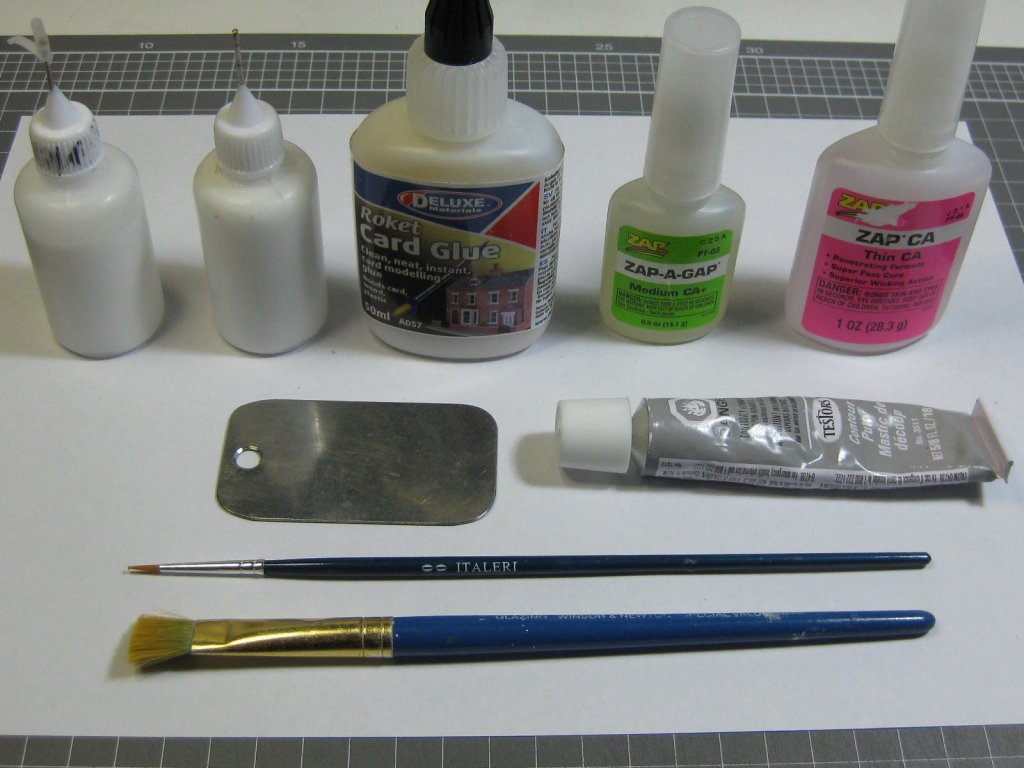
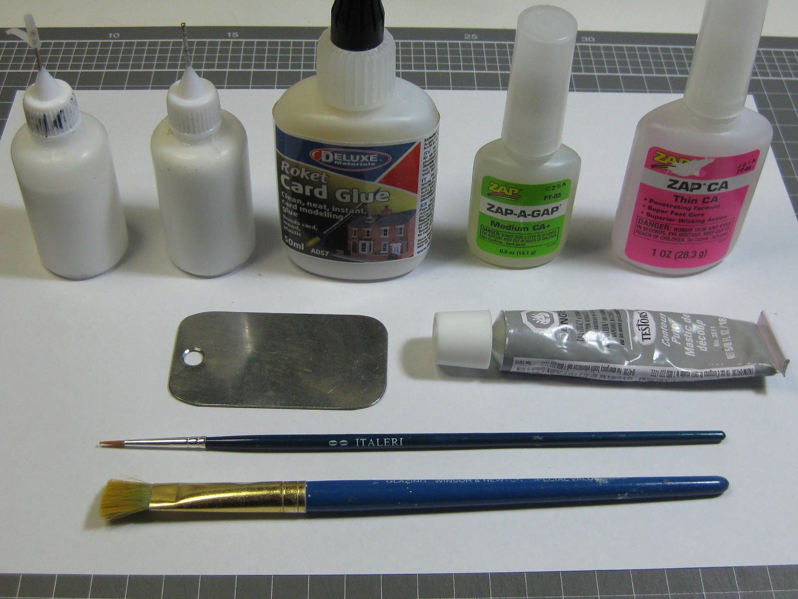
I'm using Testor's filler (grey tube in the pic below). It's designed for Plastic filling, but it works OK on paper. I find it's a lot finer than any of the Wood Fillers I've got. I squeeze enough out of the tube for the job I'm doing onto the piece of chromed steel in the above pic, then I use a flat Xacto chisel to apply it. It dries very quickly, so I thin it down with Isopropyl Alcohol as I'm using it by dipping the chisel into the jar of alcohol. It sands very easily too, using 150 grit for the initial sand, then 360 grit, and as a final finish I wipe over all of it with a Q-tip dipped in Acetone. Danny
-
I've skinned the Main Keel, which is also the housing for the central prop shaft. This went together reasonably well, except that it doesn't quite line up with the marks on the hull - both lengthwise and across the middle section. This is no big deal, as it will get a touch of filler at the join and then some touch-up paint : Danny
.thumb.JPG.6b61f8e503802c8b1845289126ff2306.JPG)
.thumb.JPG.5e5e6ea7814359998c1150a725eb99a7.JPG)
.thumb.JPG.cafab25dfdb7d3fe03bb91bc31f28d88.JPG)
.thumb.JPG.c9d46309e24d0beed39af36dfbfe3ea9.JPG)
- 524 replies
-
- 20
-
-
They are definitely the way to go . Actually I'm not all that happy with the laser cut frames on this model, they are a very loose fit. The frames on Amatsukaze were a much neater fit, not too tight, just right. Another reason I'll be going back to Halinski for my next card model. Danny
-
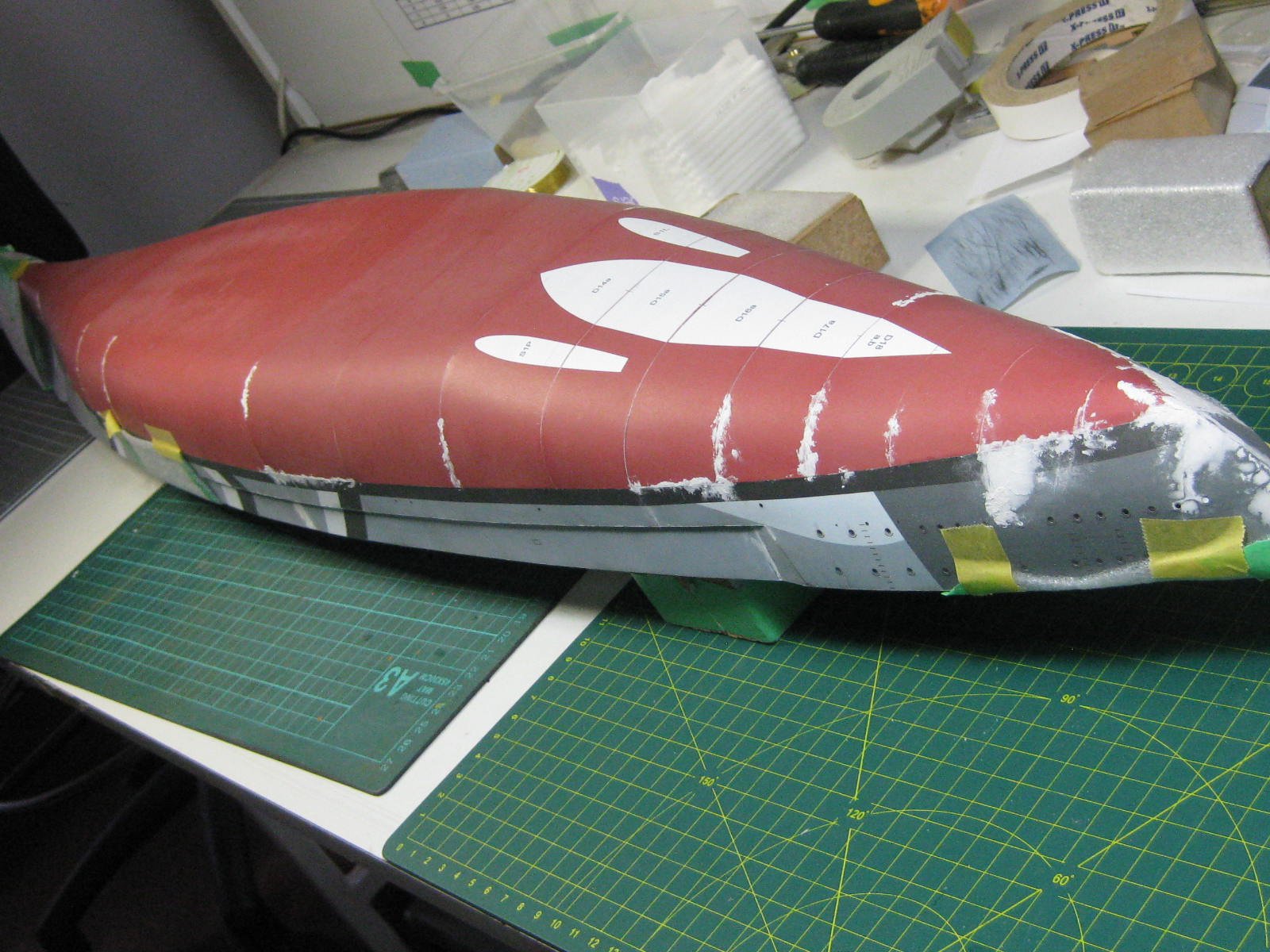
Thank you Pat and Hof. I've done a few more bits and pieces. The last of the Filler has been applied to the hull, I'll sand it down when it's dried properly : As I'm getting near the end of filling, sanding and touch-up painting the hull it's about time I made the Stand for it before turning it "right-way-up". I used 1mm and 0.5mm card in an "I-Beam" type configuration similar to the one I made for Amatzukaze. The holes were punched out with a 4.5mm die in my RP Toolz punch set : The two parts of the stand ready for paint : And with a coat of matt black. I'll give them a couple of coats of matt clear later : The last thing for today is the framing for the Main Keel : Danny
.thumb.JPG.2cf4261b91f5a985e3b054c747bc2a3a.JPG)
.thumb.JPG.3742f6fc0ee3c18e1f5785a8e5bc4dcc.JPG)
.thumb.JPG.cda00c9d5f2d45f04e3da661773aa8f6.JPG)

.thumb.JPG.65df0d53e69fb54b9f364041f02d3952.JPG)
.thumb.JPG.7ac2dce490b72288aceeb8925988e767.JPG)
.thumb.JPG.644b9d09df31cb0ab1b69a475d695649.JPG)
.thumb.JPG.727c116fdcfbbbd1a1bba8ead0bfd325.JPG)
- 524 replies
-
- 21
-
-
Pav, each "glass" is only a round piece 1mm larger than the actual hole. I used my punch to make them. The problem was that where the kit said to make the slit for the change of angle was just a bit too close to the last porthole. It was something I had forseen, but it turned out being worse than I thought it would be . I should have glued more bracing underneath the section where the slit was. I'd have had to fill and paint the slit anyway, now I've just got a heap more filler and painting to do . No problem, I can do that . I probably could have CDW, but I don't have any. Doesn't matter now - there are no more portholes to do in the hull. I'll be a lot more aware of this if there are any portholes in rounded areas of the superstructure . Danny
.JPG.fb012c0947fceca871f6e4c8cc75a6c8.JPG)
.JPG.752f1dfa614683b4b0aa5ed0c3bdd99d.JPG)
.JPG.811381f2a16c30cbf5a42c626ab0ecab.JPG)
.JPG.649db77533d34cfdd39953e63a6d4ed9.JPG)
.JPG.c319948727fd02b3408f19d9097fa40a.JPG)
.JPG.657cbf59445f628e8c598f9d6b7d9d54.JPG)
.JPG.ccaee123ad97714279b936ee8766b25b.JPG)
.JPG.624df608d3277d7dad77f6a1840427f4.JPG)
.JPG.2aa51a5fc35c898dabba6a40034f6270.JPG)
.JPG.1d807c582054b5281060efa2003b33b2.JPG)
.JPG.0fe86aac38a1237fe2c6caccdc3c9c02.JPG)
.JPG.6801562c4f49da28a4b9d224ba6a268c.JPG)
.JPG.1f2d8b9a24f252e324a38af75951e068.JPG)
.JPG.8a1607ca76b3064a2fec6e06da46acc5.JPG)
.JPG.1e9c51936f5143b00f440236c5e3db28.JPG)
.JPG.f9100a140f9f7d3bb712b04c5aa8037f.JPG)
.JPG.6413b580008750f99e6a6946de0f9edc.JPG)
.JPG.e88a402853404590768ac8ad700f2e00.JPG)
.JPG.e07ff26b7f82ae6484bc05be35032731.JPG)
.JPG.f9b1fb54beccd65d087f7a7a4c28ffdc.JPG)
.JPG.c2674c3812e47ff8ef95e678f6c3ad6b.JPG)
.JPG.e1c4d1278cb70b8827089d3d4ef970dd.JPG)
.JPG.9528729c24c0f34fbb8e6ccc6047f7f5.JPG)
.JPG.110cb46328c948aff56c61b476d5746d.JPG)
.JPG.c4cbd3f1b406b7e69bdae329ae8fc001.JPG)
.JPG.a52c82901380a27fdc55c2734290b99f.JPG)
.JPG.5be6becc4f420514d9bf3931e7790022.JPG)
.JPG.caacc2be4218b98daa1cb97a6d463fd6.JPG)
.JPG.36b94f8af4a8e86285a49f338a26c4d1.JPG)