BETAQDAVE
-
Posts
5,354 -
Joined
-
Last visited
Content Type
Profiles
Forums
Gallery
Events
Everything posted by BETAQDAVE
-
 The plans provided with my 1:96 scale Phantom from my Model Shipways kit that were apparently taken from H. I. Chapelle don't indicate any of the details that you show on your rendition of the ship. Perhaps they were just simplified for the kit, but it makes it hard to add those details to my version. Did the plans that you are going by actually show these details or do you have another source for them? They seem logical for other similar ships and I would like to remodify my version to include them if possible. On my plans the waterway and the margin planks are shown as one, their were no details shown for the hull counter at the stern, and the cockpit isn't recessed. The book you refer to is apparently only available in an E-book form, but I'm more of an old school hands on researcher that prefers an actual book, so I am still searching for a source for one of them and the blueprints that you are using. Bye the way, your photo images of your log are very well done. I look forward to seeing more.
 -
I inherited an old pantograph from my grandfather (circa 1925) that is made from boxwood. I used it once in awhile to enlarge or reduce ship model drawings. Unfortunately there are a lot of screw holes down the center of the beams that would really limit the width of wood to be salvaged. On the other hand, the arms are almost three feet long, so long narrow pieces could be ripped from them. Since I usually work at 1:96 scale I can fashion lots of masts, spars and decking from them. Come to think of it, it's really hard to find such well seasoned straight lumber so perhaps they could used to convert the plastic masts and spars for my 1:87 scale Wanderer to wood.
-
first time rigging - tools and books suggestions
BETAQDAVE replied to Frank Burroughs's topic in Masting, rigging and sails
I heartily agree with his recommendation, as I have three of them. I have very limited grip strength due to muscular dystrophy which makes their spring assisted easy action a blessing and the open handles (as opposed to finger holes) allow me to use all of my fingers to handle it. The micro-tip can get into very limited spaces and the blades are quite sharp! -
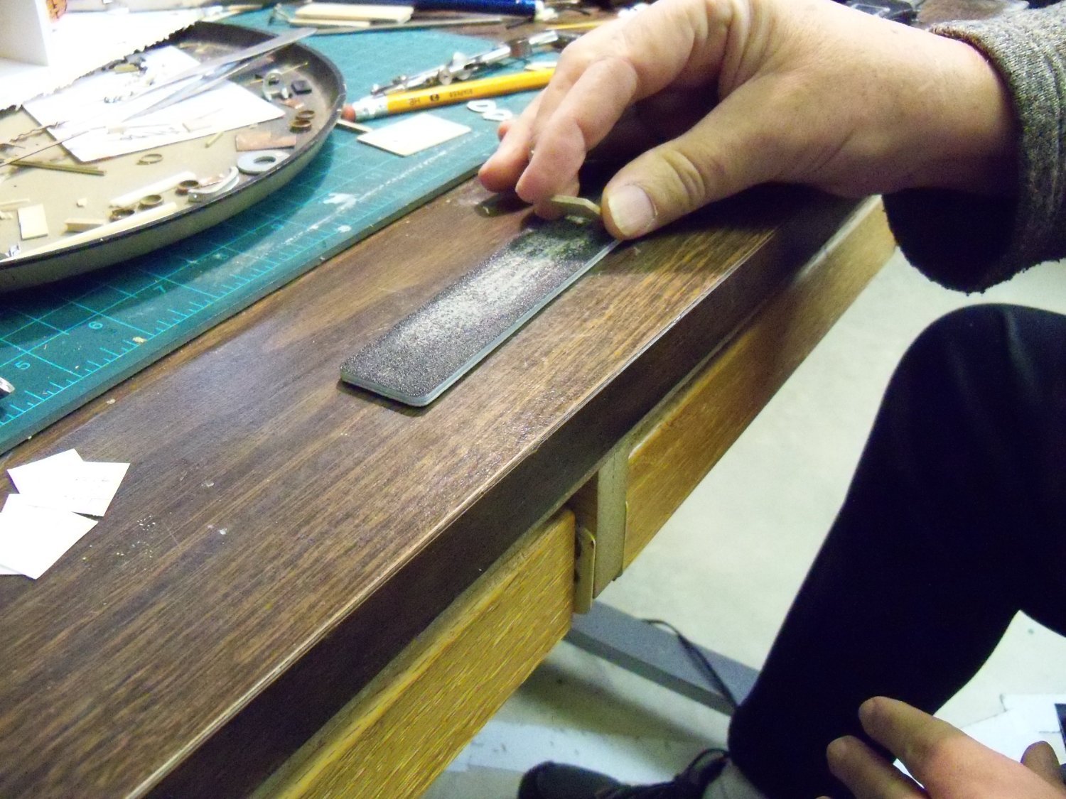
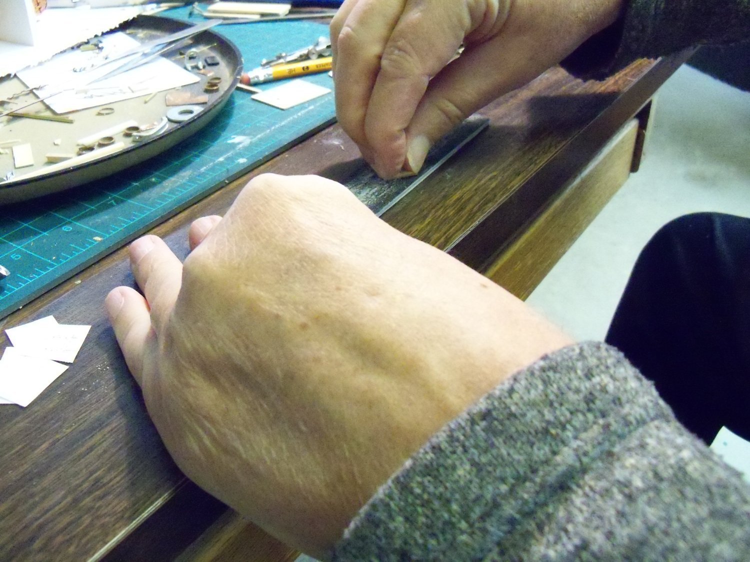
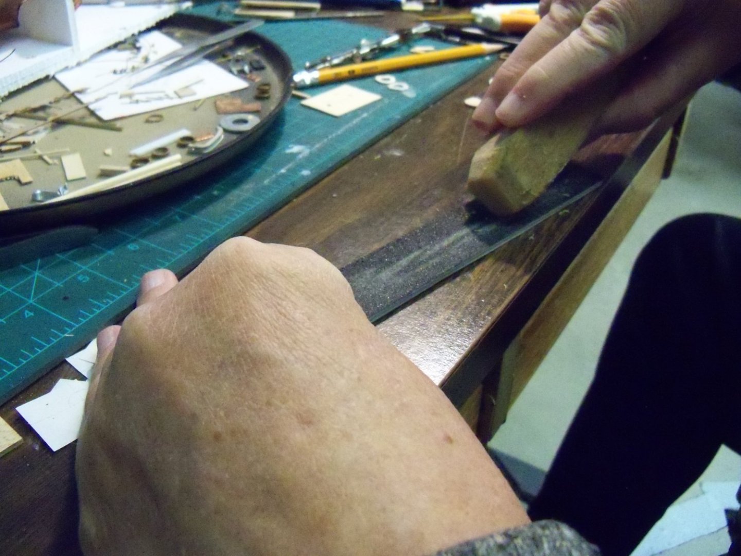
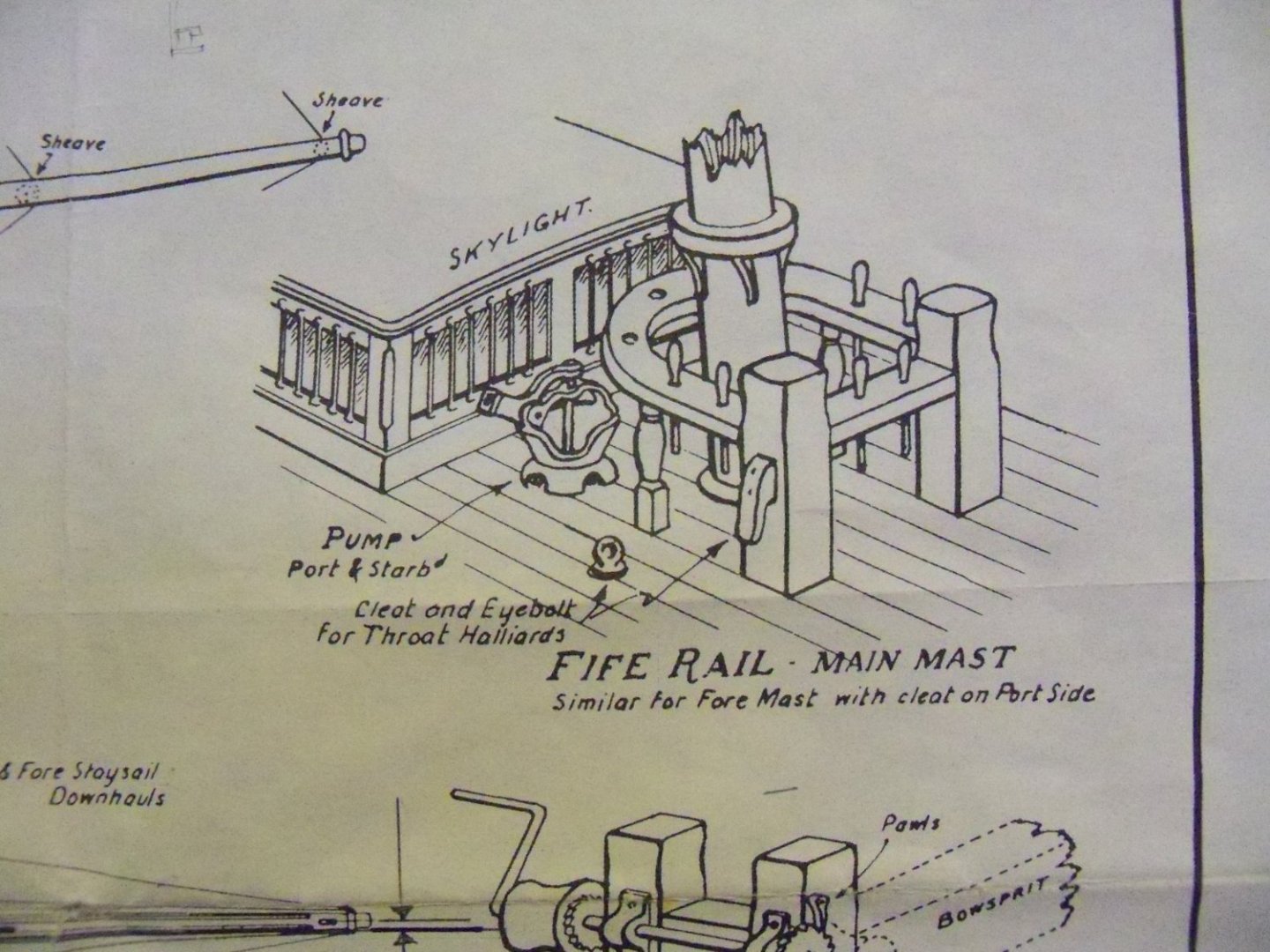
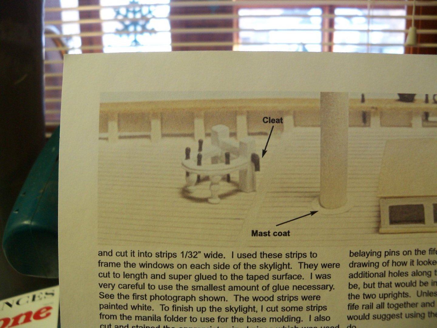
I’ve been away from this log for quite some time now for various reasons including spending time on my Wanderer project and some health concerns, but I’m back now to continue catching the log up with the actual construction. So now that the “easy” part was completed, it was time to make the fife rails. I originally tried using some 1/16” thick maple, but while trying to cut the shape, the part kept splitting along the grain of the wood. So the grain needed to be accounted for by using another layer of wood with the grain going the opposite way. Which is to say, I needed to make my own 1/16” thick plywood! Unfortunately, the thinnest maple that I had on hand was already 1/16”. This seemed to be a real problem until I decided to glue two layers of my 1/16” maple together with the grain running opposite to each other overnight and sand the result down to 1/16”. Sounds simple enough, right? The idea was simple, but to actually do it was another matter all together! Each of the layers also had to be the same thickness to get the benefit of alternate grain directions. I squared up the edges of the slabs and took out the roughest sanding stick that I had (180 grit). Gripping the small pieces with just my finger tips and nails, I started the sanding operation. After the first hundred strokes and measuring the minuscule results, I realized that this was really going to take some time! After each hundred strokes the opposite side was sanded to keep each layer equal and the sanding stick was so clogged with wood dust that it had to be cleaned up with my Magic Eraser shown below before continuing. As it turned out, each side of the two wood slabs required over 1,000 strokes to get to the required thickness. Once I got going, my stubborn streak took hold of me, and I refused to give it up, but ohhh, my aching fingers!!! I drew a template to scale on plain white paper for the fife rail and glued it to the topside of the slab with rubber cement. But then despite going through all of that work, I found that drilling the small holes for the belaying pins still caused the layer with the grain running the narrow direction to fail. I also had trouble when sanding up to the lines on the paper template because the template would deform or pull loose. Thinking that it was because of the cement, I tried using white wood glue, but it did the same thing. Finally, I gave up on using both the plywood and the plain white paper template, since the rails will be painted anyway. So I dug up some 1/16” thick scraps of plastic for the rails. I used drafting vellum this time and redrew them which held up much better to both the glue and the sanding. Since both the plastic and the paper were very slick, I had to machine it as if it was metal. So to keep the drill bits from wandering, a sharp metal awl was needed to dent the plastic for all the holes. The first step was to drill a 13/64” hole to give me the inside radius of the front edge of the rail. After that, I used some round and square files to clean out the rest of the opening for the masts. Two 3/64” x 3/64” notches were filed in the back corners to fit into the post notches. A 0.71mm bit was used to make the through holes for the belaying pins. (That’s 9 holes for the main mast and 8 for the fore mast as shown on the plan detail.) The fife rails were then turned upside down and a pair of 0.69mm holes were drilled for the top pins of the spindles. These were drilled just short of going all the way through the rail. Finally, the rail was filed down to the outside edges of the template. After pealing off the remnants of the template the assembly was test fit together as shown below. Once one of the posts was glued to the rail with thin CA, it was set aside to dry overnight. The next day the upper portion of the post was filed to its final shape as shown below. Now the other post was given the same treatment. I was a little careless using the thin CA to join the pieces as it had spread a bit too far, so the four closest holes to the posts needed to be cleaned out, but it was ready for painting. I wasn’t sure just how badly the Model Shipways paint would work in my spray painter, so I tried something a little different this time. I mixed up a small amount of light buff deckhouse paint with six drops of paint to six drops of water. Once mixed, I gave the parts four coats and used a blow drier and light sanding to speed up the process between coats. Actually, the Model Shipways paint I have doesn’t seem to be a very finely ground pigment as it definitely needed sanding between coats, but then my first order of their paint had several jars that were more like dried up hockey pucks than paint inside. On close examination I could see that they still needed a good sanding! How I miss the discontinued Floquil paint!! Although the spindles included with the kit for the fife rails were metal, they were still quite fragile to work with, not to mention the fact that just holding on to them is quite a chore. In Chucks’ practicum the spindles appear to be much heftier than the 3/64” ones included with my kit, because in that photo from his article shown previously, they appeared to be about the same diameter (3/32”) as the thickness of the posts. I thought about trying to chuck some 3/32” thick brass wire in my drill press to see if a decent copy could be turned with files and sandpaper, but for now I will try working with the spindles that came with the kit. Both ends of the kit spindle pins first needed straightening before they were filed smooth. These were painted with the same procedure and at the same time as the fife rails. Finally with the arrival of the warmer weather, the one hang-up of fixing my table saw was finally taken care of. One of the rubber caster wheels on the mobile base was crushed so I couldn't pull the saw out to use it. I enlisted the help of one of my neighbors to make the repairs, since I am not able to get down to the floor anymore to do it myself. Although I had some 2 1/2” caster wheels on hand, the wheels on the base were 3” diameter. The smaller wheels still fit with enough clearance, so we pulled the two wheels on the front of the saw and replaced them with the smaller ones which would least leave it balanced for moving the saw. Since those two front casters have some leveling screws alongside them that take the weight off the wheels when the saw’s being used, I thought that would be good enough for my needs. I still needed to dull the sheen of the copper plates on the hull anyways, the ship was removed from the base so I could trim and finish the base board. That took longer than I thought it would just to readjust the saws alignment. Maybe due to the fact that it wasn’t used in over a year or two? Once the board was trimmed and sanded, the ends and edges were given two coats of Minwax light oak finish while I gave the walnut pedestals a couple coats of hull black paint and set them aside. After everything was dry, they were all given three coats of satin finish polyethylene, lightly sanding between coats. While waiting for things to dry, I smoothed over the copper plating on the ships hull to make sure there weren’t any loose edges. I brushed some sun tanning oil on the plates and set the ship upside down in the sun for a couple of days. Then I gave the surface a rub down with a soft cloth and finally gave it two coats of polyethylene to seal it.


-
Pin Vise vs. Hand Vise?
BETAQDAVE replied to Balclutha75's topic in Modeling tools and Workshop Equipment
Same problem here Mark. -
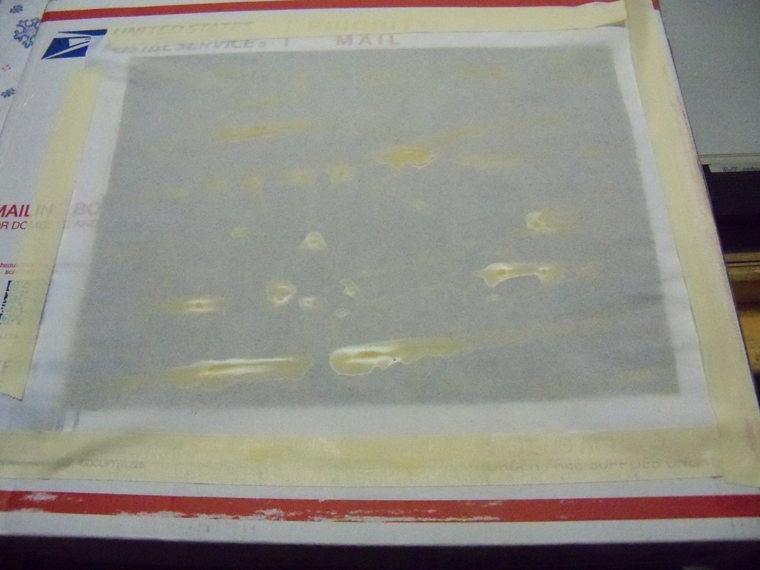
This is a question regarding your simple man's guide to small scale sail making. Do you remember what ratio of PVA to water you used for the Witches Brew sail wash? You described it as being the consistency of milk, but would that be skim, 1%,2% or whole milk? I'm making sails for my 1:96 scale Phantom pilot boat and when the material dried overnight, the mix apparently pooled in the low spots and drained from the high spots as shown below which made the finish very uneven. I'm not sure if it was my mix or the light weight drafting vellum paper that I used. I don't know for sure, but maybe I should have used your hurry up method of using a hair drier to speed it up. As light as the vellum paper was, maybe it was still a bit too stiff. I found some very light weight tracing paper that I will try next.

-
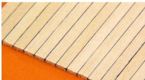
Well Roger, for some more authentic-looking (because the grain varies from plank to plank) wooden model ship decking or board-by-board siding go to Micro-Mark. Black glue is used to bond individual planks of basswood together side-by-side in sheets 3 inches wide x 22 inches long x 0.050 inch thick, perfectly simulating the look of board-by-board construction without the tedious, time-consuming hassle of doing it yourself. Planks widths are available in 1/16 inch, 3/32 inch, 1/8 inch, or 3/16 inch. The price is around $25 per sheet. Have a look here.
-
Good question! The plans for the MS Phantom show one of these also. No details are provided there either.
- 397 replies
-
- 1
-

-
- cutty sark
- revell
- (and 2 more)
-
A big miss in only 42 to 48 hours
BETAQDAVE replied to DaveBaxt's topic in How to use the MSW forum - **NO MODELING CONTENT**
I just went through this posting and happily found out that it wasn't due to something I did on my end. I still remember the old Computers for Dummies manuals which emphatically declared that your computer won't blow up if you push the wrong button. Yes, but other bad things definitely could and in my case did! 🙈🙉🙊 -
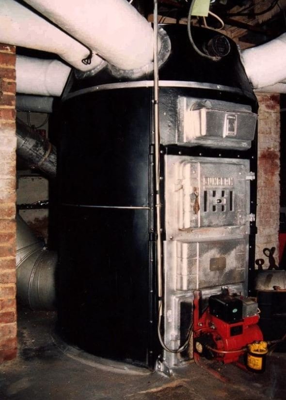
Speaking of Dodgy furnaces: My maternal grandparents lived in a three flat building built in the early 1920’s. They had a coal burning gravity hot air type octopus furnace similar to the one below, but without the red accessory that was later added on at the bottom. There was no fan to force the air up since the hot air just naturally rose through the ducts. Each heating vent had it’s own duct that attached directly to the furnace and made it look like an upside down octopus. The building had more than a dozen heat ducts and due to that maze of ducts and the large coal bin, it took up most of the basement. The basement ceiling was also about twelve feet high to allow some clearance below the ducts. Access to the basement was by a 22 rise L shaped stair with a landing half way down that was in a separate room partitioned off from the furnace room with a large heavy steel door, with a closer that always slammed with a resounding bang! I say that because, to a group of young kids ages 3-5 it made us all jump whenever it closed behind leaving us in what seemed like a dimly lit dungeon. Eventually we became more adventurous and started going down there to play, but our parents began to worry about us getting into mischief way down there, so grandfather, who always was a bit of a prankster, teased us that there was a green eyed monster that hid in the coal bin sometimes to discourage our interest in going down there. At first, we began to think that he was just kidding us since we never saw it and started to go down there again anyway. So grandfather decided that now he needed up his game a bit. Taking a pair of flashlights with some green cellophane covering the lenses, he turned them on and placed them in the coal bin just before our next visit. So when we were about to go down to the basement, he told us that he had just seen the green eyed monster in the coal bin earlier and we probably shouldn’t go down there. Of course we all though he was just teasing us again, but he said that he better go down with us to see if it was still there. Well, we had just entered the furnace room, he ushered us inside and closed the door with a bang which set us a bit on edge to begin with and we looked around somewhat nervously and said we didn’t see anything. Now the basement, with its one small window and a single light bulb, was pretty dim down there to begin with, but he suggested that we might be able to sneak up on it better if we turned out the light,. So he did. Walking over to the coal bin he opened the door a bit and we all looked in. Lo and behold, there was this pair of bright green eyes starring right back at us!! 👾😱😲 We all instantly made a panicked run to the door and flew up those stairs as fast as we could! For years after that we never went back down there unless grandfather checked it out first.
-
So I guess that professional golfer John Daly styling would not be accepted?


-
Concerning post #49 I think that something like this has been developed, but his aim would be a little iffy.

-
That's so he can protect himself from being poked in the eye from the projecting spars and rigging.
-
But, on the bright side, he is wearing safety goggles!
-
Or more likely, some of the stuff that we somehow survived to get old.
-
Sounds like a method of suicide by self strangulation to me.
-
I just added the topic Alternate Definitions twice in error, I think once would be sufficient. The second one needs to be deleted.
-
a drafting tool or paper weight
BETAQDAVE replied to garyshipwright's topic in Modeling tools and Workshop Equipment
It's actually a drafting tool. Several of these hold a flexible spline in place and used for drawing curves. -
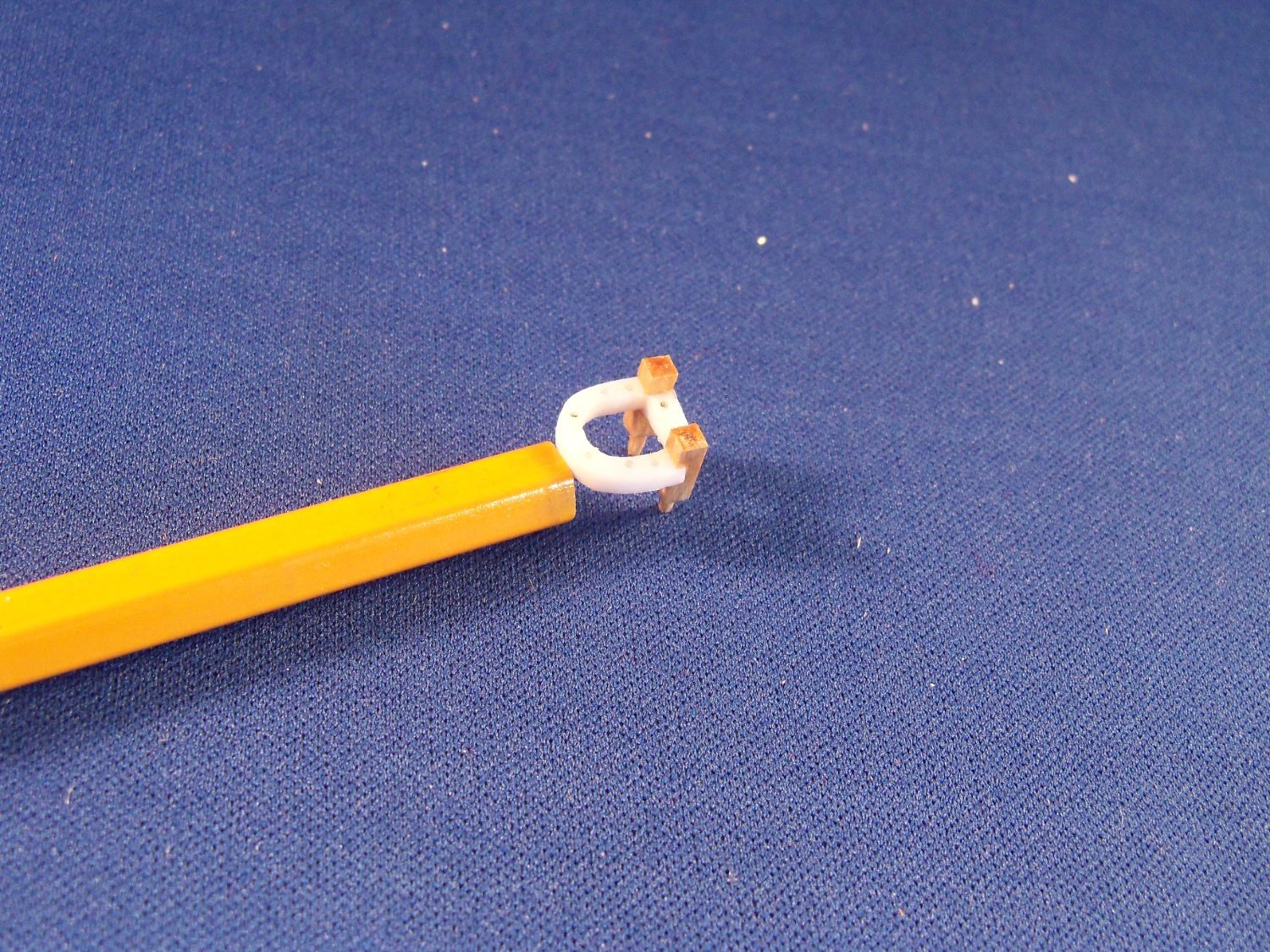
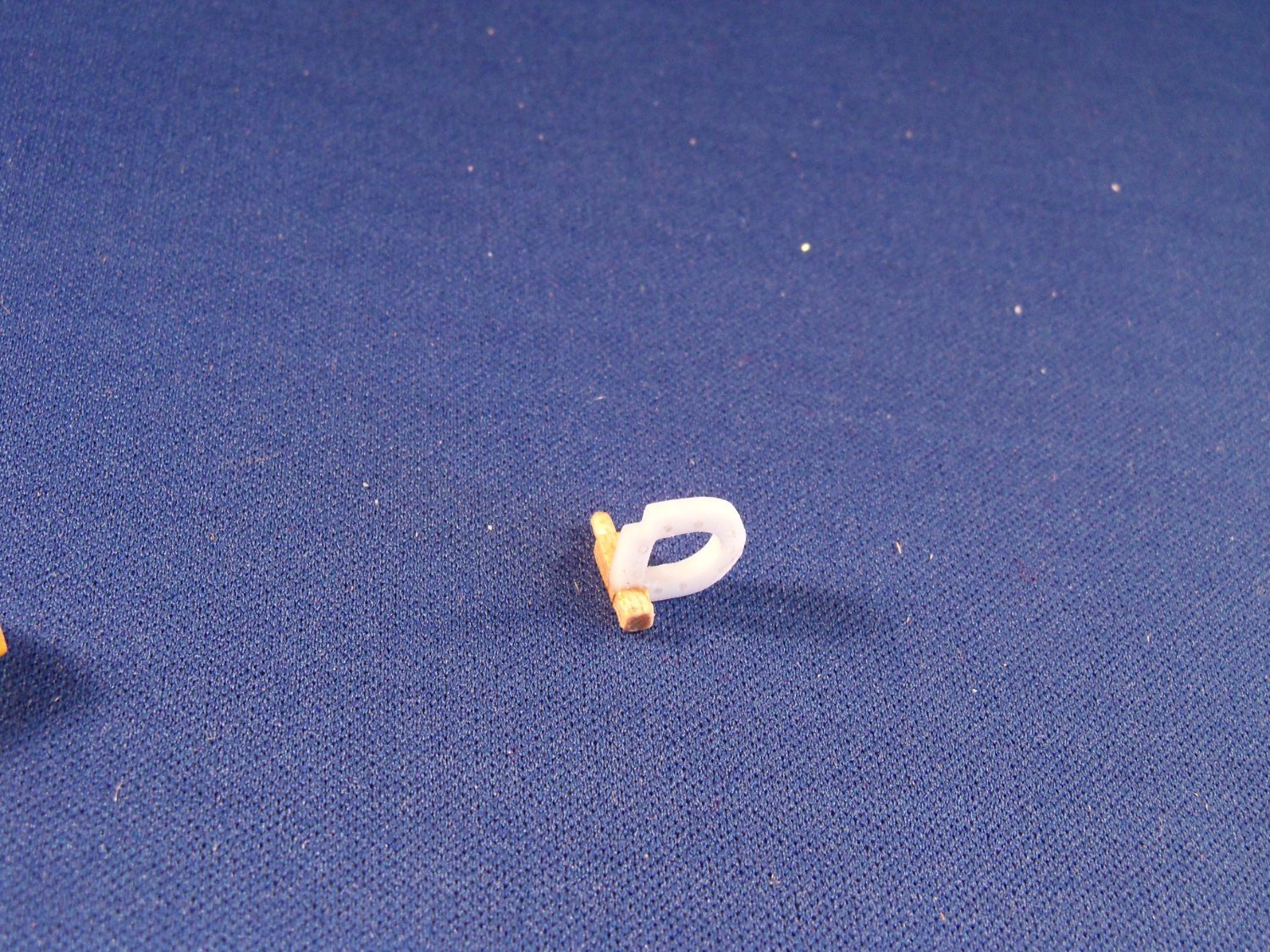
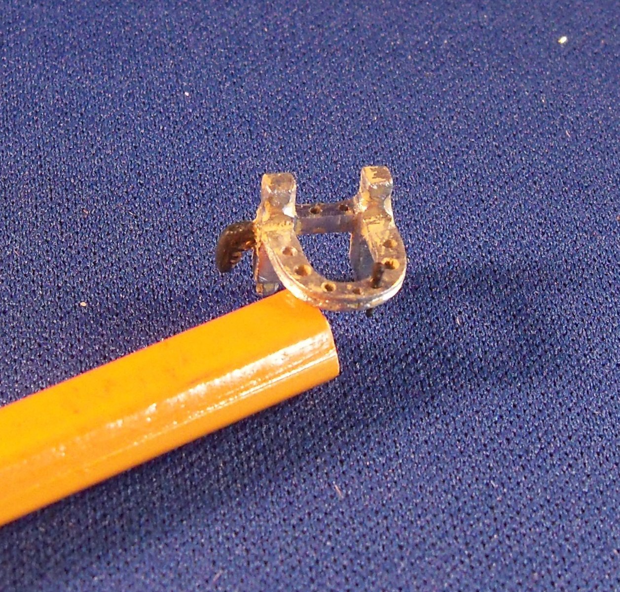
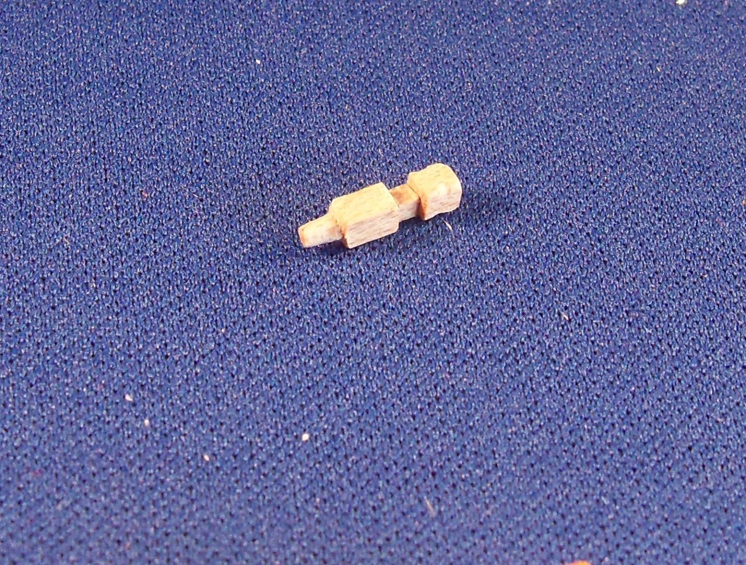
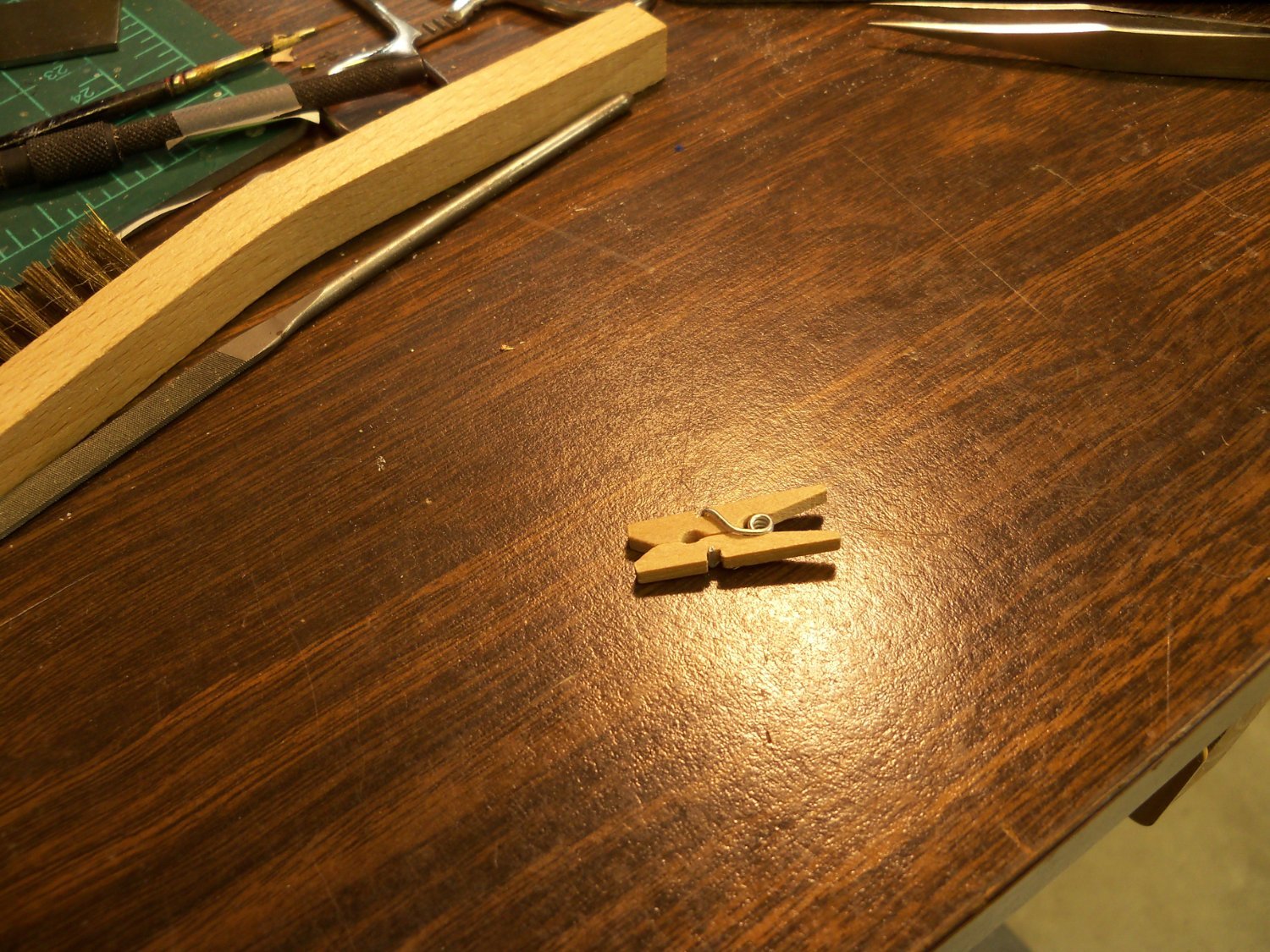
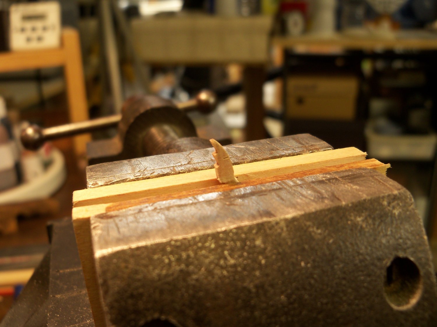
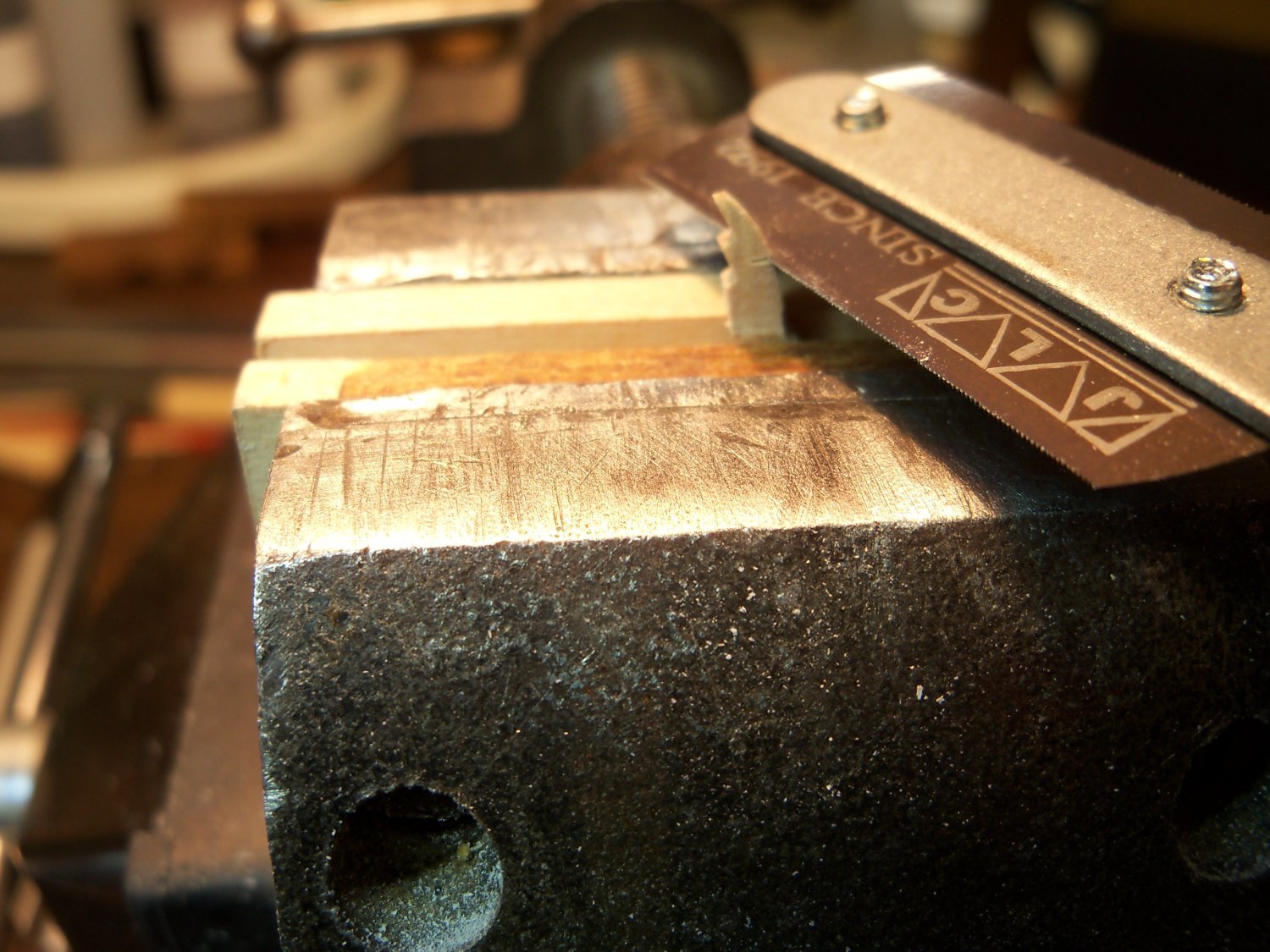
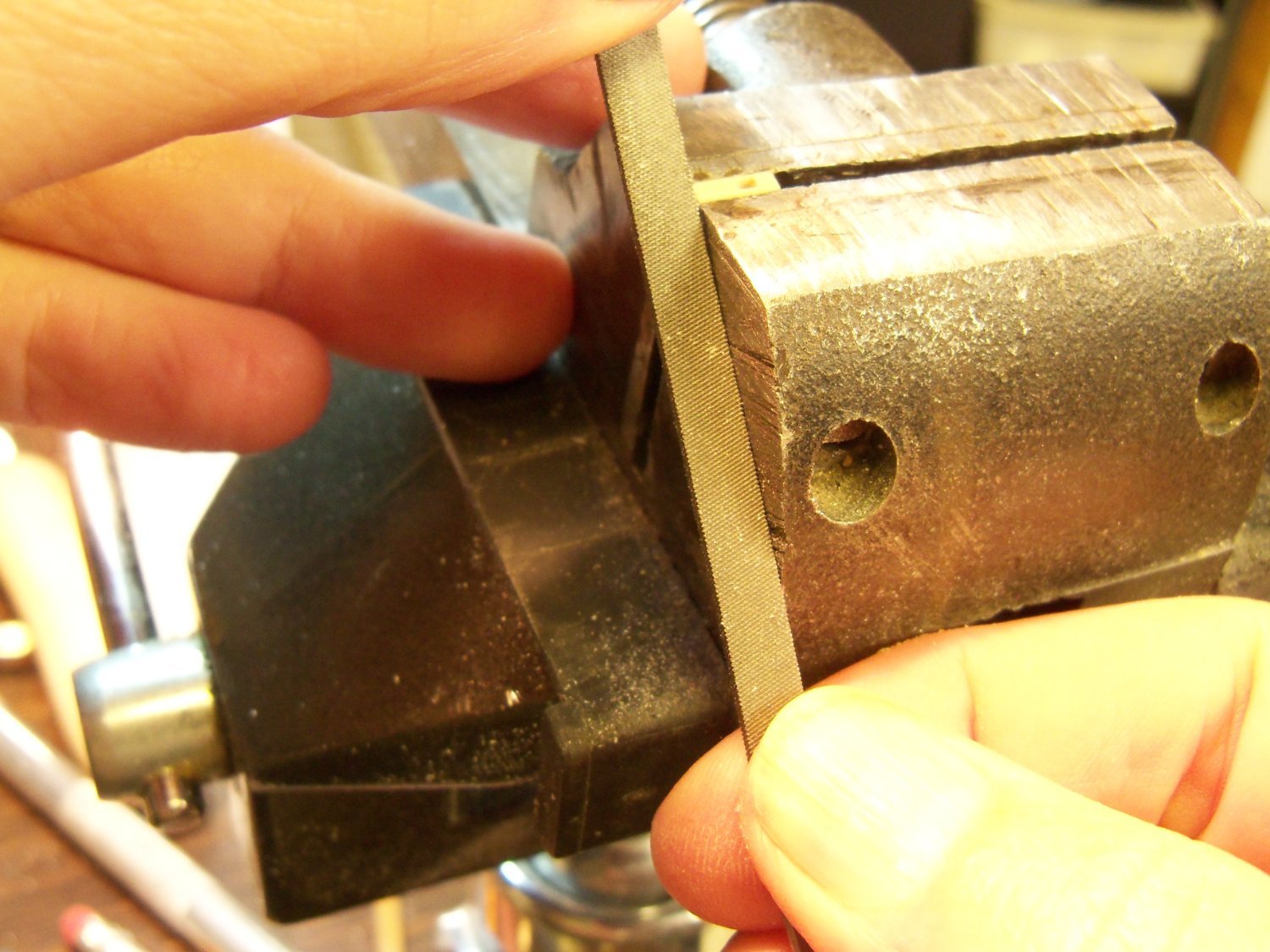
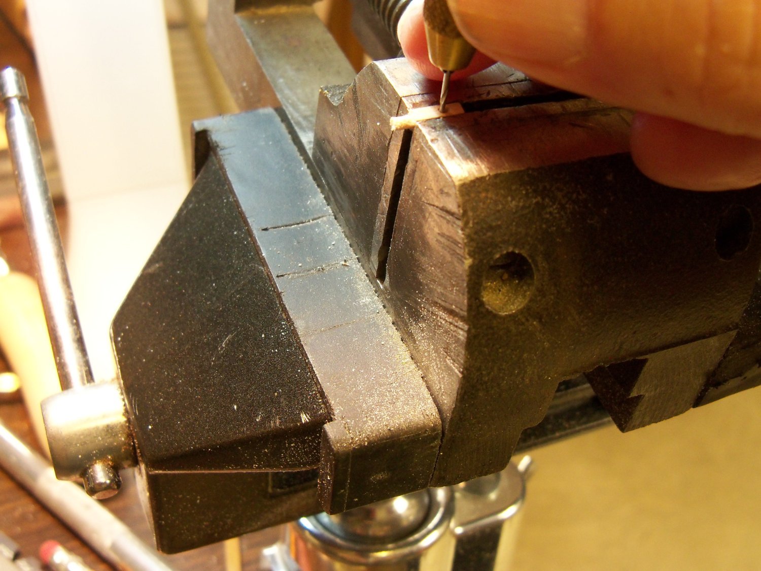
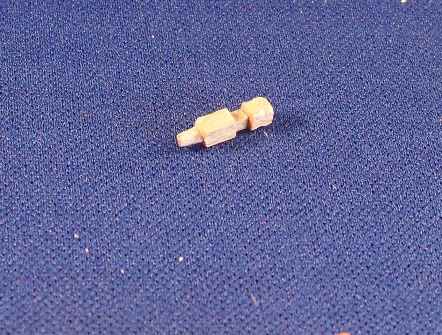
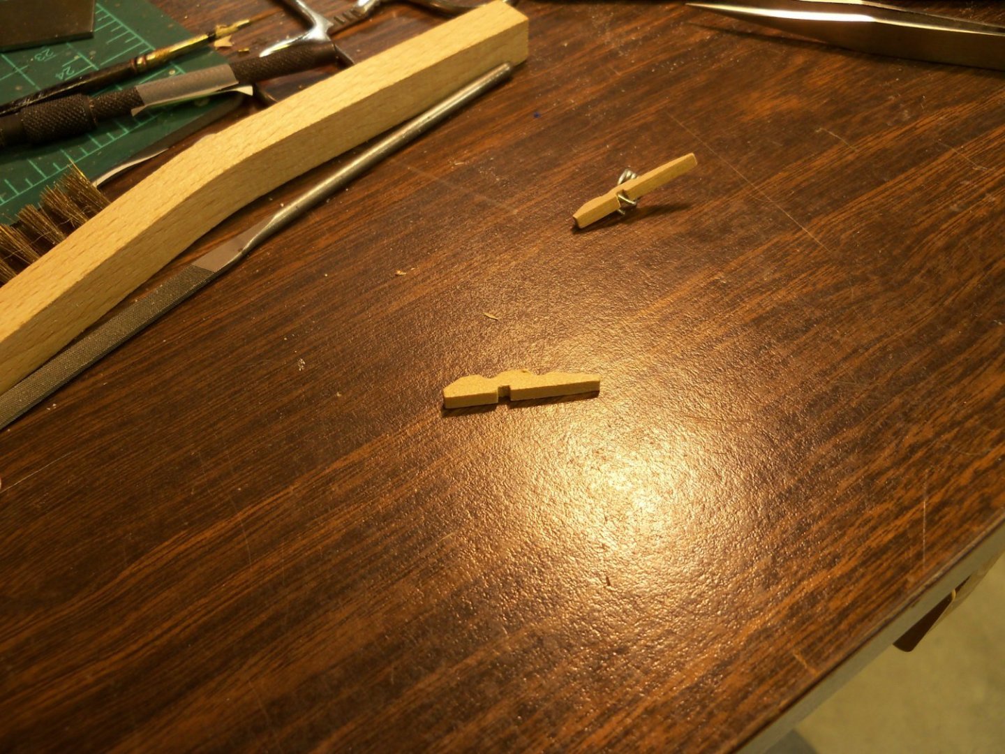
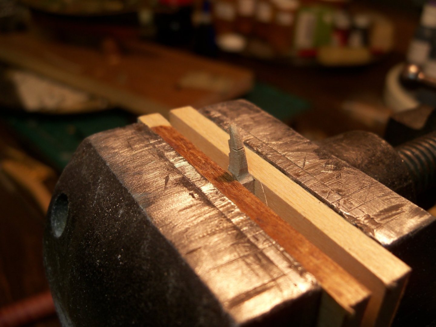
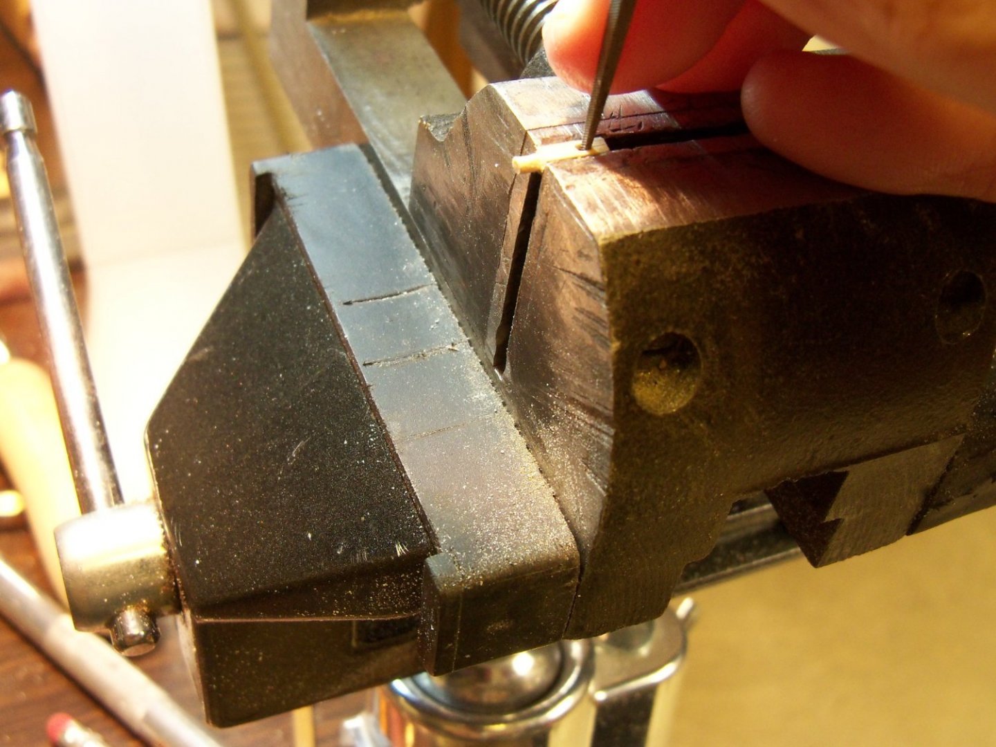
The metal fife rails that came with the kit shown below didn’t look much better than the kit supplied anchor so I decided to see if I could do better job with wood. They also differed both, from the detail drawings on the plans and the ones shown in Chucks’ practicum shown here. You can see that the cross bar between the posts and the side half cleat are higher than the fife rail on Chucks’, as opposed to them being even on my kit and the details. The posts are taller than mine, and the spindles are much thicker. The belaying pins included with the kit were much too short to project below the rail which would not allow the belayed lines to be tied off. The first step was to rip a 3/32” X 3/32” maple strip about 6” long for the post material. I marked one face for the cuts and using my Micro Miter Box with the ultra-fine toothed double-edge razor blade once again, I cut it into six sticks about 1” long. In this case, the final length was 7/16”, leaving 9/16” left over to hang onto during the machining. Since this was another process of making each piece an exact duplicate of the others, I utilized the adjustable stop for every cut. The stop was not reset until that particular cut was repeated on every piece. The first cuts were made 3/64” deep and 7/64” down from the top of the post on two adjacent sides. The next two cuts were duplicated 1/16” below the first cuts. Clamping each post in my machinist vise, I carved out a 3/64” deep notch between those two adjacent sides with a fine file between the first two cuts for holding the fife rail. Returning to the Miter Box, a very shallow cut was made on all four sides of the stick 21/64” down from the top of the post to mark the overall height of the post above the deck. 7/64” below that cut, the post was finally cut loose from the stick. Now each post was clamped in my vise with the 7/64” bottom left exposed. Once again I filed a round peg with files and sanding sticks for insertion into the deck. Here is one of the resulting fife rail posts. Then I also needed to make two throat halliard half cleats to be attached to the posts. There is one on the starboard side of the main fife rail and one on the port side of the fore fife rail. I decided to carve these from wood, since cutting one of the kits’ metal ones in half would still be over-sized. These cleats are a prime example of fabricating extremely tiny parts, (1/16” wide X 5/64” high X 5/32” long) so I will provide some photos of the process here. To start with, I sacrificed these hardwood clothes pins for the material as shown below. The long skinny portion was clamped in my vice, leaving the short fat end exposed. Using sanding sticks and files, the top and bottom were shaped. Once the top and bottom of the cleat were shaped, the sides of the cleat were thinned down and tapered to the final profile. Now that the main portion of the cleat was finished I released it from the handle with that razor toothed hand saw and repeated the process for the other cleat. The cleats will be painted iron black and glued to the appropriate fife rail post.


-
My metal ruler was wrong.
BETAQDAVE replied to modeller_masa's topic in Modeling tools and Workshop Equipment
That's opposed to using elite and pica typewriters, where elite was 12 characters per inch and pica was 10. I always thought that 1/6th scale was a peculiar system of measurement to be used for modeling when I had to build my first model of the Wanderer from the A.J. Fisher plans. I had to make a custom ruler just to build it. Luckily, they had the fittings kit that matched. -
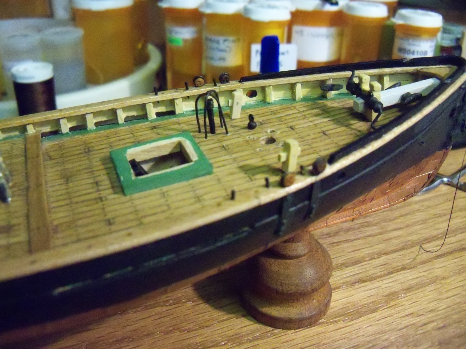
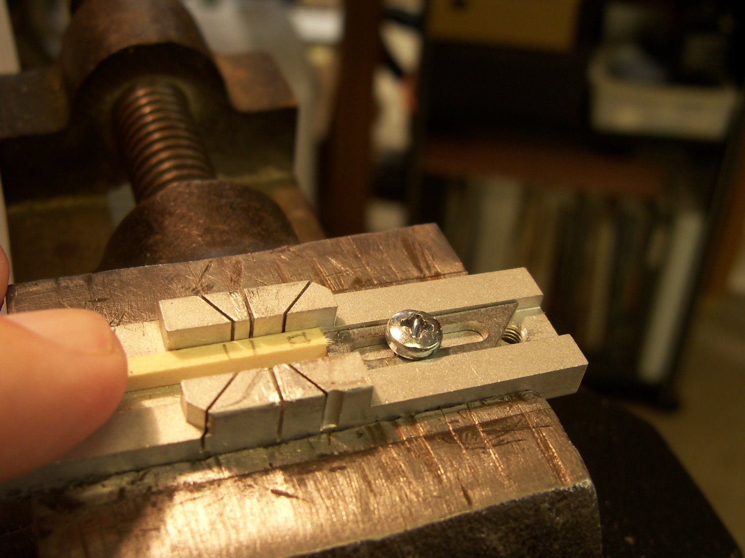
I decided to tackle the bollards next since they seemed to be a simpler project. The ones I made previously appeared over-sized when placed on the model, so these were now discarded. Originally, two posts were made with a rectangular cross bar and the other two were without. This time, all four will have the cross bar. Since these posts wouldn’t be under any strain once installed, I just used six 2” lengths of 3/32” square basswood stock for the new posts. (I’ve learned the hard way, that small pieces need to be cut overlong to leave a “handle” until cutting the piece loose and to make extras.) To be uniform, I made extensive use of the stop on the Micro Miter Box below for all of the cuts and made the same cut on each piece before moving on to the next piece. On the face of the first post, marks were drawn at the locations of the top, bottom and sides of the mortise for the cross bar, the height above the deck and the overall length of the piece to serve as a pattern. The mortise is centered and 1/16” down from the top of the post. The mark for the deck is 1/4” below the top of the post and the overall length is 7/16”. The cross bar is made from 1/32” X 1/16” maple and is cut overlong at 1”. The first cut in the post was a shallow one all the way around the post at the top of the deck mark to limit the filing of the peg. The next cut was to separate the post from the rest of the stick. The post was set in the vise with the shallow cut up against edge of the vise as shown below to allow the use of a flat file to form the peg at the bottom that will be set into the deck. The mortise was formed next by putting the post in the vice to prevent it from splitting while forming the hole. Two side by side 1/32” through holes were drilled first with a pin vice. Then I used my smallest square file to square the corners of the mortise until the cross bar was a tight fit. The cross bar was inserted into the mortise until it projected 1/16” from the opposite face of the bollard. The remaining end of the cross bar was also trimmed off leaving a 1/16” projection with a fine sanding disc mounted in my cordless Dremel tool. Once the cross bar was in place, I used a #78 bit to drill through the post and the bar joint. I sliced a tiny sliver of wood and inserted it through the hole to lock the joint. Here are photos of the four bollards put in place on the model. There was some thought of putting a copper cap on the tops of the bollards again, but after a little more research I found that it was not all that common a practice on pilot boats. Besides that, I would have to put a cap on all the vertical posts to be uniform. The completed bollards were sanded, given a light coat of light buff deckhouse and set aside for installation later. Next on my list is the fife rails.


-
Welcome to the clubs John, both MSW and the Phantom build club. Many of our members have tackled this kit as one of their first wooden ships. Originally I bought this kit as a graduation gift for my uncles son while it was on sale. Unfortunately, (Or maybe fortunately) I discovered by way of my uncle, that he didn’t think that his son would be interested, so we ended up just giving him money instead. Since it had been quite a while since I last built a wooden ship, I decided to tackle it myself. Chuck Passaro made a build log that pretty much follows the kits’ manual. I would suggest that you read his log first since his guide goes from the beginning to completion of the model. I have deviated quite a bit from his version, but it was mostly to add things that the kits’ manual either over simplified or omitted all together. My only regret that I have is that I forgot how hard working at this small scale was. I think I would have preferred making it from scratch at 1:64 which would have made all of the tiny parts much easier to handle and add the smaller details, but perhaps I could do that later, if I hang around that long. At any rate, I continue to soldier on with it and switch over to the Wanderer whenever I feel the need for a little more variety in the hobby. As far my Wanderer build goes, the vast majority of the plastic parts I will be making myself since those parts are inaccurate and/or poorly detailed. Good luck on your build, and don’t be afraid to deviate as you see fit.
-
I've found conflicting information on late 19th century timber bollards. While most bollards were simply bare topped timbers, some had metal or leather caps apparently to provide protection from end grain rot. For one example, in the whaling industry there was a large vertical bollard that the cutting in gear was secured to that usually had a metal top applied to it. It may also have served as an anvil for the ships carpenter. Has anyone else come across any info. on this?
- 1 reply
-
- 2
-
-
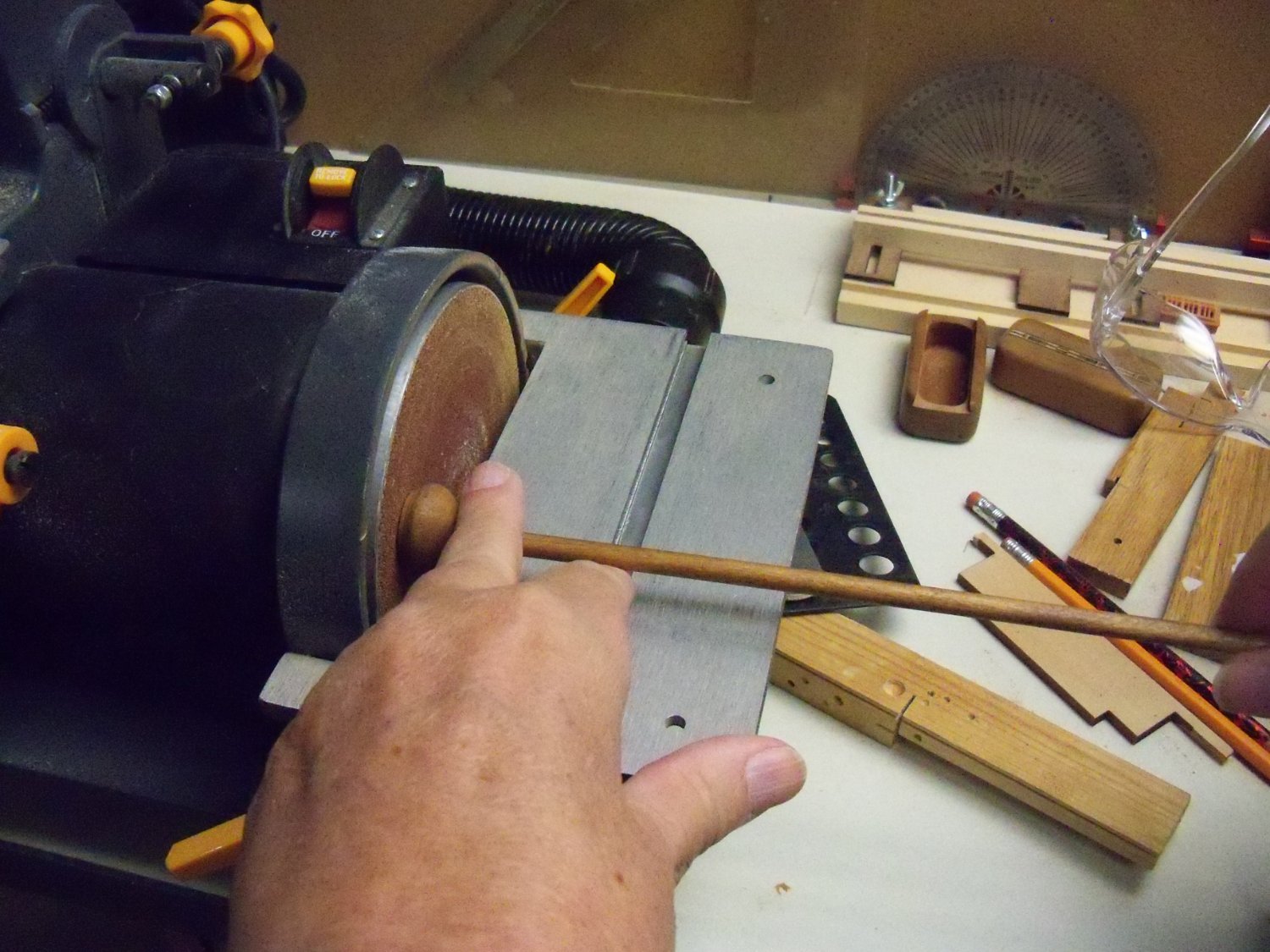
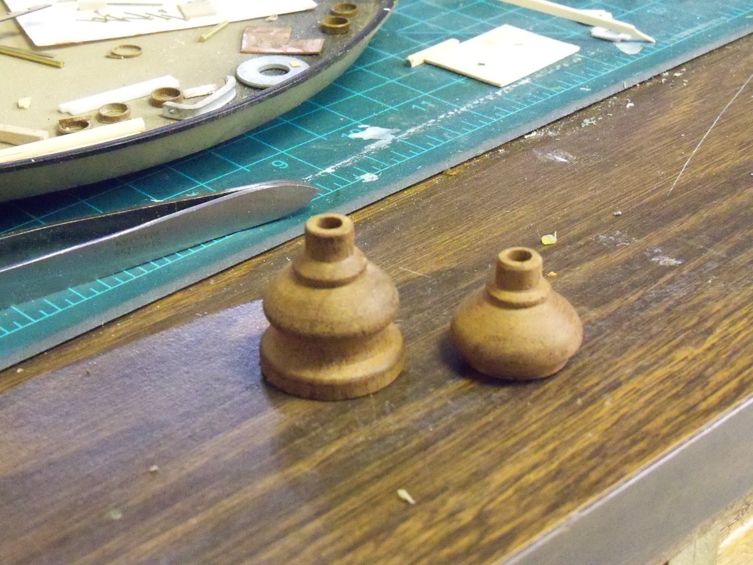
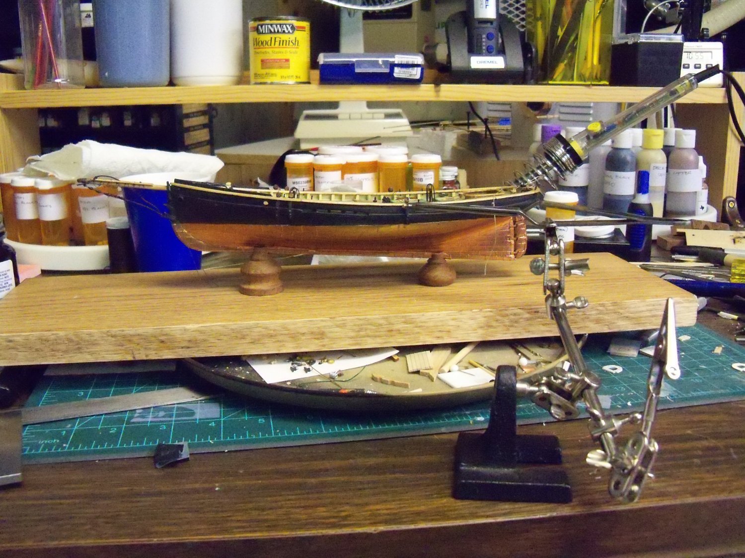
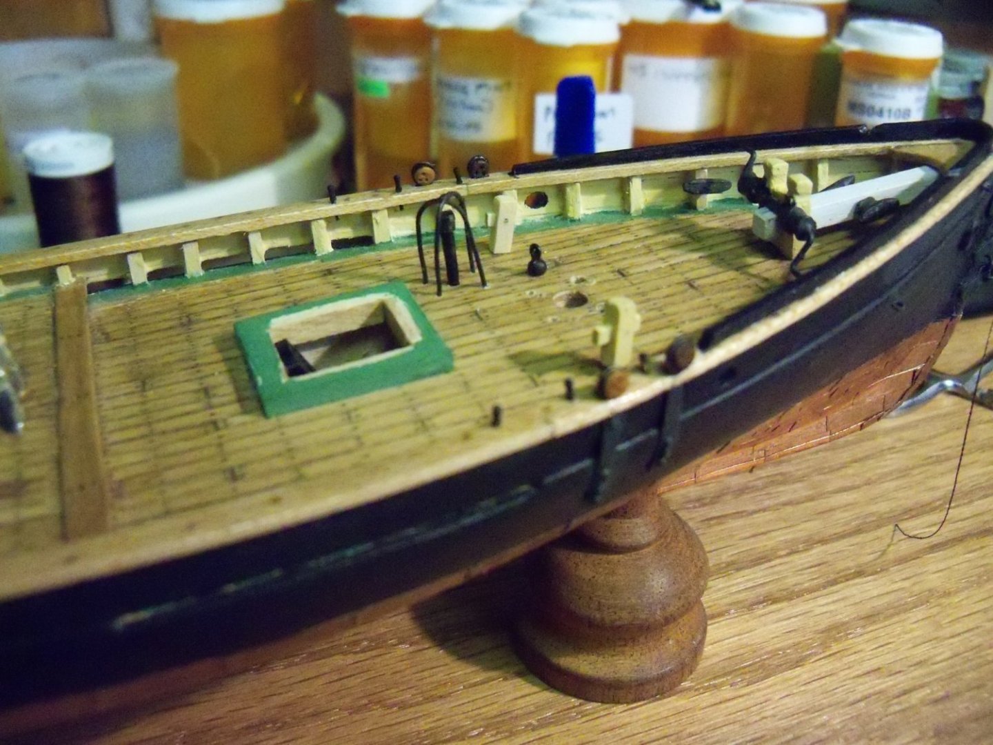
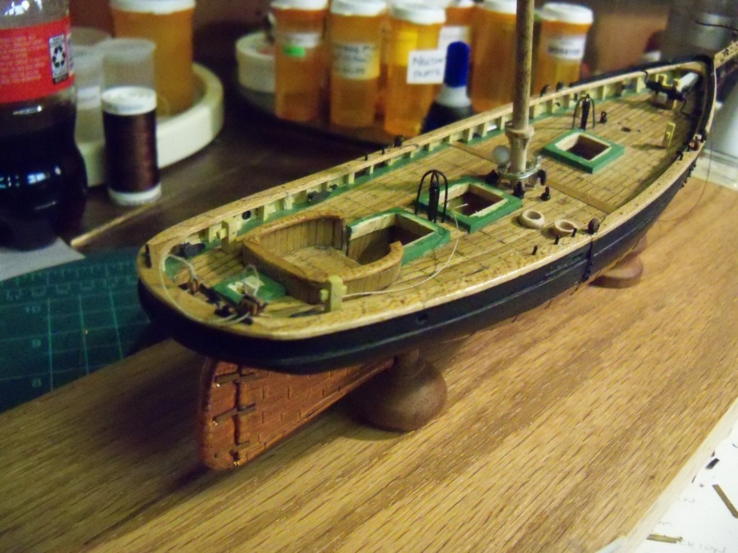
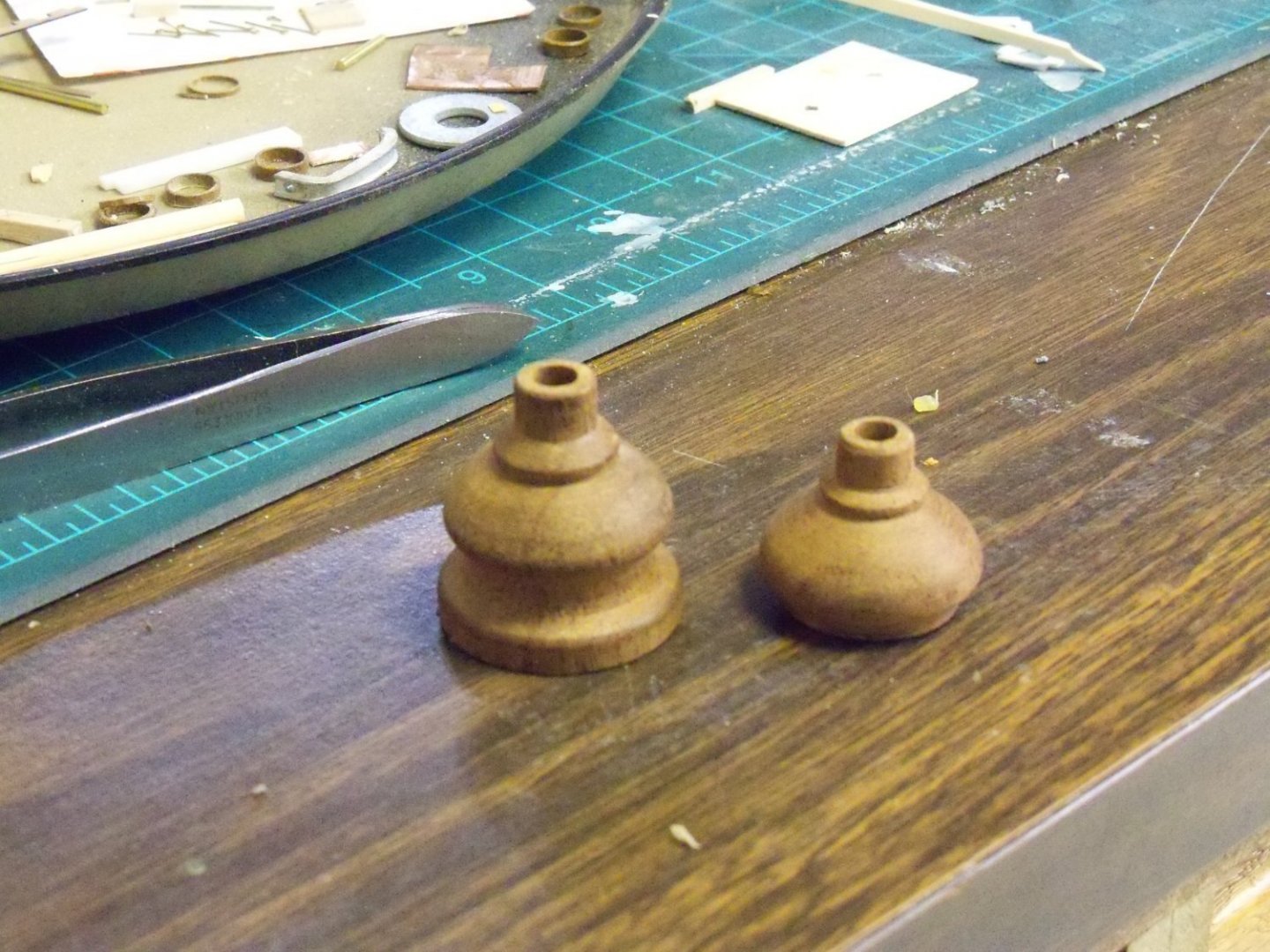
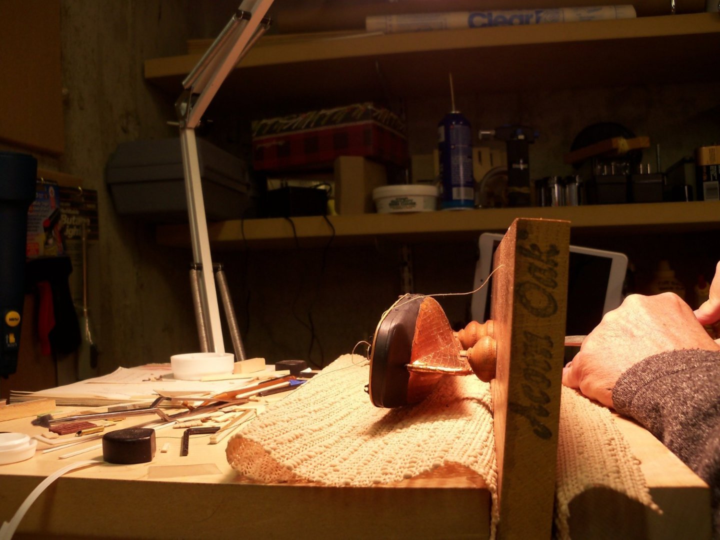
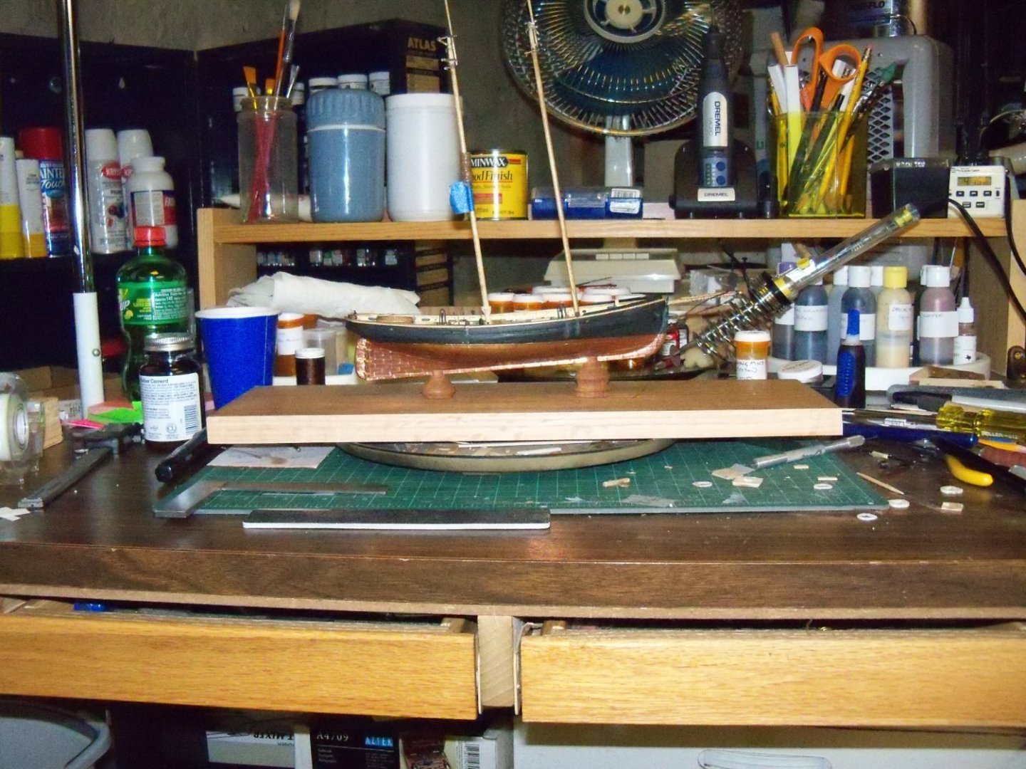
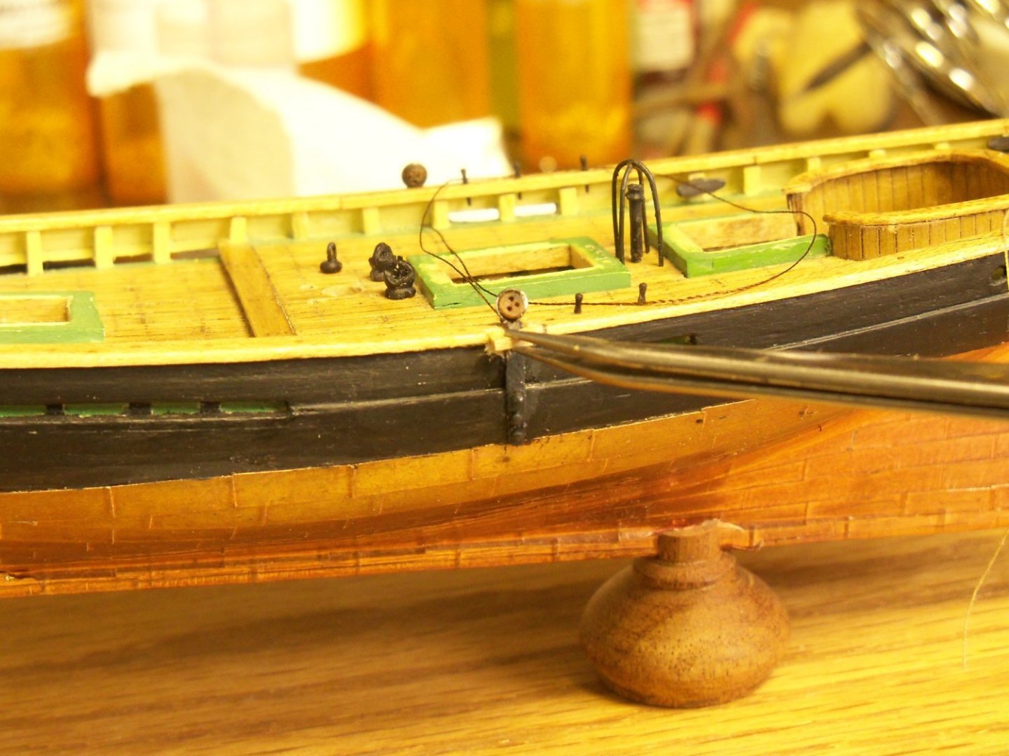
Heading out to my scrap lumber supply in the garage, I pulled out a 15” long piece of 1X8 prefinished oak to rip down to 5” wide for the display base only to discover that my table saw is out of commission right now, since one of the rubber caster wheels had been crushed by the weight of the saw. So the band saw had to be used instead. Since the band saw gives me a rougher cut than the table saw, I also had to use a heavy hand plane to smooth it down. I measured the plan to determine the placement of the support pedestals and marked the location of the holes on the display board. The ends of the board will still need trimming and a rabbet needs to be formed all the way around the board to hold the plexiglass cover, but I will have to do all of that at a later time. OOPS! I thought things were going too smoothly and I was right. 😢 While handling the hull to temporarily set it upside down on the drill press to drill the mounting holes in the keel, I inadvertently broke out a small section of the port side main cap rail right at the lower mainmast deadeye. So now that’s something else I’ll need to repair after getting the ship mounted. The hull was placed upside down on a piece of plywood with some leveling blocks to make the waterline parallel to the plywood. The positions of the two holes 4.5” apart were then marked on the keel at stations #2.5 and 7. The whole setup was put on the drill press table and maneuvered into position below the drill bit. Very carefully, I drilled the 7/64” holes to the proper depth into the keel with a brad pointed bit while trying to avoid damaging the copper plates. Long ago, I had turned a matching pair of pedestals out of walnut for mounting a plastic WWII warship that ended up being made of brass. Rather than order another set of brass pedestals, I decided to modify the walnut ones to suit the sloped keel of the Phantom. First I measured the required height difference in the two pedestals and put a mark there on the lower portion of the short one. By slipping a tight fitting dowel into the mounting screw hole, I went over to my disc sander and held the dowel perpendicular to the disc as shown below. I slowly pushed the pedestal into the disc while rotating the dowel until I came to the mark. Here is the modified pedestal next to the original one at this point. The slots in the tops of the pedestals were cut to fit the width of the copper plated keel and the mounting board was clamped in my padded woodworking vice. Then I laid the model on its side and lined it up with the holes for the screws as shown below. One screw was pushed through the board, the pedestal and into the hole in the keel. Once this one was started, I did the same with the other screw and alternated from one to the other until both were secured. I inserted the masts just to be sure it was vertical and here she is temporarily mounted on the board. Now that the model was on a stable base, it was time to make my repair of the damaged cap rail. The damage was only about 1/8” long, but that’s what made it so difficult to fix. I had to take a file to the remaining portion of the cap rail so I could form a less ragged replacement piece and remove the finish to allow the glue to have something to grip. I used a scrap of 1/32” thick maple, a bit wider than needed, to leave me something to grip with a hemostat while machining it. The ends were trimmed to match and a notch was filed in the joining edge to go around the deadeye strop. Once it was shaped to fit snugly into the gap, I clamped the hemostat in one arm of my triple grip third hand as shown below. Adjusting the orientation of my patch to align with the model in the base, it was slid aside to allow me to carefully apply some carpenters glue to both the model and my patch. Sliding the third hand back into position, I carefully backed away from it and left it to dry. Having left it undisturbed for two days, the clamp was removed, and although it still projected beyond the edge of the cap, I found it to be securely attached. So, using some fine files and a very fine grit sanding disc in my cordless Dremel tool, the edge was trimmed back flush with the existing cap. Since my Dremel tool only required a light touch, I thought that it wouldn’t break off the patch. That’s why it did the majority of the stock removal. Refinishing the patch and the area around it with polyurethane, I found that only close examination would reveal the repair. Who could ask for more? I’m not sure what to tackle next, as my table saw in the very cold 🥶 garage will be out of commission now until things warm up to allow me to repair the crushed caster. I don’t want to keep taking the model off the base anymore than necessary as the grip of the mounting screws will loosen and I don’t want to install the masts and rigging until it is permanently mounted. Perhaps I will work on finishing some of the deck fittings like the fife rails since the metal ones don’t look that great to me anyway. I think that the bollards that I made look too big, and will be redone also.


-
vacuum for power tools
BETAQDAVE replied to Don Quixote's topic in Modeling tools and Workshop Equipment
Generally, the more bends, splitters and other fitting you add, the less suction you get.