HOLIDAY DONATION DRIVE - SUPPORT MSW - DO YOUR PART TO KEEP THIS GREAT FORUM GOING! (Only 20 donations so far - C'mon guys!)
×


allanyed
-
Posts
8,149 -
Joined
-
Last visited
Content Type
Profiles
Forums
Gallery
Events
Everything posted by allanyed
-
Hello Dan, Welcome to the fray. It is great place to share and learn, enjoy the ride. Allan
-
 Before spending even a little money, I am very interested in the accuracy of this book. Does anyone one know what sources Mr. Kirsch used? To what detail does he go and does it cover galleons from Spain, England or?????? Many thanks in advance. Allan
 -
Love it Dean!!
-
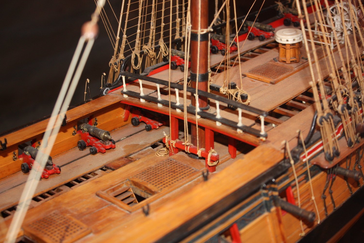
The copper plating is impressive as it looks realistic compared to the ones that look like they are held on with giant rivets. Really nice work. Your rudder gudgeons and pintles look to be to scale which is great. Not all kits are accurate when it comes to these rudder parts and yours look really good. Just as an FYI, the Admiralty did not allow the names on the sterns of RN ships except from about 1781 to 1790. As Pegasus was launched in 1776 and was lost 10 months later she probably would not have her name on the stern. Were there exceptions? Maybe, as there are a couple contemporary models and plans (Bristol 1775 is an example) outside that time period with their name on the stern. Even in these cases I have some doubts that the ship itself had the name as it was Admiralty orders not to. Then again artist license applies though for our models.😀 Allan
- 254 replies
-
- 4
-

-

-
- Victory Models
- Pegasus
- (and 3 more)
-
Hi Dean Sorry for the miscommunication. I was not suggesting anyone must follow the construction, I was asking about the correct interpretation of the drawing. Is it indicating scarphs or something else? As to including hidden details, I am with David, put 'em in if you want to, leave 'em out if you don't. I have done both and feel good about both. Even an in between with the partially planked decks to show a few of the carlings and lintels and maybe a peek at the stove and such is an option as you mentioned. David, regarding tree nailing decks I would go farther and say that, for me, the use of these has ruined a lot more otherwise really nice models than they ever enhanced. But, as you so eloquently stated en français, chacun à son goût! Allan
-
Huw Is your post an offer to sell your boxwood? Allan
-
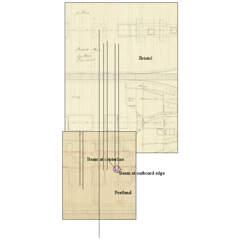
A few of us have looked at these drawings and are of the opinion that the drawing of the beam ends in elevation indicate lips of the scarphs. This was new for us so would be interested to hear others' opinions as to what the circled area indicate, offsets of the scarphs or something else. Note that the Bristol (50) has no scarphs on the orlop beams where as the Portland (50) may, if the offsets shown are indeed scarphs. Hard to see on the JPG but pretty clear on the PDF that follows. Allan Beam question.PDF
-
Chuck, Thanks!! I was going to ask if small vessels like cutters would have had a false keel so thanks for pointing this out😀 In the case of Cheerful was it because the keel does not sit flat but rises fore and aft (ZAZ6467), or, ships' boats aside, was having no false keel typical for cutters and similar size vessels? Thanks again. Allan
-
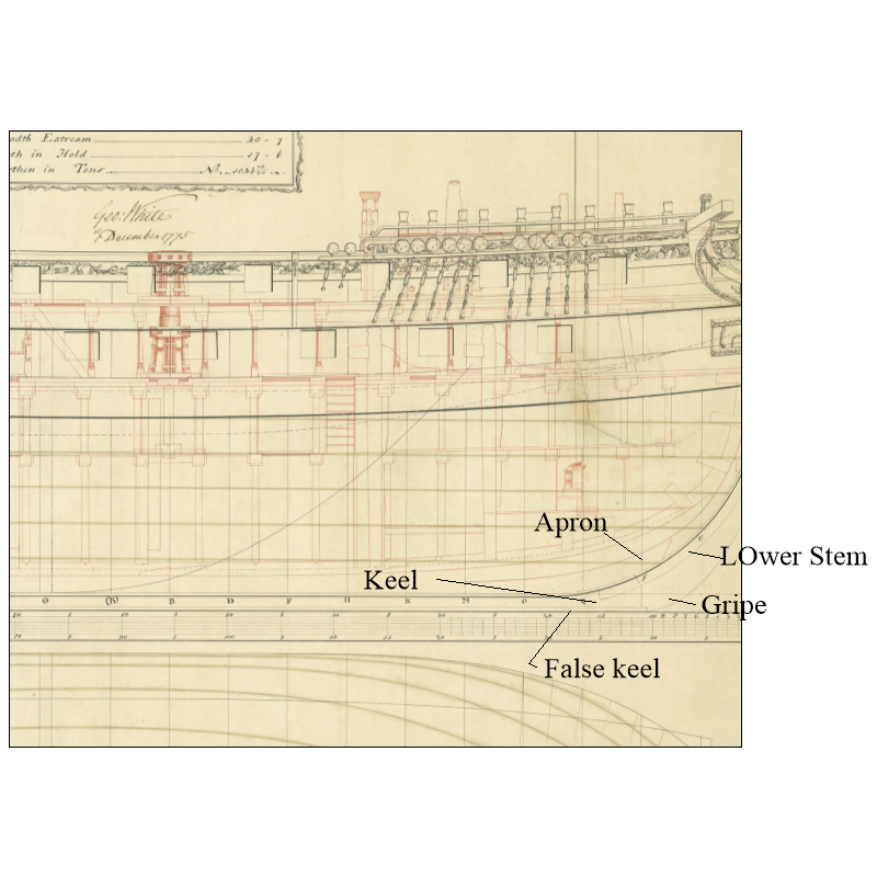
Glenn is correct. One more drawing regarding terminology showing HMS Bristol (50) in png and pdf. PDF is much more clear. Allan Keel, false keel, etc..PDF
-
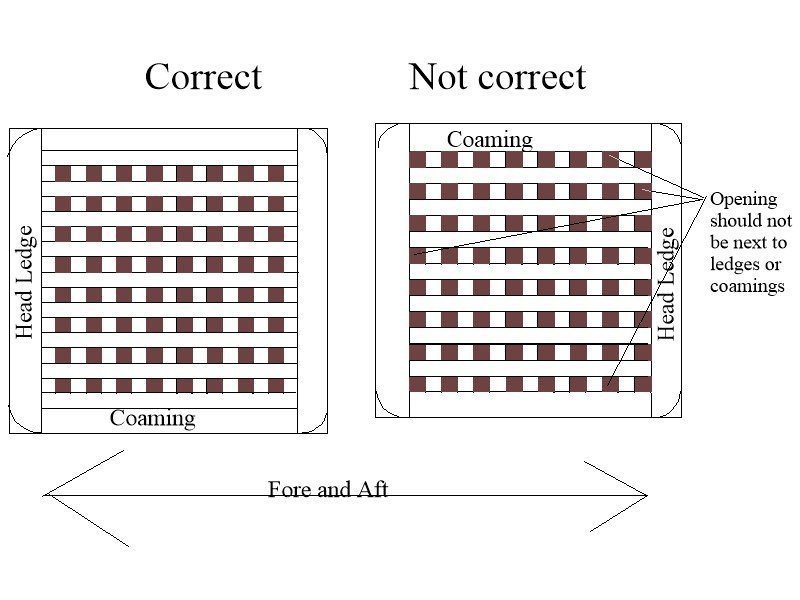
Your gratings look nice. One trick I went to years ago to be sure there are no openings against one or more of the head ledges or coamings is to finish the grating so it is a solid band on all four sides as close to the plan dimensions as possible, then make the surrounding timber of head ledges and coamings to fit the grating, not the other way around. Picture & a thousand words, etc. below Allan
- 49 replies
-
- 5
-
-
- Pegasus
- Victory Models
- (and 1 more)
-
As time is sometimes part of your equation, the hot air gun will save hours. The Galaxy Pro should suffice and can be found on Amazon UK for a reasonable price. https://www.amazon.co.uk/s?k=hOT+AIR+guns&crid=O6BKDLLKMS3T&sprefix=hot+air+guns%2Caps%2C198&ref=nb_sb_noss_1 Allan
-
HI David The frames were routinely cut for the gun ports so there is little danger from cutting too many. For example the Portland (50) 1770 is typical in that it had 50 frames cut short on each side to accommodate the gun ports on the various decks. The Impregnable (98) 1810 had frames cut short in 106 places on each side for the entry port and gun ports. Allan
-
Sounds like Paul solved the problem, but there is no false keel in your photo, just the keel and the piece with slots for the bulkheads above the keel so it was confusing when first reading your post. Most likely a terminology issue and happy the problem was solved. Allan
-
Tim, Self discipline is about all I can think of. If things are not going right for me, it's usually because I am rushing and in the end it takes less time to do it right one time than to do it more than once because it was a mess up the first go around. Allan
-
Retrofit ship columns
allanyed replied to snedley22's topic in Building, Framing, Planking and plating a ships hull and deck
Hi Snedley 4mm equates to 14 inches which seems to be much too large to be realistic on every deck. While not Spanish, but based on scantlings from the Shipbuilder's Repository 1788 a first rate of 110 guns had pillars in the hold for the gun deck that were 9.5 inches X 9.5inches, less than 3mm at your scale and they get smaller as you go up. For the pillars under the middle deck they were 7.75 inches across at the top and 8.75 inches at the bottom. For those under the upper deck, they were 7" at the top and 8" at the bottom so about 2.5mm. If yours are typical the largest pillars will be square or close to square for about 10 inches at the top and 12-14 inches at the bottom then round in between. They may be a bit fancier on some decks which means using a lathe. If the simpler design was used, get square stock of the appropriate sizes and you can easily carve the cylindrical portion with a simple carving knife or chisel and sand paper. The center portion was often more of an octagonal shape rather than round so very easy to make your own with a carving knife or file. Note that the pillars were a bit larger by 1800 but only the beams in the hold were close to 14 inches (4mm). The others were much smaller in cross section. Allan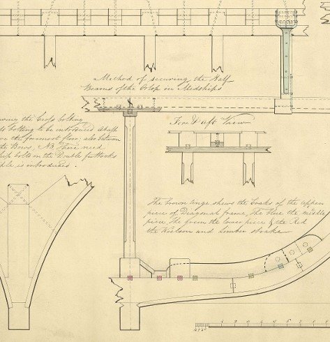
-
Hi Tim, My gun has about a one inch opening with 6 settings for the temperature and to date I have had no problems. The highest setting will scorch the wood so I stay just below that point. I prefer to pre-form the pieces off the hull by spiling or hot edge bending when possible but have had times at the stern where I find it easier to form it on the hull and heat/dry it while it is temporarily clamped in place and have not had any issues. Even then, once it is apparently dry I remove it for some hours or more to be sure it is completely dry before gluing it as it will contract if it is at all wet and leave unsightly gaps. This may only be me, but I have never found speed to be a consideration as I assume a fully framed hull will approach 1000 hours and POB several hundred hours to get things right. If speed was a criterion for me I would not consider ship modeling as a good choice of hobbies, but that is just me. Everyone has their own priorities, so go with what makes you happy which is one of reasons we have hobbies. 😀 Allan
-
Good point Alan. I was taught that it was painted/coated but do not recall where I got that information. I checked in Goodwin's Construction and Fitting of English Ships of War and he states that the canvas was coated with tar, not paint, to make it waterproof. Unfortunately he does not give a reference and I cannot find any other reference regarding this cover so even though he is a single source, it may be valid. I do notice that on contemporary models the cover is very dark compared to canvas. Allan
-
Try soaking the plank overnight and then twist it in place and clamp it (softly) and then hit it with a hot air gun. I find the gun much more efficient and easier to use than an iron. Allan
-
I have a few high res plans for Bristol and Portland, if anyone is interested, PM me. Bristol 1778 Body plan and inboard profile with frieze and stern painting, and Orlop and Gundeck. The frieze work is a rarity. Portland 1770 Framing plan and Inboard profile. If anyone has the body plan in high res I would love to see it as I would like to compare it to Bristol. Hi Christian, You may very well be correct and this got me curious so I went hunting. I found only a few framing distribution drawings on RMG Collections prior to 1775, and these were close to that year, the earliest 1769. Included are the Royal Oak (74) 1769, Orpheus (32) and Diamond (32) 1774, and Intrepid (64) 1770. They are low res so hard to see, but it appears to be the same as those of later years, albeit with canting at the upper deck gun ports in some cases. For years after 1775 one of the things I found that I thought curious is that every other set of floors/first futtocks touch on the plans for Ardent (64) 1782 but on the plans for the Director (64) 1784, no floors/first futtocks pair touch. Draftsmen, designer, actual practice? Possibly of further interest, this is from a contract for a 74 in 1781, possibly of the Arrogant class. ....... and that the first futtocks be bolted to the respective floors of every bend with three bolts of 1 ¾ diameter It does not state one way or the other if there were spacers for air between them though. Allan
-
Very true, and frustrating 😀 Your priority list is well founded. Contemporary based rigging information is sorely lacking compared to timber which makes the rigging that much more difficult to research and execute, but harder for anyone to say what we have done is wrong unless grossly misrepresented. Allan
- 562 replies
-
- 3
-
-
- vanguard models
- alert
- (and 2 more)
-
Steel is a good source and another of course is James Lees Masting and Rigging which is more detailed and covers from 1625-1860 as there were many changes over the years. Many consider it the most complete single book on masting and rigging for English ships. Allan
- 562 replies
-
- 4
-
-
- vanguard models
- alert
- (and 2 more)
-
Did you find any twisting issues by planking only one side first? I have always planked a strake or two on one side then the same on the opposite for fear of twisting the hull by planking on side completely before planking the other side. Thanks Allan
-
Thukydides I realize this is being really picky for some and no reflection on your work, which is awesome, but why do the plans show cable laid rope for the stays on the drawing in post #365, but then shroud laid in the drawing in post #367? Cable laid was the more common for the stays while shroud laid rope was the more common, but not always the case, for the shrouds. Again, nothing to do with the quality of your build which is exceptional. Allan
- 562 replies
-
- 2
-
-
- vanguard models
- alert
- (and 2 more)
-
I am not sure it really matters as it could have been done that way. In general I would not use the modern Victory for examples without looking at contemporary evidence to confirm. Below is what is more common on contemporary models. This pic happens to be of a model at Preble Hall. Allan