allanyed
-
Posts
8,149 -
Joined
-
Last visited
Content Type
Profiles
Forums
Gallery
Events
Everything posted by allanyed
-
 These are my favorites as well, but getting true boxwood (Buxus sempervirens) means remortgaging the house so I went to Castello boxwood (Calycophyllum multiflorum) years ago with no regrets. Alaskan cedar gets rave reviews as being an excellent wood and can be seen on Chuck Passaro's builds. Allan
 -
Gusar Just tuned in and I admire your model a lot. Did the Spanish use belaying pins in the 15th century? They are shown in your fifth row of photos in post #20. The British did not use them until well into the 18th century so I am curious about this as I am studying a 17th century Spanish vessel at this time and cannot find information based on contemporary sources that indicate they were used, Thanks Allan
- 38 replies
-
- 1
-

-
- Santa Maria
- Nao
- (and 1 more)
-
Actually, the joints were far more complex with tabling, hooking, and/or using coaks. For our purposes, this would not be seen, unless you used a hook joint and looked at the bottom of the model to see the bottom of the keel. Page 6 of Goodwin's The Construction and Fitting book shows variations. Metal bolts let into the keel. Goodwin, page 7 gives the bolt diameter of a first rate as keel depth/16, for a 2nd rate divided by 15 and other diameters for other ships' sizes. This is not the head diameter so what will be seen on the model would be larger. If iron bolts, I like to use copper wire of the appropriate diameter then blacken it with diluted liver of sulfur once in place as it is instantaneous and does not stain the wood. But for the period after about 1783 copper bolts (and probably much earlier) were most common. Again from Goodwin, page 7 FYI if this is for your Victory, there were likely eight bolts for each joint. The length of the joint for a first rate would be (Keel depth X3.5)/12 This varied a bit for other rates. Allan
-
While the kit itself is far better than most, it is super to see you researching the details as we know nothing was 100% set in stone on every ship no matter the design plans, Establishments, contracts and so forth. Does the deck plan of the forecastle show the fore and aft pieces as you have them, that is, rather than made of separate carlings let down into the edges of the beams? I could not tell from drawing ZAZ2375 at RMG that you are using so I was curious. It makes sense as it would be easier than the way the carlings are set on the lower decks, but is weakening the deck beams then an issue? Again, magnificent build, thanks for sharing! Allan
- 648 replies
-
- 5
-
-
- Indefatigable
- Vanguard Models
- (and 1 more)
-
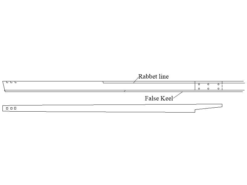
The below may help showing aft section of keel with starboard side view and top view. Note the dashed line as Druxey mentions on the port side of the side view. The drawing you posted brings up a new one for me. I always saw the false keel joint as a single angled mating so it can slide off the one aft each other without damaging the keel should the ship run aground and snag the bottom (false keel) Allan
-
Hitting the like button is not enough. Outstanding workmanship B.E!!!! Allan
- 648 replies
-
- 4
-
-

-
- Indefatigable
- Vanguard Models
- (and 1 more)
-
Shot Garlands
allanyed replied to tmj's topic in Discussion for a Ship's Deck Furniture, Guns, boats and other Fittings
Hi Eberhard I don't know where Goodwin got the design, but I have seen at least one contemporary plan that is similar. See below, the Talavera (74) 1818. I have seen many more that are similar or exactly the same as the 18th century depiction above, that being somewhat flat as you describe. Allan.thumb.jpg.82e4e16f81be604084c06a91937f004d.jpg)
-
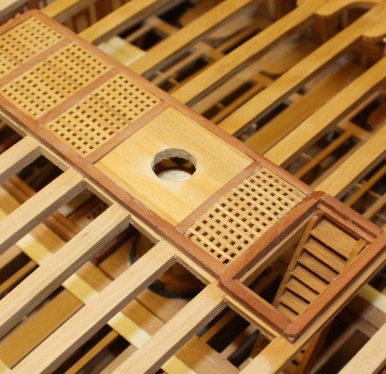
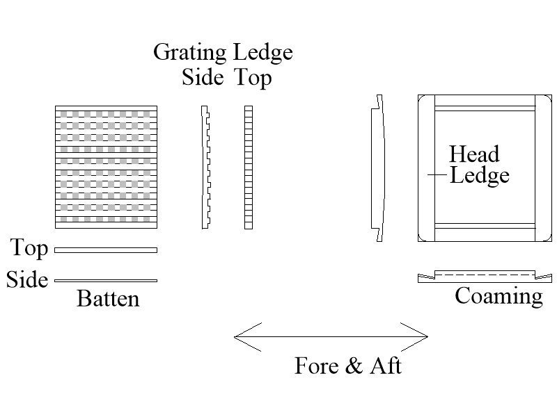
Hard to tell based on the photos, but do you have the battens running fore and aft as they always did with the ledges running athwartships? Allan
-
Shot Garlands
allanyed replied to tmj's topic in Discussion for a Ship's Deck Furniture, Guns, boats and other Fittings
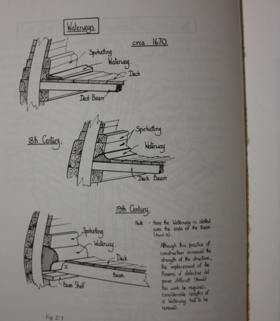
I am sure Roger has a ton more information as the waterway changed in shape and size over time. Examples are below. the latter from Goodwin. Allan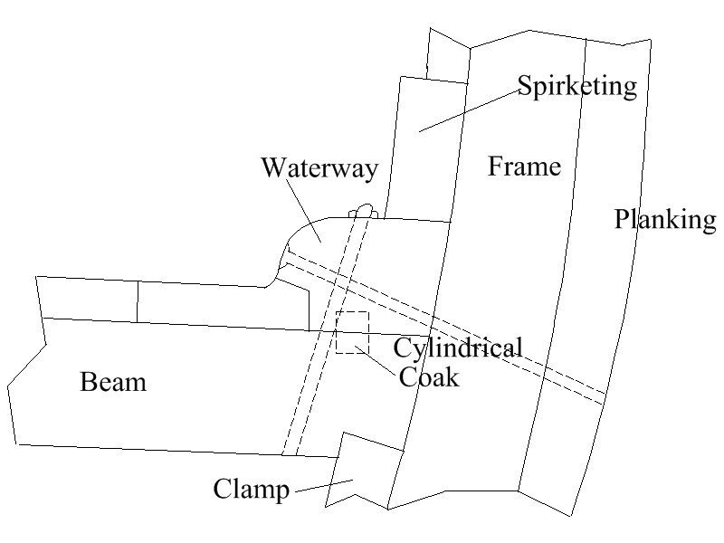
-
Wilkommen to MSW Dieter. You have chosen a great work from a great modeler. Allan
-
Contact Glue
allanyed replied to RolBerg's topic in Building, Framing, Planking and plating a ships hull and deck
NEI Allan -
I realize this is probably a kit problem but why do they supply the wrong cannon pattern? I realize most people seeing your model will never know and it is not an issue for most, just curious if it is a cost issue for them to get it right or something else. Allan
-
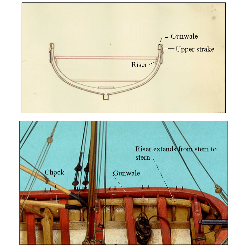
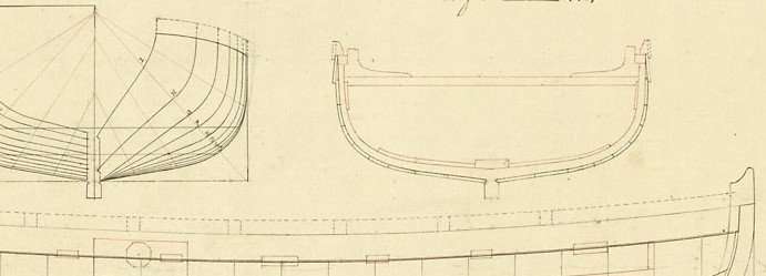
Your model is looking SUPER. There is something that I am wondering about and I have seen it on a couple other builds here at MSW. What is the upper strake inboard above the riser? The gunwale would be about 4" thick and resting on top of the frames and the upper strake (outboard) but there would be no reason for an inboard strake. I cannot find any contemporary cross section plans that show a strake inboard but hopefully a member can post one that shows this if they were used. The pics below may be more clear than my verbal explanation. The upper drawing is from 1799. The model is the Medway ship's boat model from 1742 and the last plan is a launch from 1779 which shows what may be washboards above the gunwale. Allan
-
Welcome to MSW WD140!!! Glad to see you join up. Please take a minute to introduce yourself in the new member forum and tell the members a little about yourself. A moderator may move your post to a more appropriate forum as this one is about how to use the website, not for making requests for plans. There is a forum here called Discussions for Ships plans and Project Research. General research on specific vessels and ship types that might get you some feedback if you post your needs there. Again, welcome aboard Allan
-
It appears she was built as the merchant ship Sting in Bermuda then converted to replace the tender, Pickle about 1800. Unless lines were taken when she was brought to England, there may be no existing plans. I agree with you that it might be better to purchase a set of plans from RMG for similar sizes sloops, especially the Lady Hammond which is also a Bermudan sloop and probably built of cedar as was Pickle. Allan
-
Welcome back to the fray Giovanni. Allan
-
Looking forward to your next idea!! Allan
-
Using the bulkheads in lieu of a full plug is a super idea. Fine looking boat all around! For those without a printer, holly or castello boxwood works well for frames even down to 1:96 (https://modelshipworld.com/topic/35331-31-foot-longboat-1801-by-allanyed-scale-196/#comments post #25 Allan
-
Masking tape for curves .
allanyed replied to LEGION 12's topic in Painting, finishing and weathering products and techniques
Pinstriping tape from automotive stores or the internet works very well. Further to Phil's post #7, if you are painting a stripe that will be bordering on bare wood, spray a clear coat once the tape is on to seal the edges. It will prevent/minimize bleed through when you paint the final color just a Phil explains when using paint to seal the edges. Allan -
Planking Bow
allanyed replied to Loracs's topic in Building, Framing, Planking and plating a ships hull and deck
Welcome to MSW Geoff!!! Planking varied in width but the widest portion along a strake was in the range of 10 inches to 12 inches. Look at some contemporary planking plans to see how they tapered. https://www.rmg.co.uk/collections/objects/search/planking expansion drawing As the taper at the bow was in the realm of half the widest portion midships, using the wider planks makes sense. Once tapered, you still need to shape them as you cannot just glue them in place without having lifting problems. Study the planking tutorial by David Antscherl in the Articles data base here at MSW if you want to learn how to spile planks and if you are going to use strip stock, study the four part video on planking by Chuck Passaro. Allan -
Hi Tom, Please email me the drawing you posted in DXF and DWG format at your convenience and I can see if I can play with it on my program. Just in case also send Worst it as a PNG or JPG and I can go from there. Thanks Allan
-
I would limit the keel to four pieces, maybe five at most. With five pieces they would still be less than 25 feet long each. Allan
-
Lees (or me😀) may have this wrong or it may just be a matter of terminology but on page 80 and page 91 of The Masting and Rigging of British Ships of War he describes the larger lower block of the pair, or larger sheave if a fiddle block, as used for the topsail sheet, not a tack. He makes no mention of there being a tack for the topsails. Allan
-
Hi Bill, What nation and which lines are you referring to for the long tackle blocks (fiddle blocks)? I cannot speak for earlier dates or nations, but according to James Lees on page 68 of The Masting and Rigging of English Ships of War, fiddle blocks were used from 1719 until 1806. On page 166 he describes them being used on yard arms and where ordinary double blocks could foul up. Regarding those on the yard arm, before and after that period two single blocks were stropped together. Hope this helps Allan
-
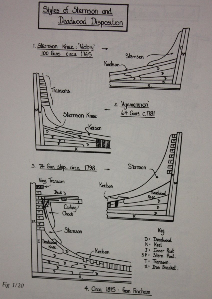
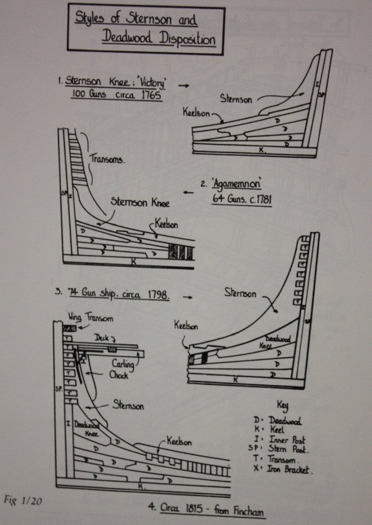
As the keel on Hancock was 115 feet 10" long, I suspect there were no more than five pieces. Looking at contracts of 28 gun and 36 gun, British frigates, the keels were made up of four and five pieces. The 74's called out for no more than 6, but they were about 25 feet longer than Hancock. The deadwood aft looks overly complex. Did you get this pattern from a contemporary source? Several patterns from Goodwin's, The Construction and Fitting of English Ships or War, page 29, ISBN 0-87021-016-5 follows. You can see the various dates that may be appropriate to Hancock even if these are British versus USS. Allan
.jpg.4be374911e38d2abb031c253eab6883e.jpg)