allanyed
-
Posts
8,149 -
Joined
-
Last visited
Content Type
Profiles
Forums
Gallery
Events
Everything posted by allanyed
-
 The copper plates appear to be far more realistic than provided by many kit makers. Nice job of putting them on the hull! Allan
- 261 replies
-
- 6
-

-

-
- Victory Models
- Pegasus
- (and 3 more)
-
I realize this is not seen for the most part on POB, but regarding terminology, internally there are footwales, clamps, quickwork, thick stuff, and lining but nothing called planking.😁 Allan
-
Rigging the Endurance by Occre
allanyed replied to David Enghauser's topic in Masting, rigging and sails
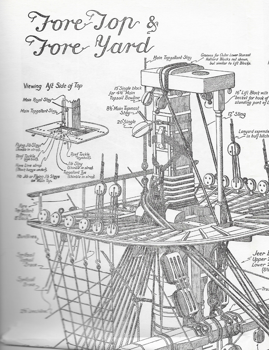
There was an order of dressing of rigging and it made sense once I found it and used it. It varied slightly as new lines came into use such as mizen preventer stays in 1793 or as removed such as truss parrels superseding parrels on the topsail yards in 1806. Pages 158 -159 in James Lees' Masting and Rigging gives all the details. While it is nothing like your ship, the example below of the order of dressing of the lower foremast on the Victory, from a fold out page in Longridge's, Anatomy of Nelson's Ships may be of interest. Allan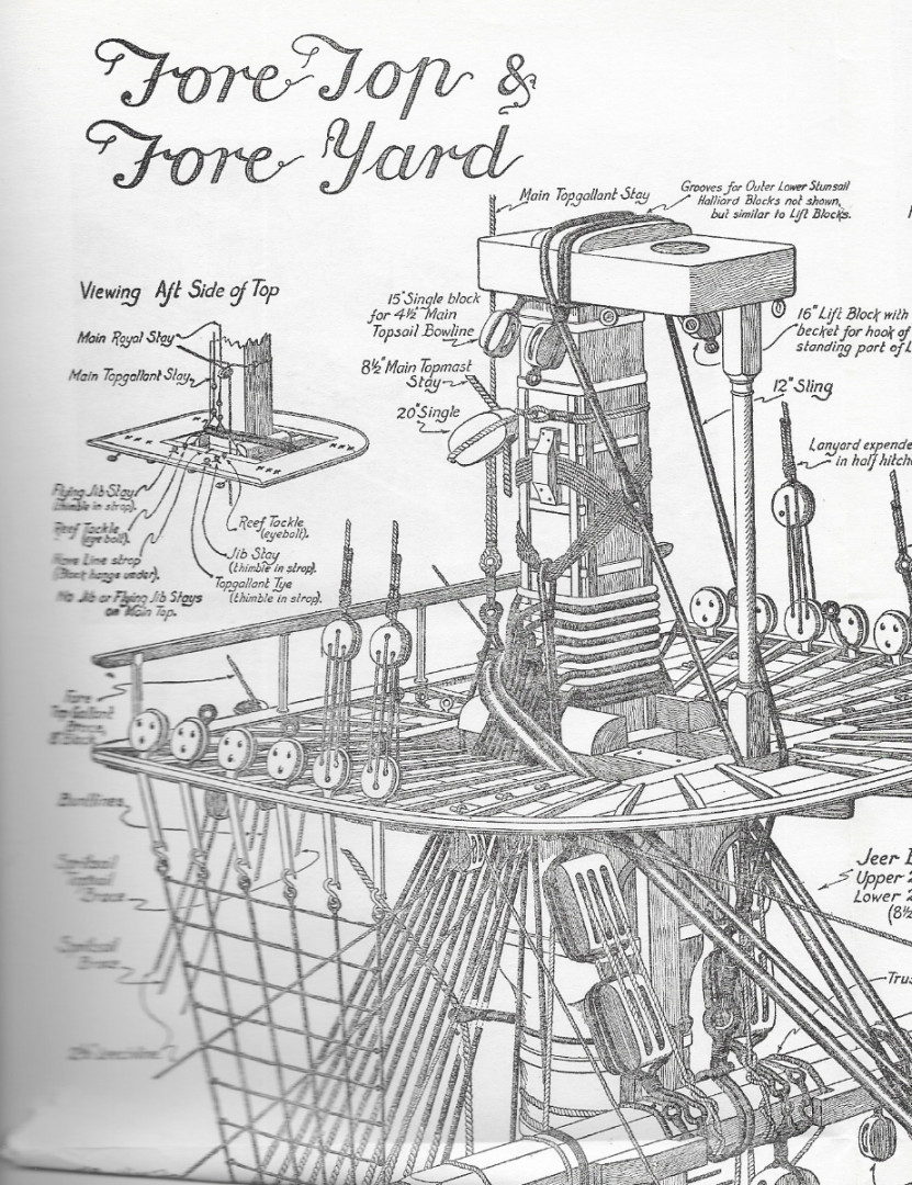
-
I think you are talking about the wales as the fenders ran vertically near midships. If that is the case, the wales were in fact reduced in thickness at the stem on the real ships down to the thickness of the surrounding planks so they could seat in the rabbet at the stem without sticking out and thus being susceptible to catching on something and being ripped off. They were not reduced at the stern, but I can see how this is a problem for you as the "walnut" is notorious for being porous and brittle and not very well suited for ship models compared to other species some other kit makers provide. Allan
-
I get it Chuck and it was fun while it lasted, but why is there still a Non-Ship build forum that has cars and what not? It does not matter to me, but curious why one is OK the others are not. In the end MSW is 44,000 times better than any other ship modeling site!!! Allan
-
I imagine many of the members have already seen the videos and know the story how she was sunk by the British in 1708, but for those who have not, this is an incredible find, worth billions of Euros/dollars in gold, silver, gems and relics. In looking at the video, there looks to be some interesting things regarding Spanish ships of the San Jose era. One that jumped out at me is the cannon. There is no cascabel but rather an ornate loop. Time mark 1:08, 1:46, and 2:20 show these very clearly. Allan https://www.mensjournal.com/news/colombia-holy-grail-of-shipwrecks-20-billion-treasure
- 14 replies
-
- 10
-
-
I like BC for brass as well. For copper I have been using diluted liver of sulfur as I can blacken it after it is in place without worry about scratching the surface during installation. Another plus is that LoS does not stain the wood and a quick rinse/wipe down with a wet paper towel is all that is needed for once it has been applied to the part. Wish it worked on brass as well. Allan
-
Dave, What did you use to blacken the copper? Allan
-
Love it!!! It is great to see you are going a step beyond and not settling. Allan
-
My only experience with 3D printing is for cannon. I emailed drawings to a one man print shop in another part of the US and had 20 perfect barrels for $15, including freight, in a matter of days. I am curious to know what other parts would lend themselves to 3D in addition to barrels and maybe anchors where metal would have been used in reality. I cannot see myself using 3D printed resin for anything that would have been made of wood though. Allan
-
This is very well said. There are few, if any, kits that have the correct gun pattern for a given date/nationality but to have the tooling to cast them in metal in all sizes and scales would cost a fortune. With 3D printing all one needs is a drawing that is accurate in pattern, and size. Details like the cypher are easy to include that are correct for the era and nationality. Another common error is that the lengths are often the stated length, ie: 8 foot, 9 foot, etc, rather than the correct overall length which is longer. I understand the use of plywood for some things including bulkheads, false decks and similar parts but not where the laminations can be seen such as the keel, knee of the head and similar parts. Walnut may be more tradition in kit models even though it is porous, often brittle, and generally looks awful compared to very nice tight grained species that some kit makers such as Vanguard are using. It also may be a matter of cost as well as, or instead of, tradition. Allan
-
Welcome to our motley crew, enjoy your voyage. Allan
-
Warm welcome to MSW, hope you enjoy the voyage!!! Allan
-
VERY happy to see you back here on your Bellona build log. Hope all is well in KW. My better half and I are hopefully taking a drive down or maybe take the jet cat ferry from Marco Island as she has been reading that the town is decorated for the holiday very nicely. Plus, I get to meet with a client and do some research at the Mel Fisher museum so a nice write off.😀 Allan
-
It's not totally accurate but that may not be that important for some. I do wonder if there is a market for yet another Victory kit. Check out the sails, oversize belaying pins and odd looking gratings as they are not realistic but still look nice to many people. The wales are completely wrong but again, it probably does not matter to some builders or any casual observer. Hope we can agree to disagree Keith, but if the pintles and gudgeons are any indication, the fittings may not be very good. They are hugely out of scale. For a first rate around 1800 the pintles would be 5 1/2 inches wide (0.06" at 1:87) Scaling the photos, they look to be closer 0.12" wide, or double what they should be. On the plus side, this kit gives a lot of builders a chance to do a plank on frame model instead of POB. There is always the opportunity to do some research and replace the things that are not correct. Allan
-
Shot Garlands
allanyed replied to tmj's topic in Discussion for a Ship's Deck Furniture, Guns, boats and other Fittings
Got it, thanks Gary. Yep, "anti-idiot" netting for tourists makes sense. Allan -
Think I will stay away from volunteering to do a test run for fear of being chastised or otherwise lambasted for making a suggestion.😁 Allan
-
Shot Garlands
allanyed replied to tmj's topic in Discussion for a Ship's Deck Furniture, Guns, boats and other Fittings
The above what I see in post #29. Did something get deleted or is it only me that is missing something? Without seeing a photo I must say I like the anti-idiot explanation! Allan -
I am not sure it is always a matter of right or wrong as much as common practice. Then again, there is usually a reason things were done certain ways. In the end not all model builders find these kinds of things to matter as much as other builders who find the details to be of varying degrees of importance. As long as we as individuals are enjoying the hobby, that is what counts. Allan
-
Shot Garlands
allanyed replied to tmj's topic in Discussion for a Ship's Deck Furniture, Guns, boats and other Fittings
Thanks Gary, Ergonomically, it makes sense as there is no bending over down to the deck providing a shorter reach and easier on the seaman's back, but I don't think these criteria were a consideration at that time when it came to locating shot garlands. Then again ??? Allan -
I have a project for a new ice cream store and we contracted for a model using popsicle sticks for most of the hull and deck planking. It appears to be birch which is the most common wood for popsicle sticks as far as I can find. In test cutting, shaping and sanding a few pieces it is not bad, so far. Will keep you posted on how it goes here at this topic when I get to the planking stage. The only downside right now is that when the rounded ends are cut off they are the equivalent of 20 feet long at 1:48 so a bit shorter than I would like. Allan
-
Shot Garlands
allanyed replied to tmj's topic in Discussion for a Ship's Deck Furniture, Guns, boats and other Fittings
There is a photo of a build from the late 18th century here at MSW that shows the garlands somehow attached to the bulwarks a small distance above the deck. I do not recall ever seeing seeing this on contemporary models or plans so wonder if this was ever done on a full size ship. It seems to be a lot of work if they had to be bolted to the bulwarks sufficiently to support the weight of multiple pieces of shot rather than having the garland it lie on the deck. If anyone has information on garlands secured above the deck and to the bulwarks, I am interested in seeing how this would have been done. Thanks Allan -
I was in NJ and FL for most of my modeling years, never lived in Ohio. The pear I am talking about was purchased from exotic wood suppliers, and is steamed (Swiss) pear and has a reddish color. Adam, apple is a great wood to work with, especially for carving. I used to live a few miles from an apple orchard and when they pruned each winter they would stack it up to burn it. I would go over before the burn and take whatever I liked with their compliments. It needs to be debarked and the ends painted to prevent checking while it dries for a few years unless you have access to a wood kiln. It can usually be found with the wood suppliers like the box and pear. I understand Cook Woods is a good supplier and I have used Gilmer Woods a number of times. Both are located in Oregon. They do not always have all the species I like to use, but it is a good start for US clients. Allan
-
Sorry to go off track BCDad Roger Wish I knew you came down to Marco. If things change PLEASE PM me as it would nice to break bread and swap sea stories with you or any members that head this way in the winter. Allan
-
Roger Seems like half our neighborhood heads back to Minnesota every May/June for the month of summer. Kidding,,,,, they usually stay until the leaves change in the fall. I may organize them to make a wood raid on your place when they head back next season.😀😁 Allan