


allanyed
-
Posts
8,149 -
Joined
-
Last visited
Content Type
Profiles
Forums
Gallery
Events
Everything posted by allanyed
-
 In order to get rid of the lifting at the bow from edge bending will you be pre-shaping the planks using the method Chuck Passaro demonstrates in the four part video series on your second layer of planking or spiling planks from wider sheets as explained by David Antscherl in the Articles Data base here at MSW? https://thenrg.org/resources/Documents/articles/APrimerOnPlanking.pdf Allan
- 152 replies
-
- 1
-

-
- Flirt
- Vanguard Models
- (and 1 more)
-
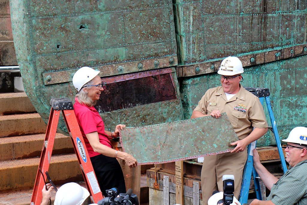
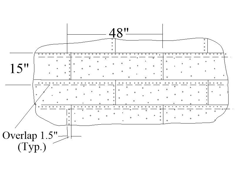
Gary, I am guessing one end wheel could be removed or maybe ground down to eliminate it. Is it adustable? According to Goodwin the plates were sized as shown below so maybe this device is not a good idea for some scales. You may find the photo below useful as well. Allan
-
Great idea if it can be done, but there are so many Victory models and kits. I like that Vanguard comes out with ships that have not been built by the thousands and are of very high quality compared to many of their competitors. Allan
-
Hi Gary, Regarding the overlap, I agree with you. I have seen some plating lately that shows the dimples on one long edge and one short edge so when butted together they have the appearance of an overlap. Much more realistic looking than the riveted plates to be sure. At less than 1:48 it MIGHT be best to leave off any sign of the nails. From what I could find they were 1/4" diameter nails, thus a head of about 1/2" so even at 1:64 the indents would only be about 7 thousandths diameter. Allan
-
Hi Gary, Have you considered just removing all of them and using more realistic copper plates that properly indicate small nail indents on overlapping plates that would be present versus giant rivet heads on plates butted to each other that were never used? In your wonderful research of Victory, did you find drawings, specs, or photos of the plating? It would be interesting to see. Allan
-
Phil, Can you post a picture of the gun pattern(s) he shows with approximate dates (or PM me so we do not hijack this subject😀) Working on a cannon project with others here at MSW and would like to see how the pattern compares to the earliest patterns we have found in detail, that is the Pitt and Brown patterns of about 1600. THANK YOU
-
I agree with Dean. If you are intent on adding sails why not make your own, they are almost guaranteed to be better than the poorly stitched materials found in some kits. The booklet Dean mentions is by David Antscherl at SeaWatch Books for $5. https://seawatchbooks.com/products/swan-iv-sail-making-supplement-from-the-revised-and-expanded-edition-by-david-antscherl Regardless of which kit you choose, research the ship and others like it of that era IF accuracy is a factor for you. In the end get what is most comfortable for you and have fun. That said, by comparison, the one does seem to look more realistic albeit not very accurate in some of the details. Some examples, all of which you can change on your own,,,,, it has belaying pins which the British did not use until about 200 years later, the planking style is fantasy, the pintles are out of scale, and the cannon look a lot more like Spanish guns of that era than British. The book mentioned above is available on Amazon at what seems like a decent price when considering availability and will probably help you with a lot of these kinds of details if you are up for some kit bashing. https://www.amazon.com/Galleon-Great-Ships-Armada-Era/dp/1557503001 Allan
-
First and foremost, welcome to MSW J It would be nice if you would post a little intro in the new member section about yourself. To address your query, according to James Lees in The Masting and Rigging of English Ships of War, page 40, the snaking came into use in the 18th century and he is specific that it was sometimes used during wartime. He does not explain why the lines were snaked together but as it was only rigged during wartime perhaps it was to prevent the stay or preventer stay from coming down if one or the other was parted by shot. He gives a very nice detailed drawing of how the snaking was lashed to each line rather than being knotted to the stays. Allan
-
Assuming you are correct Craig, and I think you are, I cannot believe how stupid of me not to just take the line all the way through to see such a basic thing by myself. Allan
-
Sorry guys it is not the deck. The deck line (top and bottom of the planking) is shown in red on the original draft. I will zoom in further to see if it helps. Will mark the line in question with arrows Druxey, good point. Thanks Allan Line question BBB.PDF
-
The below drawing happens to be the Artois, but it is similar to many others. Is there a name for the line marked below. I have traced it in magenta on the profile plan to see if I could figure it out, but it does not seem to hold any significance. I am sure it has significance as lines were not arbitrarily drawn on these plans so I am curious to know what it is about. The deck line can be seen in red on the original plan so it is not the deck. TIA Allan Line question AAA.PDF
-
This is a great subject..... what size are chain rudder pendants on various size ships? They were to prevent loss of the rudder if it became unshipped and needed to be sized to hold onto the rudder and hardware. I would not rely on Caldercraft having the right size without doing some research. 19 links per inch seems to be almost double the size that could be used. Assume an oak rudder on a 74 gun ship weighs about 7000 pounds. 3/8" chain can hold about 7000 pounds so with two chains, one port, one starboard attached to the spectacle plate, it can hold double that amount. 3/8" chain links are about 2" long. At scale these would be .028" long or about 35 links per inch. I cannot find any specifications so far, so hopefully a member will have sizes from contemporary based sources. (Walther railroad supplies has chain up to 40 per inch.) Allan
-
Head Rails
allanyed replied to DaveBaxt's topic in Building, Framing, Planking and plating a ships hull and deck
It depends on the ship I suppose. Many have them that are above, others between. The location of the bolster needs to be such that the anchor hawsers come into the hull on the appropriate deck at a level that allows installation of the bucklers and their respective support lumber inboard. Allan -
Head Rails
allanyed replied to DaveBaxt's topic in Building, Framing, Planking and plating a ships hull and deck
As to shaping, for me it depends on the thickness and species of wood. I prefer to shape them to match, but if it is thin enough you can soak the piece and then bend it around a jig that is made to match the shape of the hull and hit it with a hot air gun much like edge bending planking. The bolster is probably best carved to shape due to its relative thickness. Regarding the filler piece, what is the purpose? The Bounty model at RMG has no filler piece between the cheeks nor do any contemporary models that I looked at unless the hawse holes are between the upper and lower cheeks as on the pic below. Not to say the plans you have are incorrect, but seem not to be the norm. Allan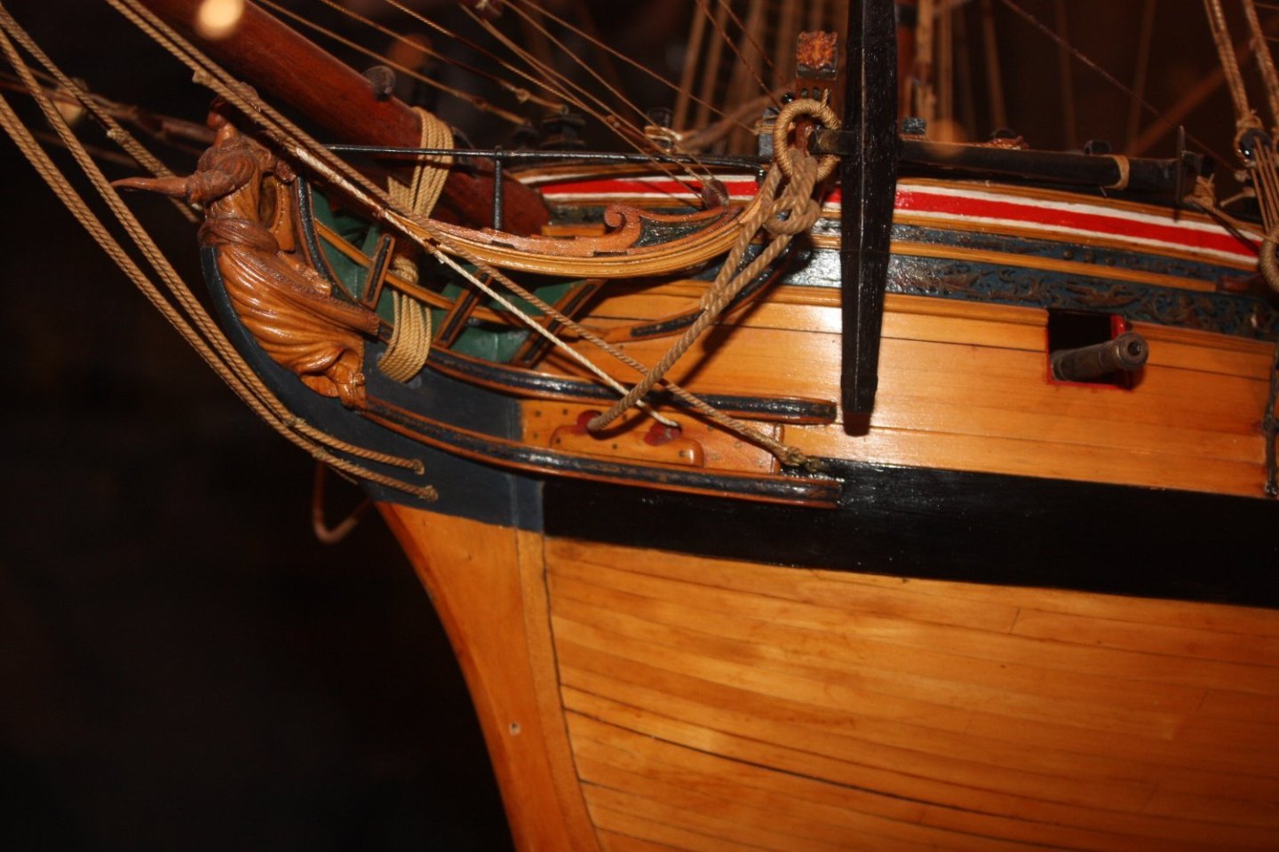
-
Head Rails
allanyed replied to DaveBaxt's topic in Building, Framing, Planking and plating a ships hull and deck
David, Regarding the cheeks, the parts I know of that fay to the cheeks and hull are the wash cant, bolster, and/or trail board. Looking at the contemporary plans of Bounty at RMG I am not sure there is a trail board but it just may not be shown on the plan. As to parts above the cheeks, are you speaking about the main rail and lower rail? If not, sorry to put you into another book that you may not have but there is no easy/short explanation to cover the entire head area. There are about 30 pages going into the details of every piece of the head that took me from a frightened rabbit when it came time to make these parts to a place of comfort after studying them. TFFM Volume II, starting on page 206. It covers main rail, false rail, lower rail, upper cheek, lower cheek, and much much more. Allan -
For the future, ----- it can be done with relative ease using the methods Chuck Passaro presents in the four part video on proper planking techniques, or cutting from a sheet to get the bend rather actually bending a strake. I have done both and it depends on the scale more than anything when deciding which route to take. If I try to bend a piece I make a jig shaped to match the turn at the bow, then soak the pre-sized port and starboard pieces overnight. In the AM I can gently bend each piece around the jig and hit it with a hot air gun until dry. Need to remember they are mirror images as well. Easy peasy (most of the time) Allan
-
Roger are you talking about Tommy Thompson? An old article (2019) can be read at https://www.stuartmagazine.com/stuart-life/people/treasure-hunter-tommy-thompson-in-jail-until-he-admits-where-50-million-of-gold-is/ Allan
-
Welcome aboard. You have made a very wise decision in your choice for a first build, you obviously did your homework. We lose too many novitiates because they have chosen kits that are too advanced or are poorly designed. Allan
-
Have you researched any contemporary plans and models of other 20 gun ships around the time of the Greyhound 1720? I just found some with a quick search on the RMG Collections site, including Tartar (20) 1734 and Biddeford (20) 1727 that you might find appropriate and helpful. Allan
-
Rigging the Endurance by Occre
allanyed replied to David Enghauser's topic in Masting, rigging and sails
Hi Phil, Your rigging work looks extremely neatly done! It may just be the angle of the photo, but It looks like you have the aft shrouds first which would be unusual as the starboard forward-most pair was rigged first, then subsequent port forward pair, and so on moving aft. The stay was then rigged after all the shrouds were rigged. Allan -
Hi D Welcome to MSW!!!! I enjoyed reading your post, especially your desire to do research to get things done accurately. My concern is that this is your first model so it may not be the best choice for a number of reasons for a first time build. Do visit the MSW Articles data base for lessons on such things as proper planking of the hull and a plethora of other useful items. For the hull planking the Antscherl article is tops, but you may also benefit from the four part video on planking by a member here at MSW. https://www.youtube.com/watch?v=KCWooJ1o3cM. Enjoy your voyage here at MSW. Allan
-
The eyes, hooked blocks and stropped blocks are marvels. Great pics, thanks for posting. Allan
- 562 replies
-
- 1
-
-
- vanguard models
- alert
- (and 2 more)
-
Goodwin is one of my favorites in general. His research has saved many of us countless hours of our own research. This layout was a new one for me so a good day of learning 😀. Before seeing this sequence I was relying on that given by Lees but I am not so sure he was including the idiosyncrasies of cutters in The Masting and Rigging of English Ships of War. This brings up a question, for me at least, would cutters fit within the meaning of his title or were they of their category for some things such as rigging? Allan
- 562 replies
-
- 2
-
-
- vanguard models
- alert
- (and 2 more)
-
Your work is astounding. 😀 Question, hope you don't mind. Were the forward shrouds set up like this on the cutters rather than the common sequence, ie: pair on the starboard then pair on the port, etc. with a swifter being the aftmost rigged with an eye splice if an odd number of shrouds? Allan
- 562 replies
-
- 3
-

-
-
- vanguard models
- alert
- (and 2 more)

