allanyed
-
Posts
8,149 -
Joined
-
Last visited
Content Type
Profiles
Forums
Gallery
Events
Everything posted by allanyed
-
 English and European boxwoods (I think both are called buxus sempervirens) are difficult to find and very expensive stuff if you do find some. Castello boxwood (Calycophyllum multiflorum) is great to work with but it is becoming harder to find and prices are up. One source (and I would confirm it is buxus sempervirens) is https://exoticwood.biz/ Allan
 -
Hello from the Scottish North Coast
allanyed replied to Scottish Guy's topic in New member Introductions
Welcome to MSW Michael! Allan -
Kit Model or Plans for HMS Centurion 1732
allanyed replied to Fraser1945's topic in Wood ship model kits
Fraser There is a drawing of Centurion 1732 that was made in 1729 in the RMG Collections which shows the body plan that you can use to draw her frames (or bulkheads if you want to build plank on bulkhead rather than plank on frame.) It also has an inboard profile showing her inner works. It is low resolution but can be purchased in high resolution as a paper plan or digital. It can then be redrawn with CAD so you can use it for laser cutting for some parts. She was built to the 1719 Establishment so there are scantlings of all her parts which can be found in several books, including Scantlings of Royal Navy Ships. The 1719 Establishment can also be found in the appendices in Peter Goodwin's The Construction and Fitting of the English Man of War. There are a number of drawings of additional 60 gun ships built to the 1719 Establishment and 1745 Establishment in the RMG Collections. Allan -
I have some old pieces of limbs from English boxwood that are great for carving but it is not nearly as yellow as in your photo. Those piece are REALLY yellow. If you cut a small piece, is it the same color all the way through? Almost looks dyed😀
-
Chris, I never really thought of that point and it seems like a valid point to be sure. I was more concerned that the end of the strakes needed to be of a thickness that was similar in order to seat properly in the rabbet. What you mention appears to be an additional advantage.🙂 Allan
-
The main wales on Victory are probably about 10" thick based on the Shipbuilder's Repository. The strakes below are down to about 6" thick. The thicker strakes were reduced in thickness to match the thinner strakes so they could fit into the rabbet. Hope this is a little more clear. Pic below may also help as you can see the wales get thicker as you move aft from the stem. Allan
-
I would trust contemporary based information before modern reproductions, even if it is the Victory. I do wonder if this is part of the current 10 year $5million pound project. It is great that they are doing this so she will be around for many more years. I have reached out to Andrew Baines asking about the linings. I HOPE he will respond. Allan
-
THANK YOU!!
-
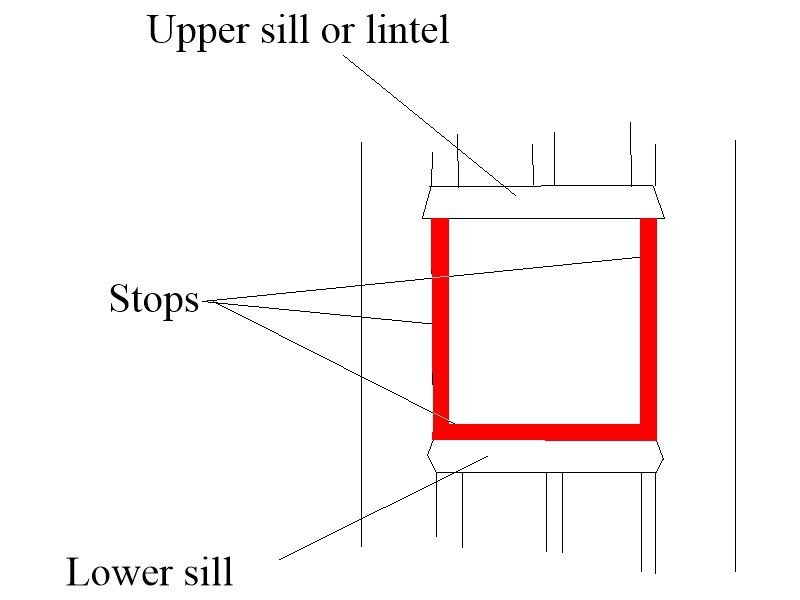
Chris, years ago I thought there was a stop on the top as well, but looking at contemporary models, only one of many that I have seen has a top lining. Personally I would not rely on modern day Victory as a consistently reliable source of information. It is truly a treasure trove of information, but maybe not perfect after all the rebuilds. TFFM goes into the linings in detail and the contemporary models verify this. In the end, doubtless few folks would notice or care. Allan
-
For many of us that is one of the best reasons to choose a model to build!! Good for you!! Allan
-
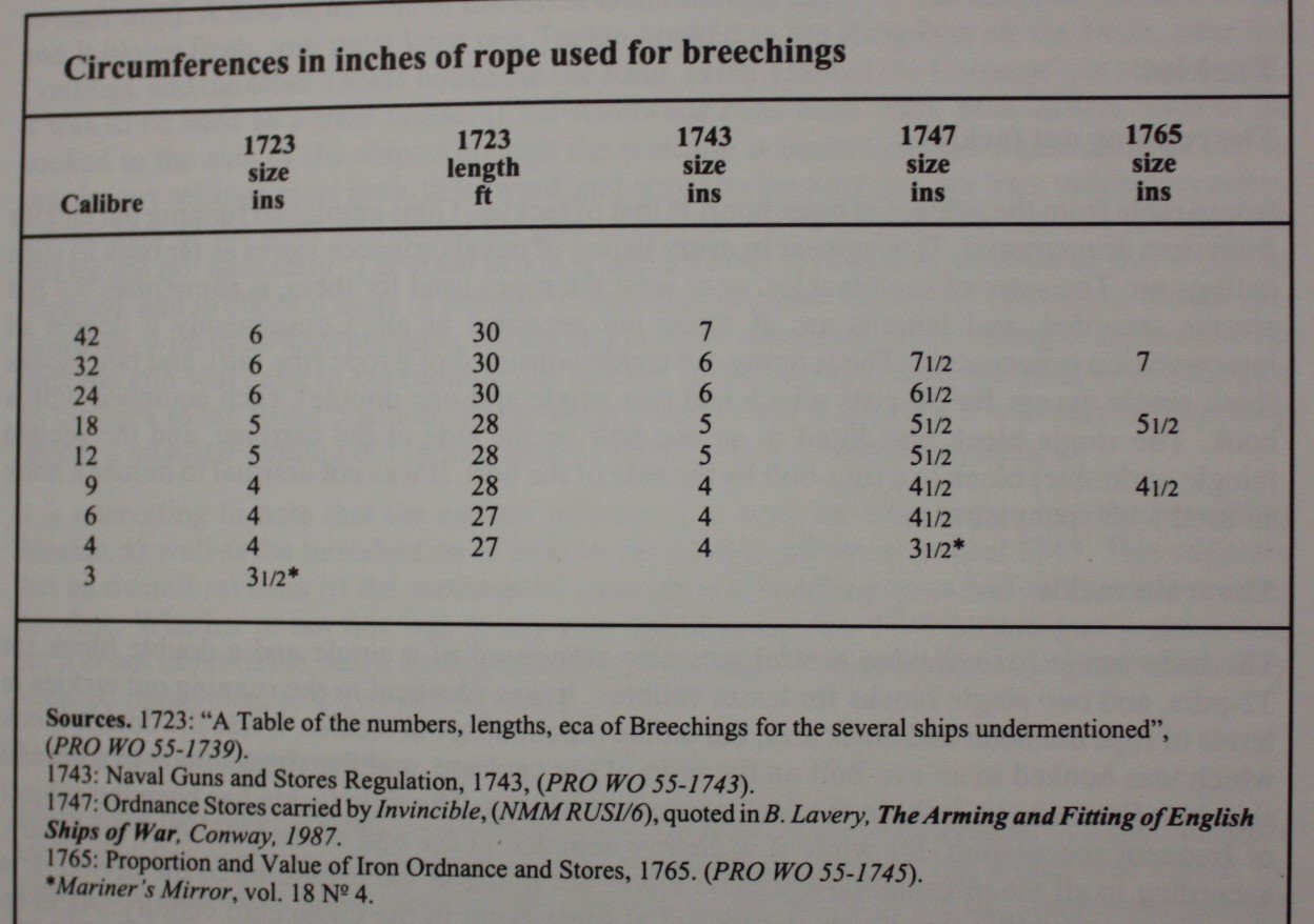
Hi Chris Maybe not too late, and maybe not that important but there were no port lid stops/linings on the top of the ports, only the bottom and sides. The ports were made up with the sills top and bottom and frames on the sides. Linings (only about 1.5" thick) were then nailed to the frames and and bottom sill only. See photos from Preble Hall below. Don't forget that the thickness of the wales at the rabbet at the stem was reduced to the same thickness of the adjacent planking so it would seat properly in the rabbet. It looks like you did that on one wale, but hard to tell from the angle of the photos. Allan

-
Hi Vaddoc, This is intriguing so some questions, I hope you don't mind. What scale(s)? 1mm is the equivalent of 1.9 inches so at 1:48 would be great for the hull planks. What is your sequence? I can visualize holding one plank of a given strake in place and drilling the first hole then screwing into the frame. Then drill and screw subsequent holes in that plank into each frame. That should be about 24 for a 30 foot piece of planking. Next would be remove one screw at a time and insert a treenail. With about 100 frames and 100 strakes of planking you are talking about doing this 10,000 times. I like the idea though and would like to know more about how you perform this. TIA Allan
-
This is indeed an interesting thread. There are several charts of ranging shot from carronades in The History of English Sea Ordnance, Volume 2, including two that show the weight of the charge. The first includes only 68 pounders and the tests had various powder charges from 4 to 6 pounds. The ranges included shots at elevations from point blank to 2 degrees with each size powder charge. I was fascinated that each of the charts show at least the first graze and one shows three graze yardages as well as final distance. There is a note in one chart from the Lefroy Memorandum Book No. 20 in the R.A. Library about the tests taken in 1798 at Woolwich in which their data shows distance only to the first graze. They defined one charge as including the powder at 1/12 the weight of the shot plus the shot and the wad. I suspect the 1/12 the shot weight is what you were looking for. Allan
-
Caruana also gives charge sizes for carronades IF I remember correctly. I'll do some digging and post if it is there. Allan
-
Great stuff Daniel! Can you share the source of these pages? Thank you Allan
-
Period Scale Model Masting and Rigging Tables
allanyed replied to DaveBaxt's topic in Masting, rigging and sails
While the program saves a ton of time and is a great tool for the most part, keep in mind the Danny Vadas program is based on James Lees ratios EXCEPT for the period 1670-1710. It is completely wrong for this time period and really should not be used. The math that Lees uses for his period is extremely accurate but would have been difficult, maybe impossible, for Danny to duplicate in his program. Allan -
Tennfox As she was captured off Sandy Hook by the British, RMG might have some information as the British often took the lines of captures. Perhaps Mystic has some helpful information. Where were you able to find out about the number of lights (windows🙂) on the stern? Could that source lead to more information? Sounds like a fun research and build project!!! Allan
-
Hi Dave, If you referring to the Carronade from Caron and other private foundries I just read a good bit of the chapter in Volume 2 of The History of English Sea Ordnance on these guns and can find no charts discussing the breeching rope sizes. Sorry😕 There are a number of drawings that might be useful though. The problem is that most of the drawings, while contemporary, the caliber is not given so the size of the gun and the bore are unknown. A few do show the bore and the rope but I have no idea how accurate they are. The bore to rope diameter ratio is from about 4.4 to 2 in diameter to 3 to 1. The length appears to be sufficient to allow the slide come inboard such that the muzzle is about a foot inboard of the bulkhead. As to recoil, there were a lot of broken carriages in the early days and the slides were fiddled with, first to make them with less friction (defeating the purpose) and then going back to more friction, but not enough to cause wreckage on the recoil. The carriage itself of course did not move, just the barrel on the slide. There is an interesting section that describes non-recoil carriages which to me is a misnomer as the slides were inclined and the gun and slide rose up and inboard when fired. Wish I had more info for you. Allan
-
What have I done wrong
allanyed replied to Dindsy's topic in Building, Framing, Planking and plating a ships hull and deck
Hi Scott Are you speaking about the line of the hull planking? If so the decks of galleons and even later vessels normally did not follow the lines of the hull. You can see the deck line on the plan below as well as the line of the hull planking via the wales. The inboard profile below is from circa 1695 so a bit later than the San Francisco, but is hopefully a good example. The deck lines are highlighted in red and follow the deck beams which can be seen on the plan while the hull planking is on a different line. For the purposes of the cross section model, any curvature fore and aft midships would be barely noticeable at our scales. Allan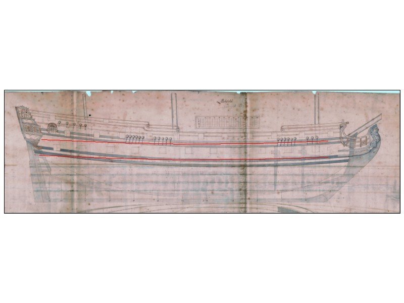
-
Seems they follow a theme in this regard. The other offerings you mention have shown these problems are not without solutions. Allan
-
Dave, I doubt anyone will notice, but as a rule, many builders feel it is better to err by being a little too small rather than too large. 1/2" is about 0.2mm and the human eye can see the difference of about 0.1mm (if next to each other) Diameter/Caliber - I believe the Artois class carried 18 pounders and 9 pounders so the bore diameters would be about 5.25" and 4.25" The chart on the following site might be a little help for diameter of the shot. It shows shot diameter and bore diameter. https://www.arc.id.au/Cannonballs.html Length of the bore - For argument sake maybe go from the touch hole to the muzzle. At 1:64 it will be really close. What I did not find is whether the length of the breech rope is from the bulkhead ring to bulkhead ring or does that include the loop of rope through those two rings and the ends that are seized. There is also the following chart, but I forget where it came from or the era. It might be from Simmons' Vade Mecum which came out in 1812. There is a second chart below that I put together a while back but it only gives barrel lengths at various scales. If you do not have Excel I can send as a PDF. Length chart.xlsx
-
Hi Gregory That was my thought as well but then I looked at drawings in The Galleon by Peter Kirsch. I have no idea if his drawings are correct but he identifies the bitt pins at the fore and main masts as knight heads. It could be because these old ships often had carved knight's heads on top of the bitt pins. I cannot find this term in any other source but would be interested to know if this was a common term for the bitt pins in the days of the galleons. Richard Endsor identifies them in The Master Shipwright's Secrets on the later galleons of the 17th century as bitts,, same as in later years, not knight heads. Maybe the terms were interchangeable at some point. Allan
-
Bill, Are you looking for which lines go through and belay to the various knightheads? There is scant information on belaying points on later ships in the days of sail, so finding information based on contemporary sources for older vessels such as galleons could be difficult. There is some good rigging information in Richard Endsor's books but they are English not Spanish. Lees gives good details, but again it is for English ships and only from 1625 on. Allan
-
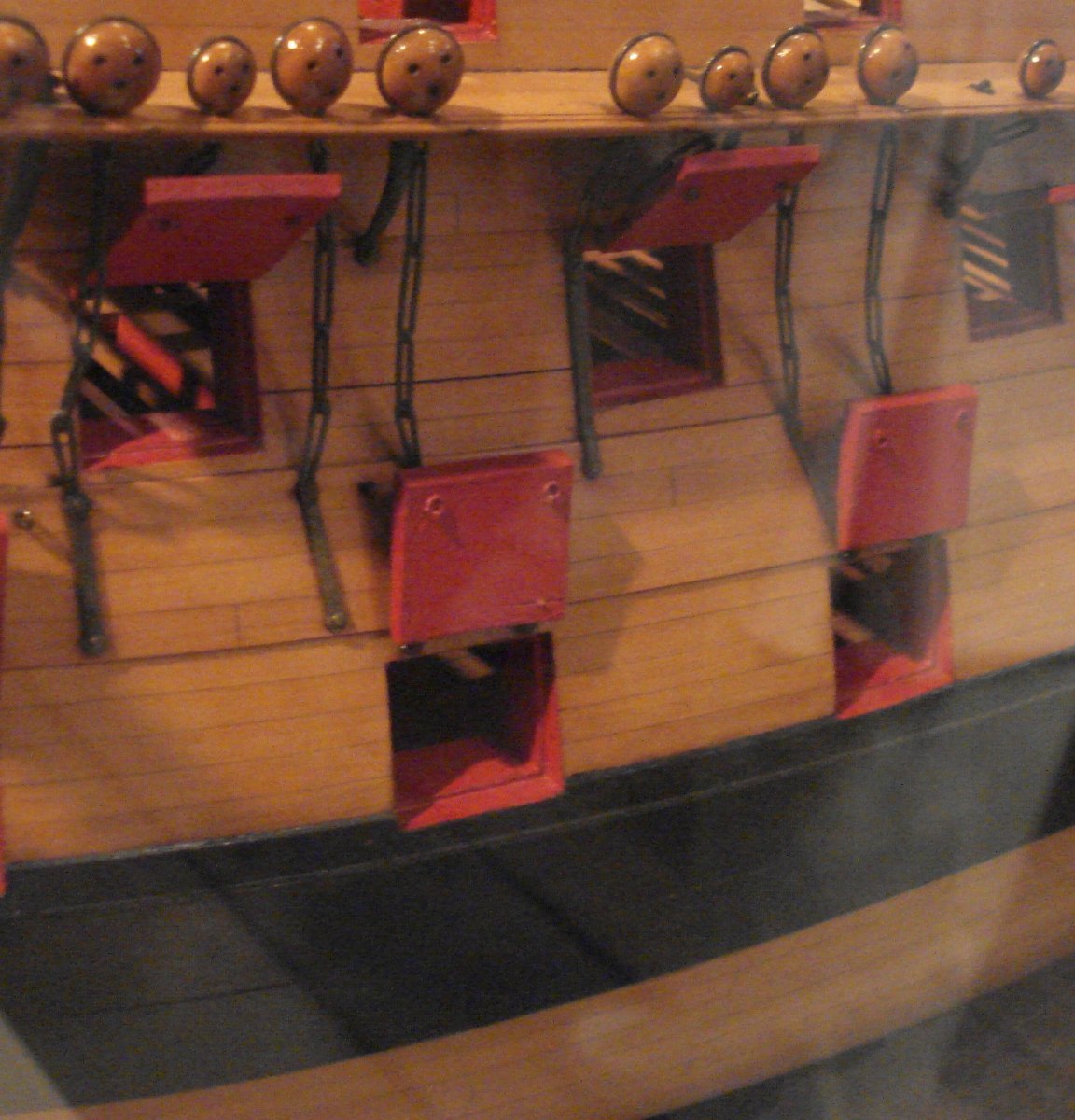
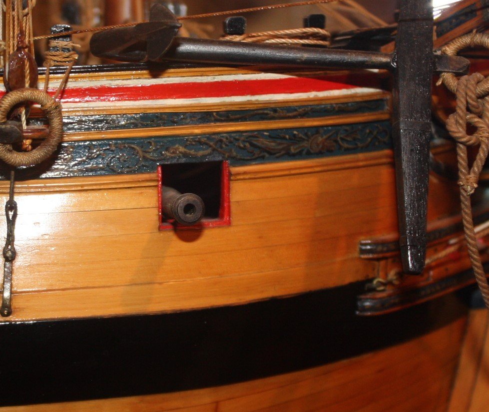
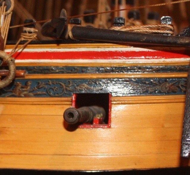
The breech rope is sometimes too short on the models we see. There is scarce information on this but Caruana gives a little. For a 9 foot 18 pounder for example the breech rope was gun was 27 feet long (5 inches at 1:64). This is also consistent with the figure of 3 X length of bore that Dr. Phil wrote in AJohnson's topic above. Interestingly, the breech rope, while made of the best available hemp would stretch as much as 15% after only a short period. The gun tackle was 6 times the length of the bore and from 2" to 3" circumference depending on the caliber. The chart below for breech rope may be helpful. It is from Adrian Caruana's, The History of English Sea Ordnance Volume II page 385 Allan