HOLIDAY DONATION DRIVE - SUPPORT MSW - DO YOUR PART TO KEEP THIS GREAT FORUM GOING! (Only 75 donations so far out of 49,000 members - C'mon guys!)
×


allanyed
-
Posts
8,149 -
Joined
-
Last visited
Content Type
Profiles
Forums
Gallery
Events
Everything posted by allanyed
-
Welcome to MSW Eric. Loved your intro! If your models are as well done as your introduction, you will have great success. Regarding your first build choice
-

Bending hard brass.
allanyed replied to navarcus's topic in Metal Work, Soldering and Metal Fittings
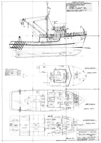
Angel, It looks like your prop is in the wrong place or the diameter is too large. Is it possible to relocate the propellor shaft or go with a smaller diameter prop? Also, you can add a piece similar to the sketch below although it is probably not a good solution. If the ship had a wooden keel then this would work well and could also take a false keel across the entire length of the ship as well. Can you tell us which vessel this is? Thanks Allan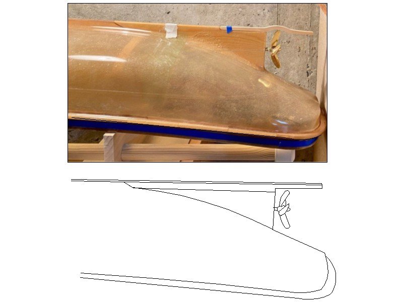
-
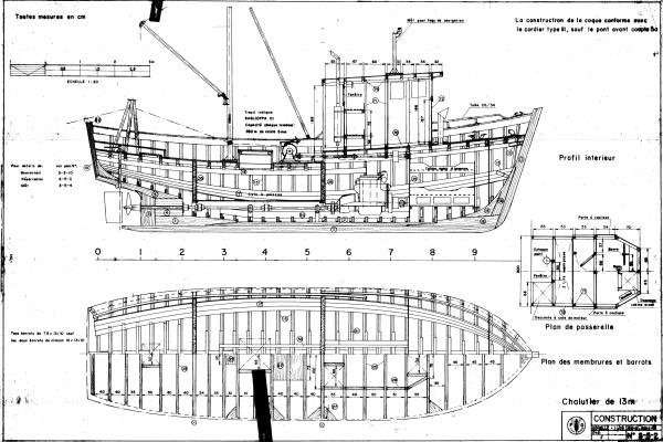
Similarly you can draw a box that is any given dimension in both the x and y axis such as 4 or 5 inches (100 or 150mm) somewhere on the drawing that you want to have printed. Once the drawing is printed, check the length and height of the scale box with a vernier caliper to confirm the printed plan is accurate. For larger drawings I like to use architectural engineering printer shops and ask them to check the scale box on the printed sheet. They have rarely had to make minor adjustments. I have also gone to Fedex offices that have large format printers. More often than not they have had to make small adjustments to get accurate results which they were happy to do. For those that do not do their own drawings but get prints from RMG and other sources, the copies are suspect as the original plans are often distorted to some degree which is not surprising after a few hundred years. Allan
-
Bending hard brass.
allanyed replied to navarcus's topic in Metal Work, Soldering and Metal Fittings
Looking at drawings of various trawlers and boats I still cannot figure out what Navcus is looking for. Attached show skegs that are below the prop so I assume (usually a bad idea) it is this area. If the skeg has to be bent to clear the prop it seems like the prop reaches below the keel which is odd for these boats. Hope he or she posts a drawing as now I am curious.🤔 Allan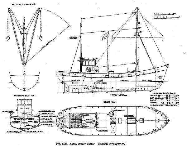
-
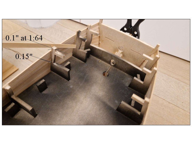
This might help. From the Shipbuilder's Repository 1788 which should be close for Agamemnon 1781: Fourth futtocks moulded at the upper deck 9 3/4" Top timbers <at the top end> moulded in the range of the forecastle 5 1/4" The dimensions below are what they would be if made to scale 1:64 This would apply to the forward frames as well. It looks like the forward most frames moulded dimension is too heavy. Perhaps the kit has it extra thick due to the pressure of the planking bend in that area. Allan
-
Richard, If you are relegated to using brass, cleaning the assembled pieces with a solution of pickling acid is by far the best method in my experience. If there are blobs of solder I will file off any excess first then soak in the acid batch. Sparex #2 is one brand that works well and can be found on line. Vinegar works but not nearly as well as the Sparex in my experience. Once pickled rinse in water and dry then blacken. I find copper easier than brass in many situations. It is easy to solder the pieces together, then clean with a file and/or steel wool followed by Sparex or try acetone. They can then be fixed in place and then blackened with diluted liver of sulfur in situ with a small brush. Rinse with a clean brush with water. The diluted LoS will not stain the surrounding wood. Allan
- 32 replies
-
- 2
-

-
- Victory
- Artesania Latina
- (and 1 more)
-
Doug, Welcome to the best ship model website in existence. Allan
-
Welcome to MSW Mberg Allan
-
Tiziano You are most welcome and thank you again for allowing all of us to travel along with you on your journey. I am emailing you an idea you might like. Allan
-
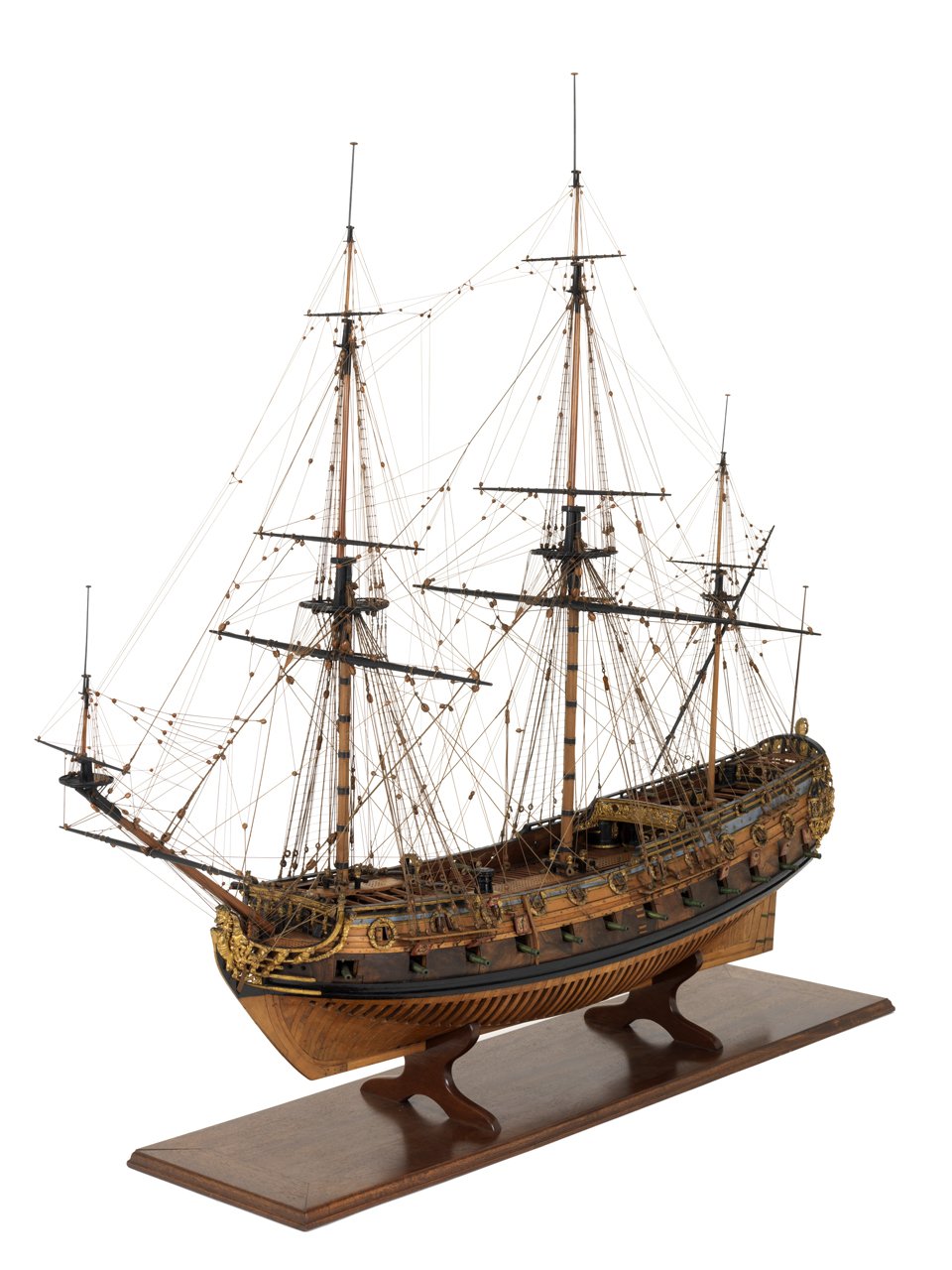
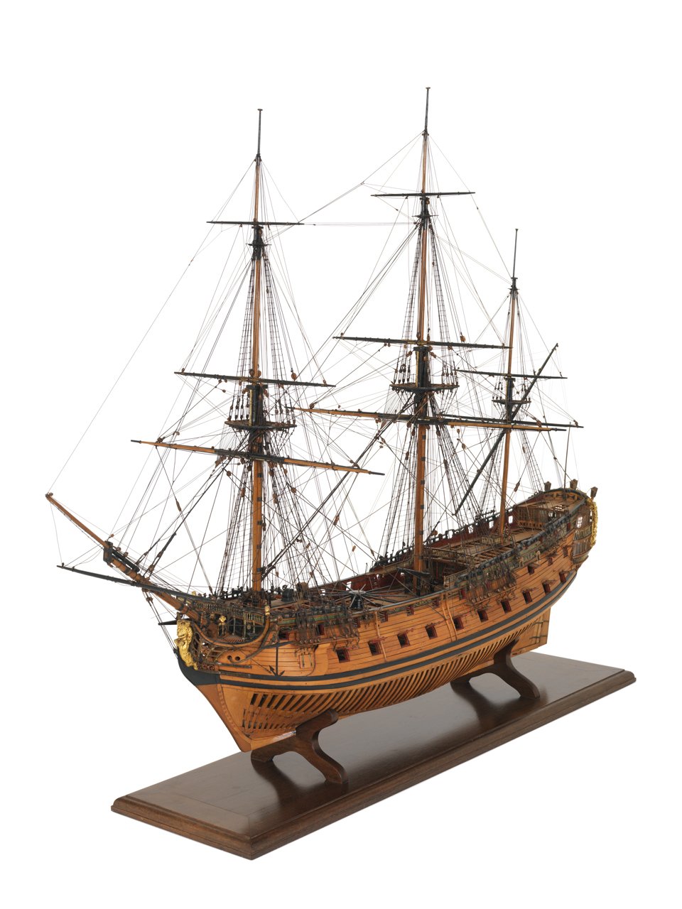
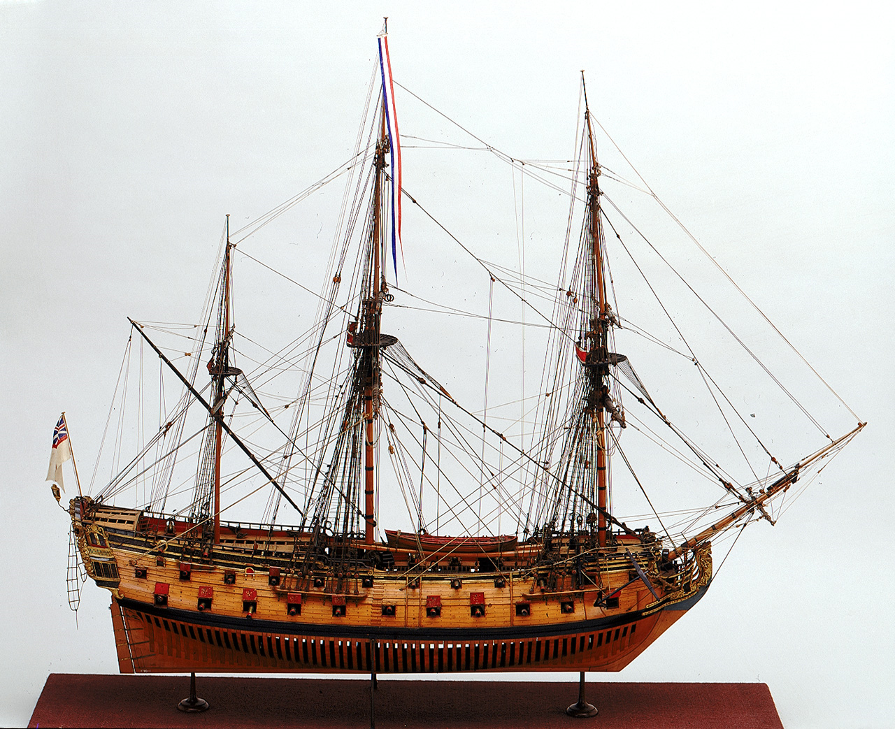
Welcome to MSW John! Not to worry about the sails, you are not alone. While there are contemporary models rigged with sails, there are also many hundreds, including those at the Royal Museum Greenwich and Preble Hall in Annapolis, that are fully rigged sans sails. Three examples from the RMG Collections website of models built in 1695, circa 1714, and 1720 follow. Allan


-
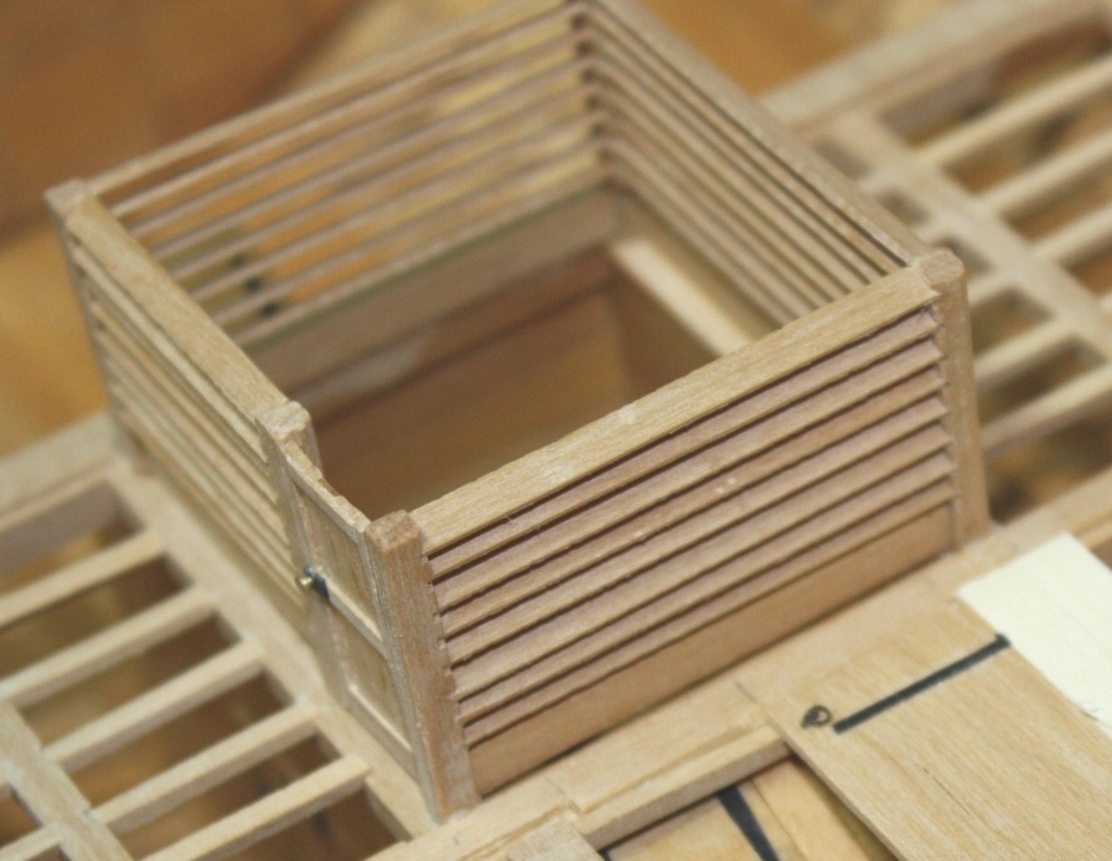
I realize the kit has the supplied parts, but the future and FWIW, the bulkheads over the well on the orlop were typically louvered or partially louvered in the upper portion rather than having completely solid bulkheads. I could not find any reference that the upper well area was made entirely with solid bulkheads on Victory but she (and other ships) may be an exception. Allan
- 32 replies
-
- 2
-
-
- Victory
- Artesania Latina
- (and 1 more)
-
Hi Gregory Yes I am, but as with so many things very few are cast in stone on these ships of old. This is the first document I have seen that specifies other than singles on smaller than 32 pounders so heretofore I had relied on Caruana. The dates are very late in the 18th century so I wonder if this was a time of change for the types of blocks. So many choices. If Caruana missed this one too at least I am in good company. Appreciate your point. 😀 Allan
-
Welcome to MSW Jay. What is your area of interest, kit, scratch, era, etc? Allan
-
Curtiss (easier than p40warhawk1😀) First, WELCOME TO MSW. Please post a little intro in the new member forum and mention your project as it may get additional responses. Fiberglass saturated in resin can be applied but it will be the texture of fiberglass and difficult, if even possible, to give a super smooth finish. The following is not a great way to go for a one off, but will give you an idea of how fiber glass hulls are so nicely finished. When fiberglass is used to make a hull it is done in steps. The following is somewhat simplified but it should give you an idea of what is involved. First is making a plug that matches the shape of the hull (in this case, your model hull). This is finished to super smooth surface than coated with a mold release wax. This waxed hull/plug is then coated with gel coat and left to cure. Once cured a thick fiberglass and resin coat is made, usually with some wood or other reinforcing so the mold will not flex later on. Once the fiberglass resin is cured the plug is removed from the mold. Next the mold is coated with a mold release wax. Gel coat is then applied to the mold and allow to cure. Last, fiberglass and resin is layered in an appropriate thickness and allowed to cure. Once cured, the new glass hull is removed from the mold and the mold is ready for the next hull to be made. For your purposes and to use the hull you have already made as is, some coating such as just gel coat might work or more simply why not fine sand the hull you have, then apply four or five coats of a good quality spray finish/paint? There are wooden models with simple finishes that have been around for over 300 years. I am sure there are members here that can give you the benefit of their own experience for simple yet effective way to get what you are shooting for. Allan
-
Chris is of course correct that TFFM is based initially on building a fully framed model, but the volumes have a lot of application for any ship model in the days of sail. Such things as proper planking in volume I, making various realistic small parts such as a ship's wheel or chain pump housing and much much more in volume II and rigging in Volume IV. In the end no one book will answer address every ship, era or nationality. Allan
-
I have gotten great pleasure in following your build log Tiziano. I truly hope to see you again and the model the next time we are in Italy. Ciao amico mio Allan
-
Hi Gregg, I love the blocks from Syren. Hard to tell from the photos, are you using the internally stropped blocks that would be on Bluenose? They take a little doing to assemble but they enhance the model a lot as the blocks are prominent and very realistic. Regarding the silk span sails, there is a little booklet on making sails by David Antscherl at Sea Watch books for $5 as well as the Tom Laurie video mentioned by wmherbert that shows similar techniques. https://seawatchbooks.com/products/swan-iv-sail-making-supplement-from-the-revised-and-expanded-edition-by-david-antscherl Allan
- 184 replies
-
- 1
-
-
- Bluenose
- Model Shipways
- (and 1 more)
-
Totally agree with you Dean. My library is in the neighborhood of 75 books, but there are fewer than ten that get used on a continual basis. Basics include Lees for rigging, Lavery and Goodwin for details, TFFM for a lot of "how to" information, and Scantlings of the Royal Navy for dimensional information on virtually every part of every size ship in the RN from 1719-into the early 19th century. Schooners bring out Chapelle. The Articles Database here at MSW has a ton of information as well. Allan
-
Drill bit suggestions
allanyed replied to SiriusVoyager's topic in Modeling tools and Workshop Equipment
My go to is McMaster Carr https://www.mcmaster.com/products/drill-bits/drill-bits-1~/ Allan -
Definitely worth a try Phil, but need to be careful to avoid------------->

-
HI Richard, I hope the following sketch might help. The upper well stanchions were tenoned into the top of the orlop beams and the bottom of the beams in the deck above. The orlop and platform planks were often short pieces that sat in recesses along the upper edges of the orlop beam. I am not sure if this was the case in Victory circa 1805, hopefully some member will have more information. Allan

- 32 replies
-
- 3
-
-
- Victory
- Artesania Latina
- (and 1 more)
-
Daniel, Not only is your workmanship grand, the photography is exceptional as well. Allan
- 562 replies
-
- 5
-
-

-
- vanguard models
- alert
- (and 2 more)
-
I was going to ask if this was doable and practicable so thanks for pointing this out. My Byrnes plate has seen hundreds of passes and I wondered if it and the moulding cutters you posted can be similarly sharpened? Heretofore I have made my own moulding cutters from stiff back razors or pieces of hack saw blade but for the price, these cutters look like a great alternative. Allan
-
Fantastic. Very few kits address this feature resulting in a lot of bowlegged figure heads. Chuck hit a grand slam home run with this kit. Allan
-
David, Looks like it was a case of necessity being the mother of invention, Very well thought out and relatively simple. Allan