


allanyed
-
Posts
8,149 -
Joined
-
Last visited
Content Type
Profiles
Forums
Gallery
Events
Everything posted by allanyed
-

Laser cannon bracket
allanyed replied to mediocremodeler's topic in CAD and 3D Modelling/Drafting Plans with Software
Nice work, it looks close to the below, a common single block. How did you round the edges? A block/rock tumbler is a huge time saver and does a great job if you are doing this by hand. Allan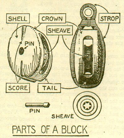
-
I agree, burnt umber is a better choice. Allan
-
I have used black tissue on deck planking with good success. For other joints such as scarfs an alternative that I have found to work very nicely is to add a drop of black acrylic paint to a puddle of PVA glue, mix and apply. These joints have held up for many years so I am confident the little bit of paint has not weakened the joint. Allan
-
Miniature Russian carving tools
allanyed replied to druxey's topic in Modeling tools and Workshop Equipment
I usually agree with you Eberhard, but on this one, not so much. 😀 The smallest U chisels would be a challenge for 99.5% of anyone trying make these. These are exquisite chisels that would take someone with lots of experience and time to make a set as well made as Mihail's. Maybe some member could take up the challenge which would be fantastic.😁 Allan -
There are several brands, Avery being the best, but maybe not worth double the price or more than others. $13.60 for 100 sheets for Betckey brand https://www.amazon.com/s?k=Label+Paper+8.5X11&crid=3BVCA6WSG59V1&sprefix=label+paper+8.5x11%2Caps%2C106&ref=nb_sb_noss_1 Allan
-
Thanks for sharing this Phil. Great model and great photos!!! I did a quick search and $75 seems to be spot on. Includes shipping with Amazon Prime so I may take the plunge. https://www.amazon.com/Speedlite-Adapter-Pentax-Olympus-Cameras/dp/B09685NGWJ Allan
-
This is a great way to go. An alternative that I switched to some years ago is to print on full size sheets of label paper. Cut out the drawing of the part somewhere near the lines, peel off the backing and stick on the wood. Once the wood part is cut and sanded to the lines I find it easier to remove the paper and clean up compared to rubber cement or other glues. I do try to print as many parts as possible on a standard 8.5"X11" page to save on paper. Allan
-
I contacted Model Expo and asked what kind of wood this is. Caveat emptor I wrote: Is this boxwood buxus sempervirens (English boxwood) or calycophyllum multiflorum (Castello)? If not, can you please let me know what species it is? Thank you kindly for your help. Their reply is below: Message It is yellow in color. Other than that, I do not know.
-
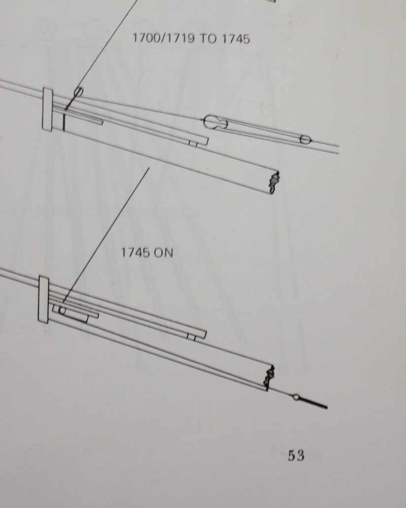
Good question Alan and there may be no conclusive answer. The set up appears to be a workable substitution for using a fiddle block. Based on Lees The Masting and Rigging of English Ships of War), Page 54 from about 1680 until bees were introduced on the sprit, fiddle blocks were used on the fore topmast stay with the stay tackle fall. Lees goes on to write on page 56 that the main top mast stay also had a fiddle block and the stay tackle fall. Then again, ships often had their own rendition in accomplishing a given task. By about 1745, the stay ran through sheaves under the bees sheaves to a heart of thimble. There are detailed drawings of the set up of the fore topmast stays on page 53. (see below) Allan
-
P-51D Mustang by CDW - FINISHED - Dragon - 1:32 Scale
allanyed replied to CDW's topic in Non-ship/categorised builds
Your build brings back fond memories of Daryl Greenamyer flying his P51D at Tonopah and then his F104 for the low altitude speed record over Mud Lake. Also enjoyed the scene at the end the movie Top Gun-Maverick with Tom Cruise flying his P51. Had the great fortune to meet and interview Daryl as I had worked for PPG at the time and we had supplied to paint for the F104 from the Ditzler division of PPG. Allan -
Looks like you are off to a good start with a great subject. Speed is not really a part of ship modeling, so you should have no worries about going slow. Allan
-
The cat has me scared being so close to the model, (which looks really great.) Love the planking and seeing belaying pins that are to scale. Kudos to both Vanguard and you. Looking at various cannon barrel patterns from the 18th century I cannot find barrels that look like these. Do you know what pattern these are? Thanks! Allan
-
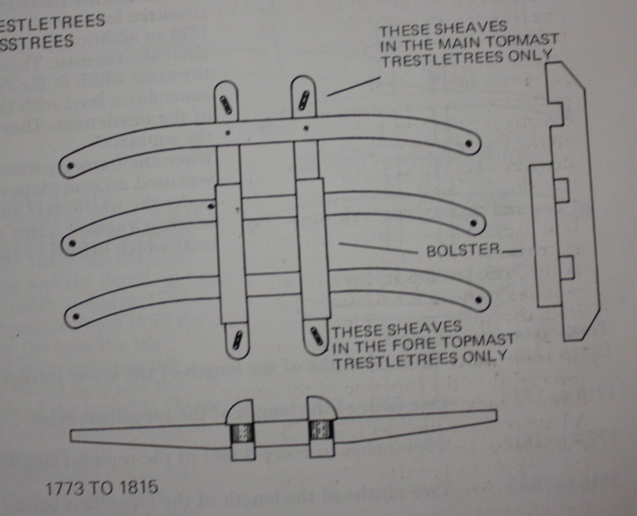
Thanks Glenn, I think there were bolsters on the topmast trestletrees, at least according to Lees (below pic). Not really that noticeable on the model though. Allan
-
Hi Glenn, Is the last photo the top of the topmast or topgallant mast? Thanks Allan
-
Period Scale Model Masting and Rigging Tables
allanyed replied to DaveBaxt's topic in Masting, rigging and sails
In Danny's quest to make the Lees ratios available to everyone for free and easy to use it appears he may have some ratios wrong. In addition to the 1670-1710 period which is not useable, he may have misinterpreted the ratios in other time periods for the foremast diameters, therefore his diameters for the foremast are wrong so it may be best not to use his system for the foremasts diameters. Lees states that the diameter of the foremast is the same proportion as the main mast. I believe this means proportion to the foremast length, not the main mast length. If not, why not just writer the diameter of the foremast is the same as the main mast, which it was not. For example, for the Artois class, 1794. Main Mast Length Diameter Lees 92.645' 27.79" Vadas 92.645' 28.236" Foremast Length Diameter Lees 83.38' 25" Vadas 83.38' 28.236" For possible confirmation that the foremasts were smaller in both length and diameter, at least for the approximate period in question, I looked at some contemporary plans of masts. The foremasts are smaller in diameter than the main masts. An example are plans J7801 and J 7796 at RMG and on the Wiki Commons site in high resolution. for a 74 gun ship . The main mast maximum diameter is 37" and length is 111.6' The foremast maximum diameter is 32" and has a length of 95' 8" From David Steel's The Elements and Practice of Rigging 1794 The diameters in proportion to the length, in the royal navy, are as follow: viz. The main and foremasts of ships of 100 to 64 guns inclusive, are one inch in diameter at the partners to every yard in length. Ships of 50 to 32 guns inclusive, 9/10 of an inch to every yard in length. And ships of 28 guns and under, 7/8 a of an inch to every yard in the length. https://maritime.org/doc/steel/ Allan -
It appears the kit is not without its challenges already but will you be marking out the lines of planking so you can accurately taper the hull strakes of planking? Then again, if Protector had a coppered bottom most of the planking below the wales will be covered. Allan
-
Kit Model or Plans for HMS Centurion 1732
allanyed replied to Fraser1945's topic in Wood ship model kits
There are all the deck plans for a 60 but it is a 1745 Establishment plan rather than 1719. ZAZ1907 at RMG Still it may be useful if coupled with the 1719 Establishment scantlings. It actually shows carlings and ledges, lodging and hanging knees as well as the beams which are not commonly shown. https://www.rmg.co.uk/collections/objects/rmgc-object-81698 Allan -
My fault Druxey. Just went with what I saw on line which I know is not always the best idea. 😕 From the American Bee Journal As beeswax is the primary construction material of the beehive, its chemical composition is integral to how the hive functions. This same material, the storage location of food resources and developing brood, must be relatively non-reactive, so beeswax's neutral pH (7) suits the need perfectly.Aug 1, 2015 Allan
-
Hi Ken IF you do decide to change them, it would probably be easier to unrig the lines and open the upper holes then re-rig rather than removing the blocks and reinstalling. Allan
- 59 replies
-
- 2
-

-
- Alert
- Vanguard Models
- (and 1 more)
-
The material of your rigging line will be part of the equation. In general a wax with neutral pH is best. As paraffin is alkaline (pH of 9) it could affect the longevity of the fibers. How much depends on the type of rope you are using. Bees wax is typically pH neutral so may be a better way to go if you want to use wax. In either case, wax will hold dust and very difficult to clean so be sure your model is properly cased. There has been mention of conservator's wax, hopefully some members can shed more light. Allan
-
Period Scale Model Masting and Rigging Tables
allanyed replied to DaveBaxt's topic in Masting, rigging and sails
That is my take as well. Proportions of the foremast are the same proportions as the main mast. For example if the diameter of the main mast is one inch for every three feet of length of the main mast the diameter of the foremast is one inch for every three feet of length of the foremast. FWIW regarding accuracy the human eye can only perceive a dimension difference of about 0.1mm if the objects are within the same field of view. Allan -
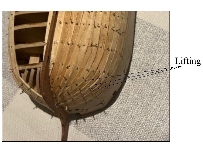
For the first planking layer it is very forgiving as you can sand and fill. For the second layer, it it is not to be covered with a copper bottom you may want to study the four part video on proper planking by Chuck Passaro. https://www.youtube.com/watch?v=KCWooJ1o3cM Nearly all your planks appear to be lifted. Even with a more severe taper as Chris discusses, you can still get lift if the planks are not properly formed for the bend and so they all end at the rabbet rather than coming to a point and short of the rabbet at the stem. If the planks are preformed there is no need for nails. Finger pressure for 30-45 seconds if using PVA glue or a few seconds with CA is all that is needed. Allan
- 146 replies
-
- 3
-
-
- Adder
- Vanguard Models
- (and 1 more)
-
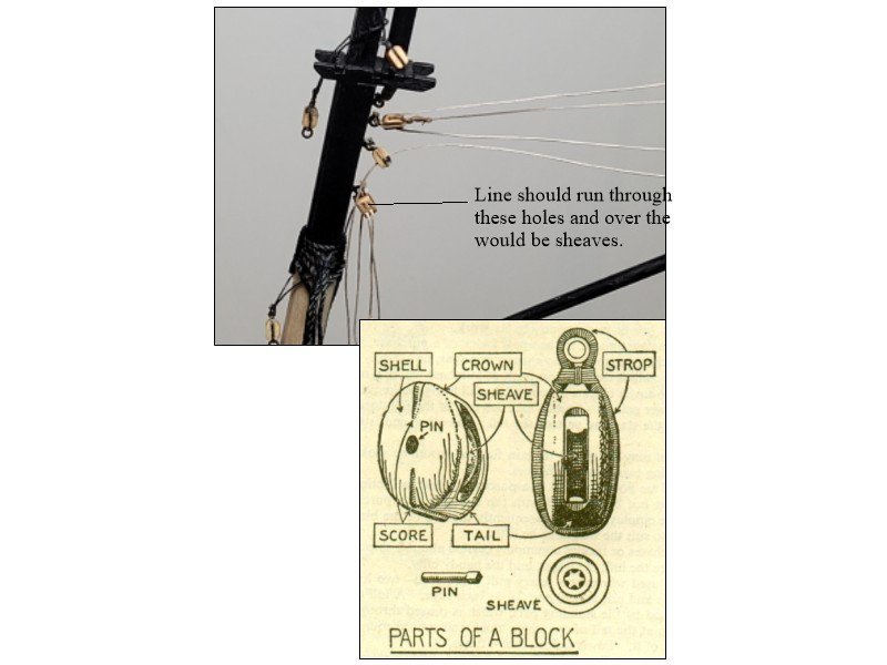
Nice neat work! One small thing, some blocks look to be upside down so the lines are running under the sheave and over the tail rather than over the sheave and under the crown. Sketch may be more clear than words. You can see that on a real block there is no room for the line to run under the sheave. For our purposes and scales these openings are usually just another hole drilled as the line covers it as it runs down but still the line should be in the upper holes. Allan
- 59 replies
-
- 3
-
-
- Alert
- Vanguard Models
- (and 1 more)
-
I agree with Rusty. Don't fight it Glenn. Based on the many build logs here at MSW and elsewhere, for a full size vessel Chuck's is the gold medal winner. Allan

