allanyed
-
Posts
8,149 -
Joined
-
Last visited
Content Type
Profiles
Forums
Gallery
Events
Everything posted by allanyed
-
 Giampiero I would love to see your model in person one day. I hope to see Tiziano's model of Euryalus the next time we are in Florence and it would be a thrill to see your model of Pegasus if you are not too far from Naples as we will there in 2025. BEAUTIFUL WORK!! Allan
 -
Blocks: wood, card or 3D resin?
allanyed replied to georgeband's topic in Masting, rigging and sails
There is an excellent explanation of a common/easy method of making wooden blocks with hand tools as well as their proportional dimensions in The Fully Framed Model Volume IV pp. 61-63. For tiny blocks (1.5mm and smaller) McCaffery goes into some detail in his book Ships in Miniature on making punches for making paper blocks. Allan -
The bulkhead spacing on many kits has a much bigger spacing of the bulkheads (deck beams). In the case of Polaris from OcCre, as mentioned above there is no such ship in real life so maybe it's best to go with what feels right to you as it is a beginner kit. See post #5 in the topic https://modelshipworld.com/topic/34238-occre-polaris-is-there-a-real-role-model/ For example if this was a multi deck ship the upper deck beams are about 4 feet asunder. The forecastle and quarter deck beams are closer to 2 feet asunder. For your single deck vessel it is probably a guess, but two feet to three feet asunder would probably be OK. Give careful consideration to the hull planking which is usually much more of a challenge. Study the tutorial by David Antscherl here at MSW in the Articles Database and the four part You Tube video by Chuck Passaro as it will serve you well in the future. Allan
-
You wrote. How much more difficult is it to cut and lay individual deck planks vs full length strips? In my own experience, it is not. In practice many times I found it easier to do typical scaled 25 foot lengths. There may be a problem though as your build is POB and the spacing of bulkheads may not be conducive to realistic butt shifts. If that is the case, full length strakes may be better and then just fake the butts. Allan
-
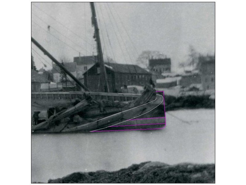
While the below probably will be of little to no help for building the model itself, you may find it interesting as a fan of ECB. Allan https://mysticseaport.org/explore/vessels/emma-c-berry-noank-smack/
-
I could find no clear answer, just more questions. Most of the photos of boats on ships that I looked at had nothing stowed but there are a few that had some things on board. There is a photo of a cutter and larger boat on a ship on page 217 of The Arming and Fitting of English Ships of War by Brian Lavery. There is nothing in the cutter, including the rudder. The other boat, which looks like a launch or longboat boat, has rope and oars stowed. The oars rest on the thwarts but pass under some kind of cross piece. I thought this might be the windlass, but looking at contemporary drawings such as the long boat and launch below, the windlass is too low for the oars to rest on top of the thwarts yet pass under the windlass. Another example is https://www.rmg.co.uk/collections/objects/rmgc-object-66300 but both of these may be the model builder's choice, not actual practice. Also, ships of war might have a different set of rules on such things. Having any loose items left in the boats while on board was probably a bad idea. With multiple boats, and before having multiple davits, often some would be stacked one on the other, another reason to not keep items stowed on board. Seeing a few items on board may or may not be how it was done but, for me, having a few of these items add to the overall look to a boat build. Allan
-
Welcome to MSW Doug! From the photos the model looks lovely. Maybe some closeups would be better if you are looking for input on anything specific. Allan
- 9 replies
-
- 2
-

-
- Syren
- Model Shipways
- (and 1 more)
-
This was emailed to the SW Florida ship modeler membership and I found it interesting. Hopefully others here will, as well. Allan
- 1 reply
-
- 4
-
-
Baker, Fascinating article, thanks for posting. Allan
-
Like Phil, I would use Lees' formulas but keep in mind they are for English ships from 1625 to 1860 so there may be other info out there that is more appropriate. For our scales, the Lees figures are probably very close. I THINK my math is right on this. If you are unsure of the topmast shroud size, but know the lower mast diameters, again from Lees, you can multiply the diameter of the appropriate lower mast X 0.198 for the fore and main masts to get the circumference of the top mast shrouds and futtock shrouds. The circumference of the mizzen futtock shrouds would be 0.25 the diameter of the mizzen lower mast. At our scales finding the exact right size rope is difficult unless you make your own, but hopefully this might give you a little guidance. Allan
-
Gary, Late to the game, but glad to be here and see your build. The cheeks on your fore and main masts extend down about two-thirds between the hounds and deck which is great to see. These are sometimes found too short on models of ships built after 1773. Thanks for sharing your work. Allan
-
Actually, Druxey spotted it, I just enlarged it to see what it was all about. Good eye for the old guys.
-
Hi Phil Black tea has a slightly low pH so probably not harmful to the wood. Reading up on its use on wood, I found the following: Tea can be a safe and natural way to clean wood floors. Black tea contains tannins, which can enhance the wood's color and depth, and add a light, warm "stain" that brings out the wood's natural warm tones. The tannins also naturally clean, enhance, and protect wood Sounds like it might be a good idea but I have no experience with using tea. Hopefully some other member has some experience with using tea they can share or you can be our pioneer and give it a try😀 Allan
-
Extremely well done! Looking at the gratings they look "grate" The battens run fore and aft and there do not appear to be any open holes next to the head ledges or coamings which is often missed in some builds. Are these supplied with the kit or are they aftermarket or scratch made? Kudos! Allan
-
Scott Have you followed Ed Tosti's build log on the clipper Young America here at MSW? https://modelshipworld.com/topic/10678-young-america-1853-by-edt-finished-196-pob-extreme-clipper/#comment-322547 If you are interested in that build Ed drew all the plans and authored a three volume set of books available from Seawatch Books. https://seawatchbooks.com/collections/edward-j-tosti Allan
-
Masts and Bowsprit - Glue or Not?
allanyed replied to Coyote_6's topic in Masting, rigging and sails
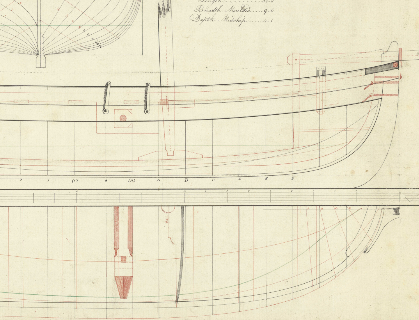
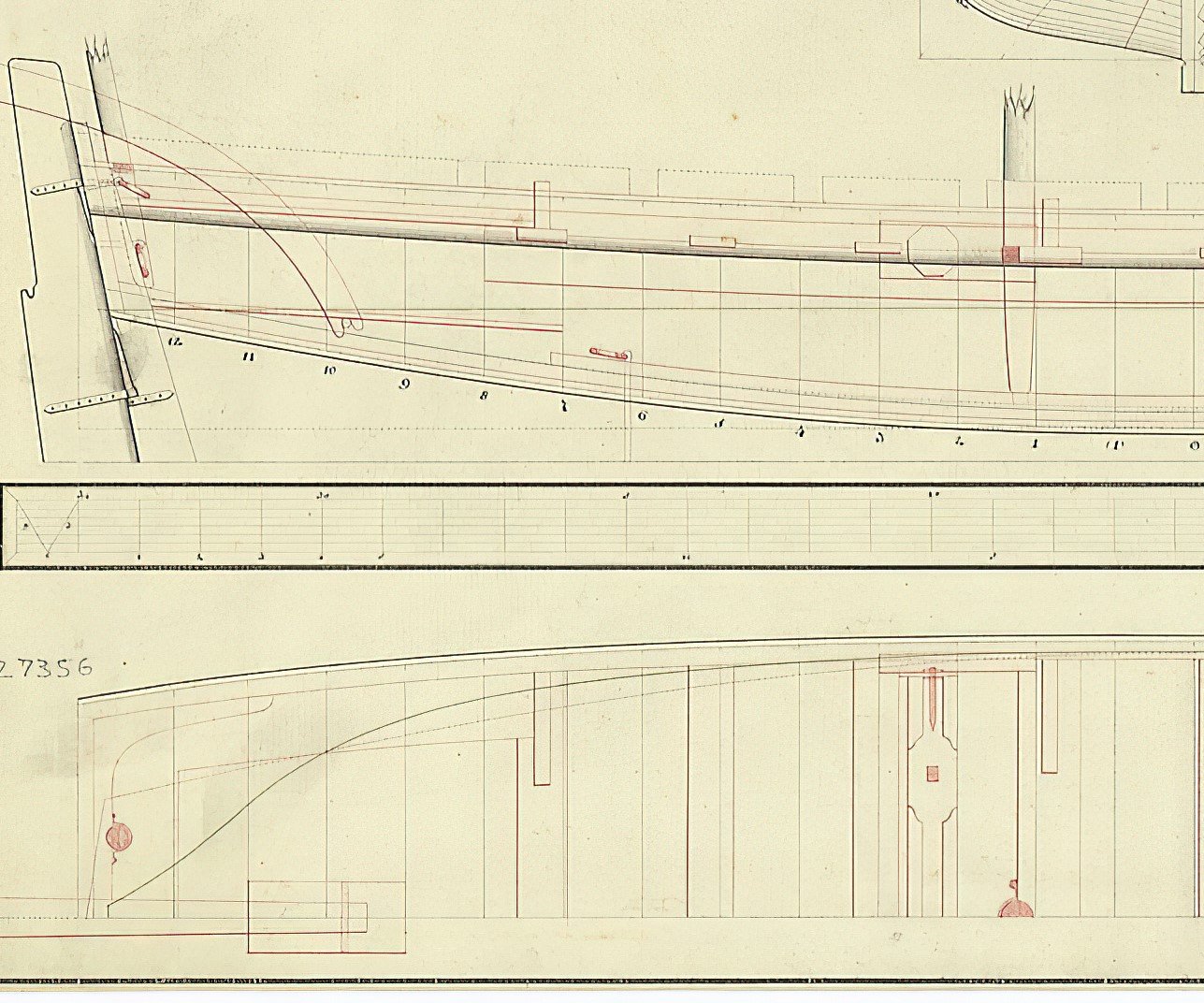
I thought contemporary drawings of masts may help, including the shape of the foot or heel but of the ten high res plans that I have found, to my surprise none of them show the heel itself as the drawings stop at what appears to be where top of the step would be. Lees does not address the heel of the fore, main, or mizzen mast that I can find in The Masting and Rigging English Ships of War. Hopefully some member can shed more light on this. Peter Goodwin does give some detail on the steps in The Construction and Fitting of English Man of War as follows: In general the step for each mast consisted of a large baulk of timber, usually oak, fashioned in such a manner that it straddled the keelson. A mortice was cut vertically into the upper surface in which the tenon of the heel of the mast sat....... The mortice and tenon were always made to the following dimension: The tenon at the heel of the mast was half the diameter of the mast in the fore and aft plane, and had a width two thirds of the diameter of the mast athwartships. The depth of the of the tenon was usually about half the diameter of the mast. I suspect this is generally good information but would be very surprised if were not variations in the dimensions. Allan -
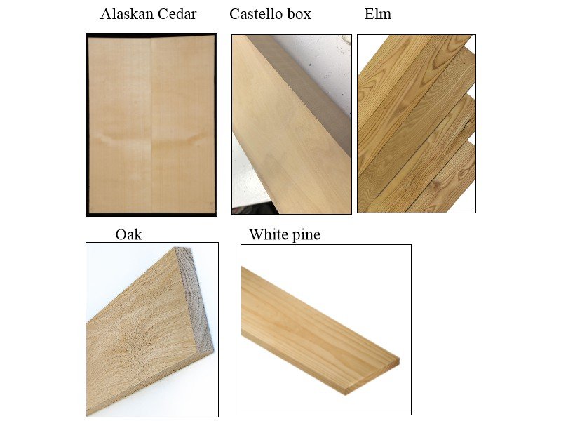
I believe the most common species for keels were oak and elm as pine was relatively weak for large vessels. Regardless you may find all of these are much too grainy for your model. The below shows these species compared to a couple other choices commonly used on model ships, Alaskan cedar and Castello boxwood. English/European box is great but costly. Basswood and poplar is less grainy but you might find them too soft for a keel. Allan
-
Masts and Bowsprit - Glue or Not?
allanyed replied to Coyote_6's topic in Masting, rigging and sails
If the foot of the mast is properly shaped to being square and rests in a square hole in the step it will not rotate and the rigging will hold it down. If the mast is round at the foot and can twist while rigging is applied it would probably be better being glued in place. Allan -
You mention European built vessels so there would be differences with those built by Spain in Havana and the Philippines. I have no idea how accurate the following article might be, but it may be a little help. https://www.worldhistory.org/Spanish_Galleon/ Allan
-
This may be a little bit on the edge of the rope coiling topic which has been very informative. Now I know where the beer logo came from or more likely the other way around and the rope coils are named for the beer logo. If there is indeed really some connection with the Ballantine name for what looks similar to Borromean rings the connection with the rope coiling name may be related. Ballantine opened their brewery in 1840 but the logo came about nearly 40 years later. Legend has it that Peter Ballantine saw three wet rings from bottles on a table that overlapped and came up with the logo from that. Allan

-
Hi Harry, Have you looked at the Young America 1853 build log here at MSW and/or Ed's book and plans on her? Maybe it will be applicable to Flying Cloud. If you have not already seen it go to post #131 in https://modelshipworld.com/topic/10678-young-america-1853-by-edt-finished-196-pob-extreme-clipper/#comment-322547 It continues for a number of posts on planking the various decks. Allan
-
Love the Pave Hawk model! WELCOME ABOARD! Allan
-
Rick, Wonderfully executed planking and detailing. I bet your rigging would be a delight to watch as well, but as it is has been a treat to follow. Allan
-
From surfing the net it appear that styrene softens at 212F or a bit higher. Styrofoam is about the same so does not sound like it would work based on this information. A wooden plug made of poplar, pine or balsa that would be removed after the hull is formed may be best. I look forward to seeing the final answer to this one. Allan