
HOLIDAY DONATION DRIVE - SUPPORT MSW - DO YOUR PART TO KEEP THIS GREAT FORUM GOING! (Only 13 donations so far - C'mon guys!)
×
DocRob
-
Posts
1,257 -
Joined
-
Last visited
Content Type
Profiles
Forums
Gallery
Events
Everything posted by DocRob
-
 There is not a lot, I have done lately. I like the creative phase of airbrushing and preparing a certain finish, but it comes with unavoidable drying times, which is time consuming. The Neuspotter got red dots, but wait ugly dots, why? Well, the solution to the riddle are the red crosses, which were masked then, using Kabuki tape cut quickly on my Infiny cutting mat. It´s a rescue drone. Next wase the base coloring, sprayed in Tamiya XF khaki. The other parts got different metal shades all from the Extreme metallic range. The exhausts were sprayed with dark exhaust color, the spindly arms with titanium, the drum like anti-grav unit in duraluminum and finally the lower body in gun metal. Cheers Rob
 -
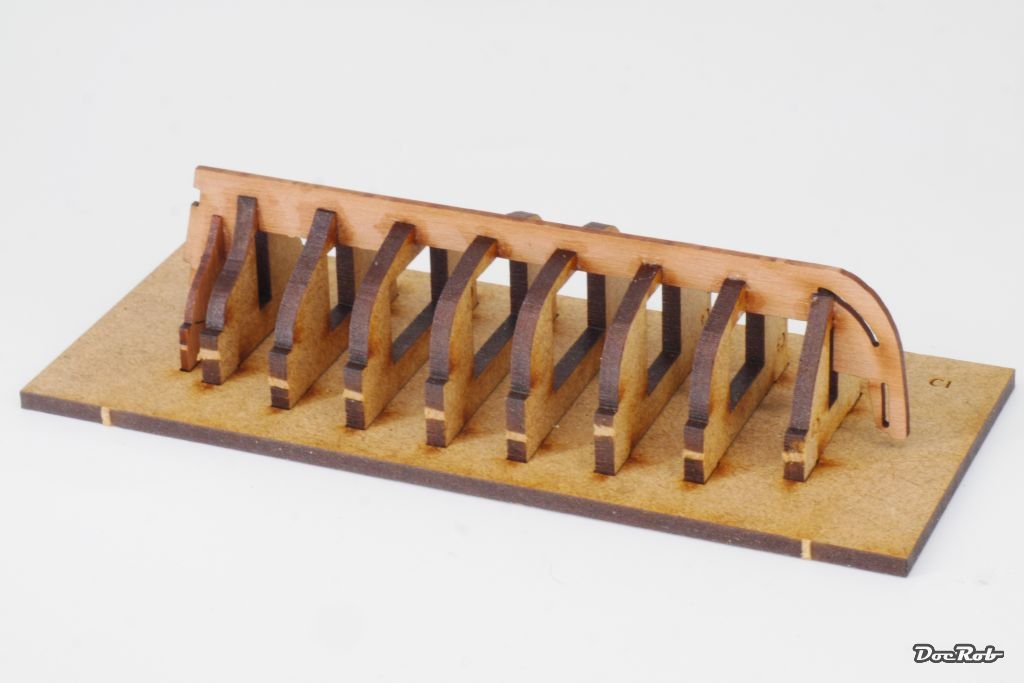
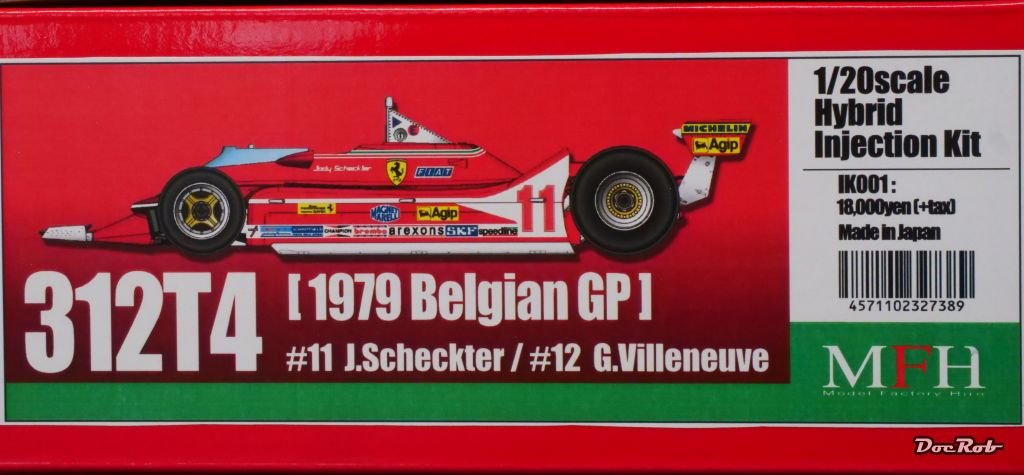
I did realize that, my Cobra Coupe as well as the Ferrari 250 TRI are long gone now. The Williams FW16, I bought was ordered on the firs day of the pre order timeframe luckily. The kit never made it to the normal selling page. Yesterday I received this beauty, which was up as a re-release on the MFH page for one day last month and I missed it. Luckily SpotModel had one left. Cheers Rob
-
My base will be "framed" by a plastic tub, which I sprayed in sand color. For the hovering drone, I added a threaded rod, epoxied onto the base and a nut also epoxied into the lower part of the Neuspotter. I hope, I can cover the rod with some dried grass later. I used it, because it allows to adjust the height of the drone over the surface as well as the angle, because the nut is not glued in in a right angle. The bowl was then filled with plaster of paris. Meanwhile, I primed the parts of the Neuspotter in black and white, black for the pure metal parts, like arms and exhausts and white for the rest. Cheers Rob
-
Congratulations Craig, what a beauty. I hope we will see a future build log about this beauty. I ordered another 1/12 MFH kit yesterday and also received one in 1/20. Lets say, I´m hooked . Cheers Rob
-
The huge Neuspotter drone is nearly finished. Not shown on the pic are the antigrav unit and the exhaust nozzles, which will be added after painting. If I use the Neuspotter in my dio, I have to find a way to let it hover. I guess, I will use slide fit brass tubes for that, epoxied to the base and the drone. Cheers Rob
-
Let me introduce you to this sinister looking drone. The Neuspotter is also based on a design Kow Yokoyama for the MaschinenKrieger universe. The kit was first issued by Nitto 40 years ago and my Wave boxing marks the 40th anniversary. Still it looks cooler and somehow more frightening than modern drones. I started with the sensor unit, which besides the strange colored plastic features coil springs, vinyl tube and different wire diameters for the numerous antennas. The age of the mouldings is visible, but everything fits as it should. I will quick build the Neuspotter and then decide, if I add him in my scenery. To get a better idea about how the Neuspotter looks, I add this illustration, which comes with the kit. Cheers Rob
-
Thank you Alan, I like to build up this kind of weathering in thin layers, which leads to a more real look with depth. Now I have to think about the base and setting. Cheers Rob
-
Well, if that´s your definition of the state the poor pilot is inn, OC . Cheers Rob
-
After evaluating different methods on clear spare parts, I decided to use Tamiya Extra Thin for my sand blasted windows. I used the supplied brush nearly dry and applied the cement very carefully. This is only preliminary, to check the effect and more effects will be added, especially for the front window. Cheers Rob
-
Thank you OC, dusting and some sand residues are for granted. I may try to go a bit further, possibly trying matte clear or even CA glue or thinner for fogging. Cheers Rob
-
On went the second layer of dry paint dabbed on. This time it was a light bone color, called Moonray Flesh. I also applied the paint with a stiff old brush, but this time not only in the direction of the sandblast, but also a bit more from above to simulate some bleaching. This is only the basic weathering and more will be added later with sand deposits and dust everywhere. I have to decide, how to weather the clear parts. I´m open to any suggestions. The sandblast should have been blinded this canopy side, but the other and front window should be relatively clear. Cheers Rob
-
Time for some pointillism. I lied a bit about the looming panic, because the hairspray didn´t work like it should. I hate to alter my original plan, but this time, I didn´t bin the project and instead worked on a plan to add the sandblast effect with different kind of paints, dabbed dryly onto the surface with an old brush. It took a while to get the Extreme Metal Steel dotted, like intended, one side blasted, the other nearly unharmed. Cheers Rob
-
Wow, looks so cool in yellow and the use of enamels is very interesting, especially, as there are no decals involved, which would have called for a clear coat. Cheers Rob
-
Just stumbled into your build log Chris and your Fly looks absolutely fantastic. I love the bright colors and the lots of eye catching details, like cannon rigging, etc. Cheers Rob
- 69 replies
-
- 5
-

-
- fly
- victory models
- (and 2 more)
-
It´s time for some heavy wear and tear for the Kampfanzug. Unfortunately, the hairspray wasn´t working like planned, possibly due to many layers of paint and varnish on top. Right, plan B, scratching, chiseling, grinding, sanding and rubbing was incorporated using a variety of tools, to achieve different looking wear, a messy affair. I don´t like the effect right now, as it doesn´t look like my planned sandblast treatment, but it will have to do as a first stage for weathering. I will try to accomplish the sandblast effect with sponge chipping and stiff brush dabbing. You can clearly see, that one side is almost stripped of paint, while the other is relatively unharmed. I want to simulate a one sided sandblast, to add some dynamic into the weathering. Cheers Rob
-
Thank you for believing in my abilities , but first trails have proved not too promising, I couldn´t activate the hairspray through the layers, as it should have been. I will start the sandblast effect with sanding, scratching and whatever it take, followed by an unplanned sponge chipping, which will hopefully do the trick. Cheers Rob
-
Me too, Ken . I hope, I can realize the look, I had envisioned in my head since the beginning. Cheers Rob
-
Painting and decaling the Kampfanzug is relatively time consuming, as every layer of paint or varnish has to dry properly. I sprayed some yellow areas on the weapon arm and weapons and brush painted many details. A coat of Pledge went onto the camouflage as a gloss base for decaling. The supplied decals were good to work with, luckily. I had different experiences with Hasegawa´s MaK decals, which were rigid and won´t settle on curved surfaces. On top, I put a matte coat, using the matte varnish from Winsor and Newton Galeria, for the first time. I need some more experience with the stuf, but like the result. I used Pledge and the water based matte varnish to hopefully be able to activate the hairspray under these numerous layers. Next will be heavy weathering, the most important step of this project. I hope, I can achieve the desired look. Cheers Rob
- 51 replies
-
- 10
-
-
Ferrari 250 GTO by CDW - Model Factory Hiro - 1:12 Scale
DocRob replied to CDW's topic in Non-ship/categorised builds
Nice find with the manual, at least with the third try, which worked. I had issues with ebay worldwide, when they somehow `lost´ some parts for my 1/1 Jeep, which were not available in Europe at the time. I ordered this one yesterday, but it´s not very thorough I guess, but will be sufficient for my GTO in 1/24. Reference / walkaround book: Ferrari 250 GTO (ref. KOM-FG036) Cheers Rob -
Fantastic work on the interior and engine, Dave. I like your faux woodwork a lot. HGW belts are easier to assemble, when the PE is still on the fret, while you wiggle the belt parts through. The engine looks fantastic and I second your experience with lead wire, it´s fantastic for the job. Cheers Rob
-
On my island, it is impossible to get any spray cans imported since years. It´s not due to poisonous ingredients, it´s because they changed the type of plane, which transports them and some rules apply to the newer ones. I use Mr. Surfacer from the jar since then. It sprays absolutely fantastic, thinned with Mr. Leveling Thinner. I have grey, black and white with the grade from 1000 to 1500. Tamiya rattle can primer was more convenient, but I adapted. Cheers Rob
-
On to the camo. It´s the FU-52 disruptive desert scheme, I planned for the Kampfanzug. Not that such a thing exists, I made it up, because I wanted to achieve something different, but desert related. The idea is to build a camo from 3 mm wide Kabuki strips added with some 10 mm squares. The angles should be from about 75 to 90 percent, not less. I tried to get an even uneven pattern as a result. The masking took some hours obviously and I made sure to, there is no chance of color bleeding, rubbing all strips in and using a toothpick for the corners. Funky isn´t it? Now on with the paint, in this case Tamiya XF desert yellow. I sprayed it a bit less diluted than usual, to hinder bleeding under the masks. Masks were removed only minutes after application. I prefer to get rid of the masks fast, when the color isn´t completely cured, but dry to the touch. The camo has a kind of razzle dazzle look to it, but this will fade with weathering and all the abuse, I will put onto it. Cheers Rob
- 51 replies
-
- 11
-
-
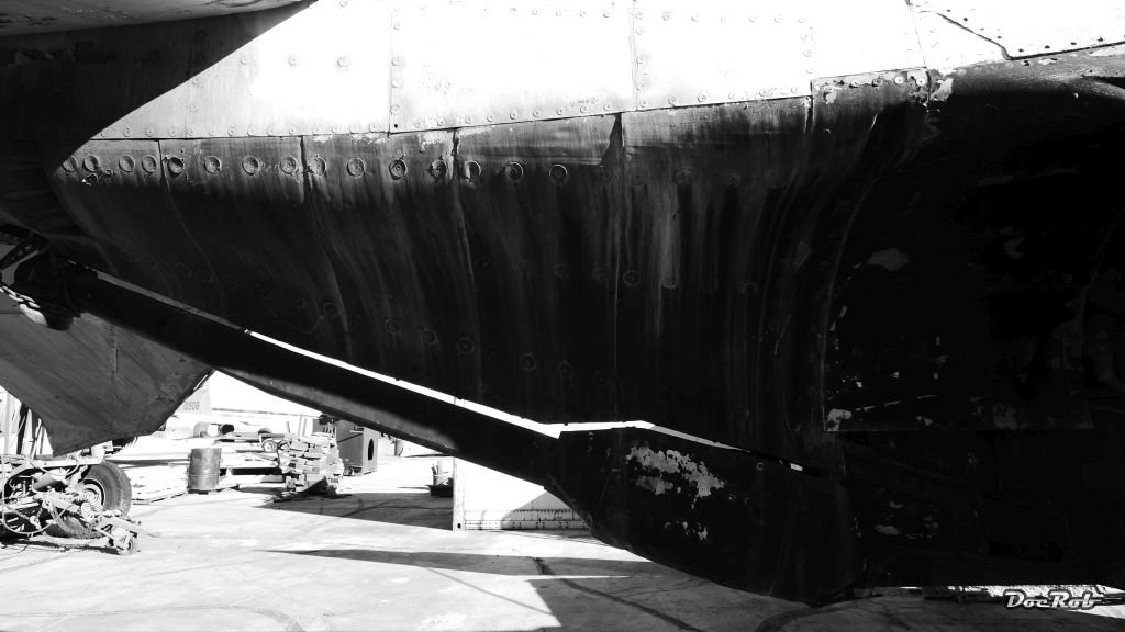
Must have been a scary experience, Ken. My F-4 was supposed to look newish without the abuse of over trying pilots . That was my bird: ... and that is how your Rhino looked after your flight? (I took the picture at Chino California some years ago) Cheers Rob
-
I spare you the smelly pics, the next two layers on the Kampfanzug were hairspray for my planned heavy sandblast chipping. I use the stuff directly from the can. For those, who don´t know the technique. I made a steel base layer, then hairspray and on top I apply the two tone camo. When everything is dried, I dampen the surfaces with water, where I want to chip, which activates the hairspray and loosens the adhesion of the two tone camo layers. With different tools, I can now scratch the top layers away. Next was the base layer of my planned camouflage, using Tamiya XF-64 red brown as the darker tone. It´s a bit bring to show all the layers here, but I did, to describe the process. Cheers Rob
-
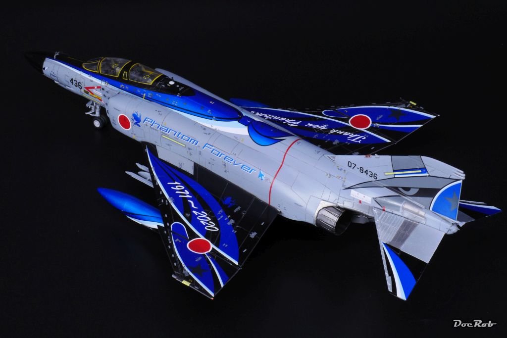
Don´t get me wrong, Ken, AK titanium sprays well, but it´s not very robust, but if you don´t mask on top, it works fine. Cheers Rob This is an excerpt from my Zoukei Moura Kai Phantom build for the area you mentioned: Some year end shiny glitter metal work was due today. The tail section of the Phantom got my preliminar interpretation of the real thing. I used different metal shades all from AK's Xtreme metal range. The upper areas beside the tail wings were sprayed stainless steel, along with the tail wing protection, where the middle part was masked off and sprayed gun metal. The protective sheets around the nozzles, where sprayed with titanium and accentuated with pale burnt metal. After all was dried, I did some soft panel picking with jet exhaust mixed with titanium, to create the illusion of not totally flat appearing sheets. All metal areas will be masked and later, after airbrushing the fuselage finally treated with some pigments and maybe panel liner, depending the overall look. One word about the formidable Xtreme Metal colors. On many occasions, I used them, they were very good to spray, have very fine grain and dry fast. I even went so far, because on my other builds they were very durable, to mask onto them with Tesa and Tamiya Kabuki tape without de tacking and had not the slightest lift at all, great stuff Happy New Year mi Amigos! Cheers Rob


