
DocRob
-
Posts
1,296 -
Joined
-
Last visited
Content Type
Profiles
Forums
Gallery
Events
Everything posted by DocRob
-
 Thank you Tim, it just doesn´t feel good not to be able to finish as planned. Nonetheless, there will be a place reserved in my shelf for the finished Cobra. The kit is indeed very heavy, but I haven´t weighed it. My guess is about three kilos. MFH provides spacers, to screw under the chassis to prevent the suspension to take the full weight. Cheers Rob
 -
Thank you Mark, there are still many aspects, I like about the Cobra build. It´s a fail to my eye, but not wasted. I never saw the mentioned lock pins used for the Cobra Coupe´s, I guess, it´s because the complete front opens angling to the front. There are the front hinges and then some sort of metal latch to keep it close at the sides. Cheers Rob
-
Hehe, 99% would be a great exaggeration, Kevin, but thanks for your supportive words. I will close the build as it is as soon as possible now, but I´m strongly motivated to do better with the next one. I have some more MFH test mules in my stash . It´s not the end of the world, it´s more about lessons learned. I may have taken on too much with the Cobra and my the next project will be a bit simpler, possibly a Formula 1 car. As I usually loose interest into a project, once finished, the frustration may vaporize later on, but the experiences and skills remain. Cheers Rob
-
Thank you Craig, the fit issue was not connected with the relief areas, which worked well and the intake funnels were not a problem anymore. There were different areas of the large cooler housing, which needed to be manipulated and possibly the prime culprit, I have a step of about one millimeter between the chassis and the front of the body, but there was no way to change that anymore. I will not spent more time to find a better solution, because I already did that highly concentrated for hours. Cutting away the hinges was the final measurement to my eye. I read on another forum, where somebody said, the bonnet to body fit is possibly problematic, so maybe I´m not alone. Cheers Rob
-
Thank you for your warm words, Yves. The bonnet will remain openable with two rivets need to be pulled out for removing the bonnet. At least, that´s the plan. I still like the Cobra, but I couldn´t fulfill one of my main goals, even when I had foreseen this to be a gamechanger right from the start. I always build models to learn something with every build. I learned among many other things, to show some dignity to a truly demanding build and prepare even better than normal. It will definitely not be my last MFH build, I tasted blood and hope this fail makes me stronger with other builds. Cheers Rob
-
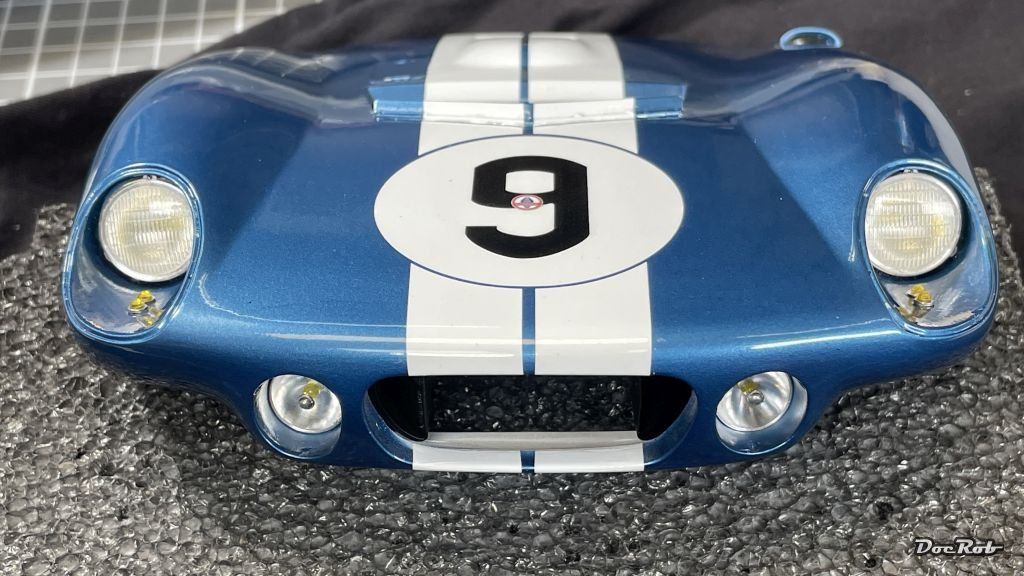
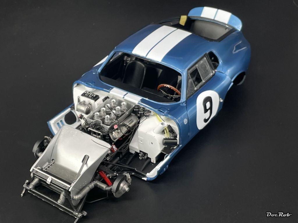
The Cobra build will go down as a fail for me. Nonetheless, I will finish it, but my attitude towards the build has changed and it doesn´t feel good, as I gave my best and am sure, it´s only my fault and not the kits. What happened. From the beginning, I feared the fit of the huge bonnet to the body to be critical and spent numerous hours in dry fitting and manipulating parts to reach that goal. When I finally came to the last dry fitting, after marrying the chassis to the body, I hit the wall again, it was not possible to close the bonnet properly. After hours of searching again for the obstructive parts, sanding, routing and grinding them to fit, I gave up and cut the bonnets hinges, the final measurement, which made the build a fail to me. I will only be able to remove the bonnet, but never with it´s purposed function. Nonetheless, I continued with outfitting the bonnet. I added the front coolers and headlights. These have a cast metal socket, bolted on from the inside and consist of finely turned aluminum reflectors. The bulbs are clear resin and I decided to paint them with clear yellow for a dot of color. The headlights then receive a PE and cast framing and were glued in from the outside. The lower lights got a tiny polished reflector glued into the middle of the clear part. I will skip the internal wiring, to leave the bonnet removable. Cheers Rob
- 225 replies
-
- 10
-

-

-
Your Porsche looks fantastic. I never would have thought, I would like it in yellow body color. I tend to buy more body color than needed, for the reasons you mentioned and who knows if a later batch is exactly the same. For the Cobra Coupe, I ordered four jars of 30ml (1oz) pre thinned Number Five color. I used only about two jars with four coats of paint. I need a second kit . Cheers Rob
-
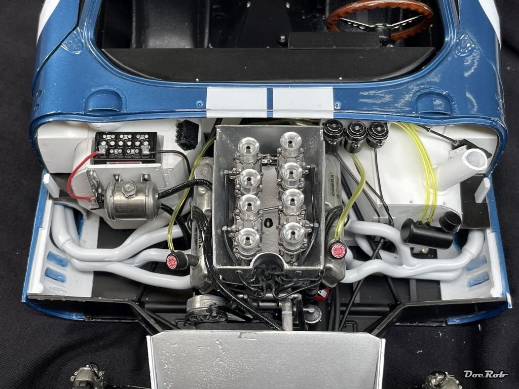
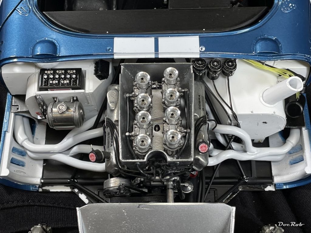
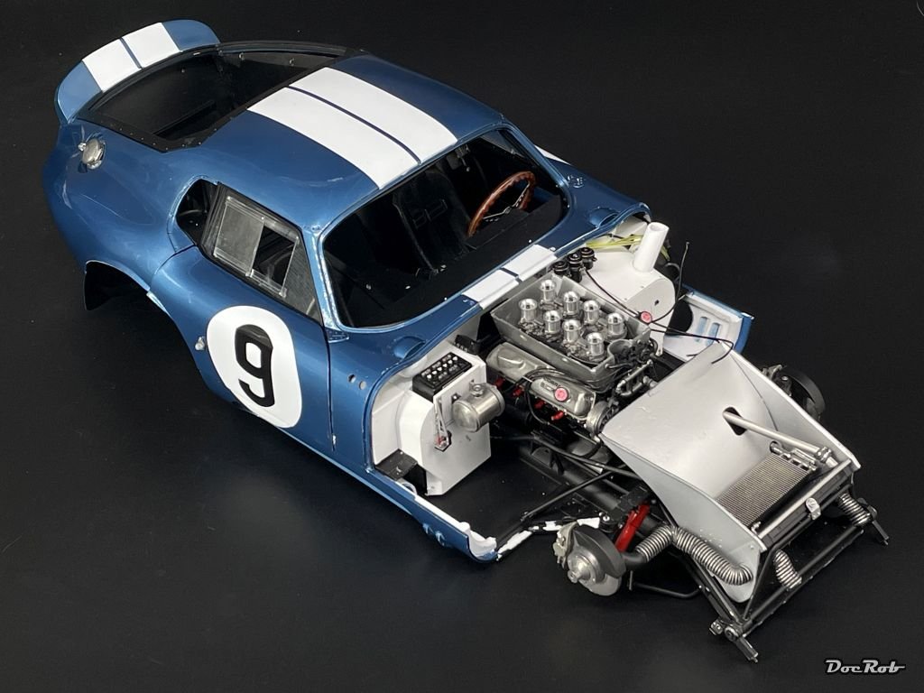
One day later and the engine bay is near ready. I added electric wiring, oil and cooling tubes and re glued the ignition wiring. I also made a lot of touch ups with white and black paint and added the fender fairings, which broke loose more than once. One tip for adding the tubes into pre drilled holes like the silver coolant tank on the left. I cut the hose diagonally and that made it easier to fiddle them in. Same goes for the yellow oil tubing under the stripes, which are really hard to reach. The small black oil reservoir on the right side is still not fit, because I lost the inner part, which I needed to break free for adding the manifolds. Cheers Rob
- 225 replies
-
- 12
-
-

-
Thank you Ken, I really enjoy to build complicated kits and test my patience and skills. I easily get bored without a challenge in modelling and always hope, I´m not putting too much on my shoulders. Cheers Rob
-
Muchas gracias amigos, it definitely took some time to figure out, how to add the manifolds , steering column and cage rods, even with the added manual sheet, showing the sequence. You had to 3D-fiddle the bulky manifolds in, always hoping not to destroy engine details. I have to re-glue many of the ignition wires, which were in the way and had to be sacrificed. The design of the kit is again a-maze-ing. I have no idea, how MFH designs these kits. Sure, they use 3D programs, but these don´t show, how it has to be build. The added page to the manual indicates, that MFH actually builds their models, which is good to know. Cheers Rob
-
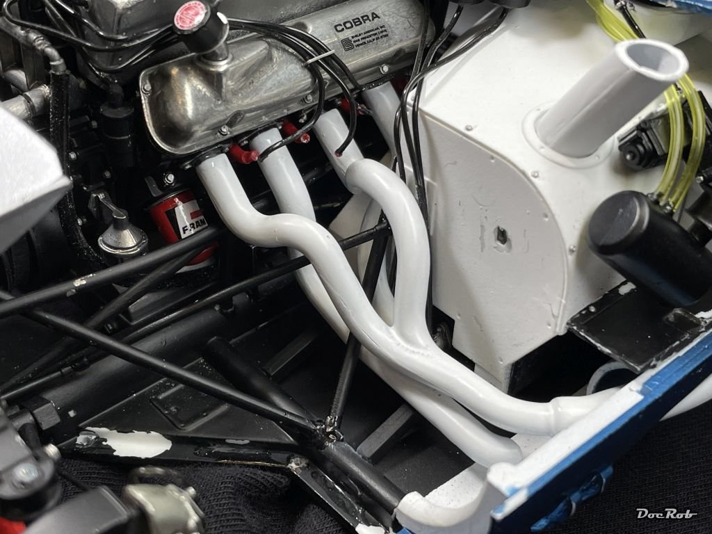
Exhausts and manifolds, an assembly, I didn´t look forward to, because it´s multiple parts in very confined space. I took my time, dry fitting the manifolds before painting. After airbrushing all in Tamiya lacquer matte white, there was no way around continuing. Fortunately there is an additional manual page provided by MFH, which shows the sequence, how to mount the parts. With the sketches in the normal manual, I would never had made it. Especially the right side was delicate, as there are frame rods and the steering column to add, which are all intersecting, it´s a true 3D puzzle. It took some time and some damages occur during the process, but somehow I got it done finally. Mind, these are bench shots without touch ups and repairs, which will be done after test fitting the side pipes. Cheers Rob
- 225 replies
-
- 13
-
-
-

-
I know that anticlimactic feeling as well Mike, happens to me all the time. During a build, I like to build up a certain grade of tension, which keeps me on the heels and drives me through obstacles during the ride. Crossing the finish line is rewarding, but I can only enjoy it, when I have an interesting follow up project in mind. It´s the same with good books to me. I don´t like to end one, without some other decent stuff in vicinity. One thing, which usually keeps me in a build is my dislike for the SOD idea. I hate to shelf projects, as I rate it as a kind of failure. I have a finished model´s picture in my head, when I start a project and I want to fulfill that image with all my abilities. I felt very bad about shelfing my 1/32 Arado 234 twice and was very relieved when I finished it two years ago. Same with the Duchess of Kingston, which I built like in great flow, hurdling all the obstacles, which were new to me, only to shy away from the rigging phase. That´s like an open wound and I have to close it soon. A hobby like modelling is about passion to me and that leads to various states of minds during a project and I try to keep each project on a demanding but satisfactory level. As I have no competition around in my isolated place, I´m always my fiercest competitor myself. Cheers Rob
- 47 replies
-
- 3
-
-
- Annapolis Wherry
- Chesapeake Light Craft
- (and 1 more)
-
Nice little craft in very large scale, Mike, this should be interesting and hopefully refreshing, as you wanted it to be. Cheers Rob
- 47 replies
-
- 3
-
-
-
- Annapolis Wherry
- Chesapeake Light Craft
- (and 1 more)
-
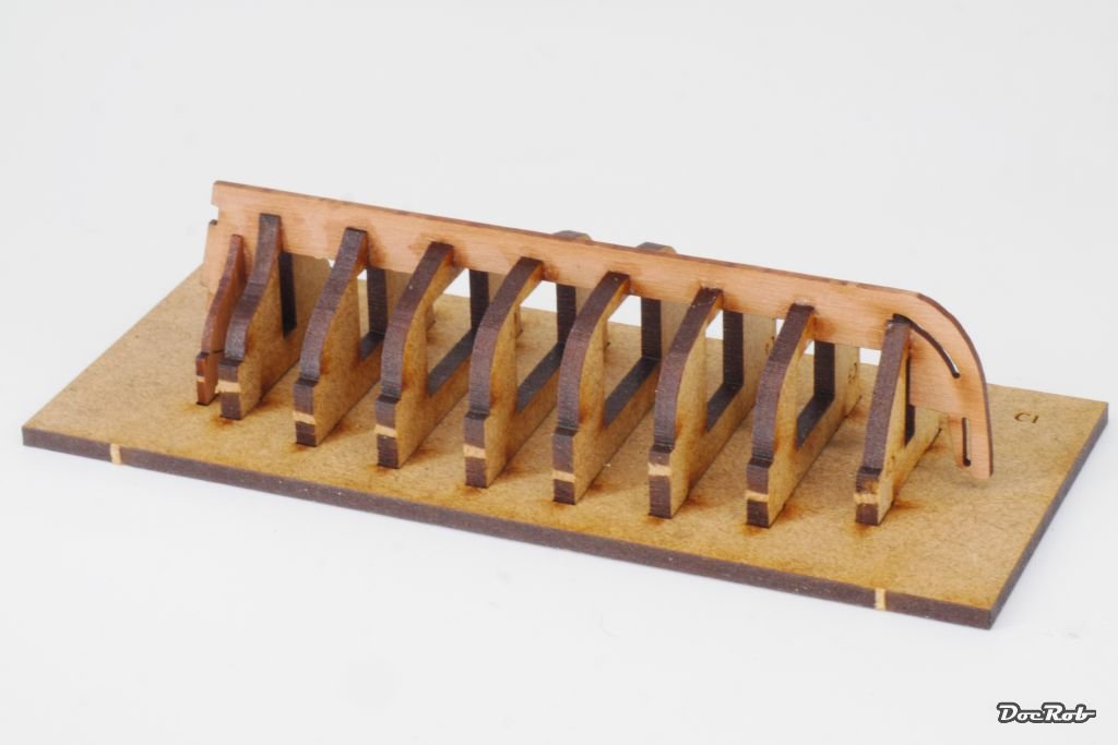
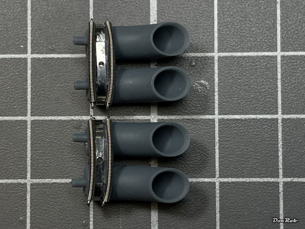
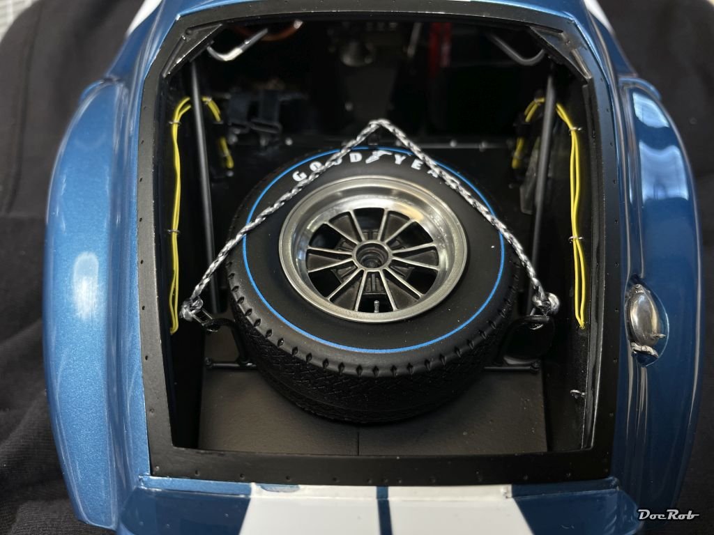
The rear section got finished with the spare tyre rack. I´m not sure about the rope and have to find some pictures of the real car to verify, but this is, how it is shown in the manual. I don´t want to have a collision with that huge heavy tyre behind my head. Next, I started to prepare the exhausts. The manifolds are made from white metal, which has to be fitted into the confined space of the engine compartment. The side pipes are produced from resin and the exhaust ends are 3D printed which added PE- and rivet fittings. Every time, little coil springs are involved, it gets creepy. These buggers are really hard to fit into the PE fittings properly and you don´t want them airborne. Anyway, here are the end pieces. Cheers Rob
- 225 replies
-
- 13
-
-
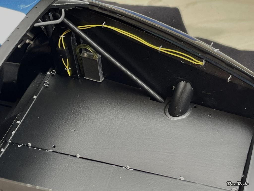
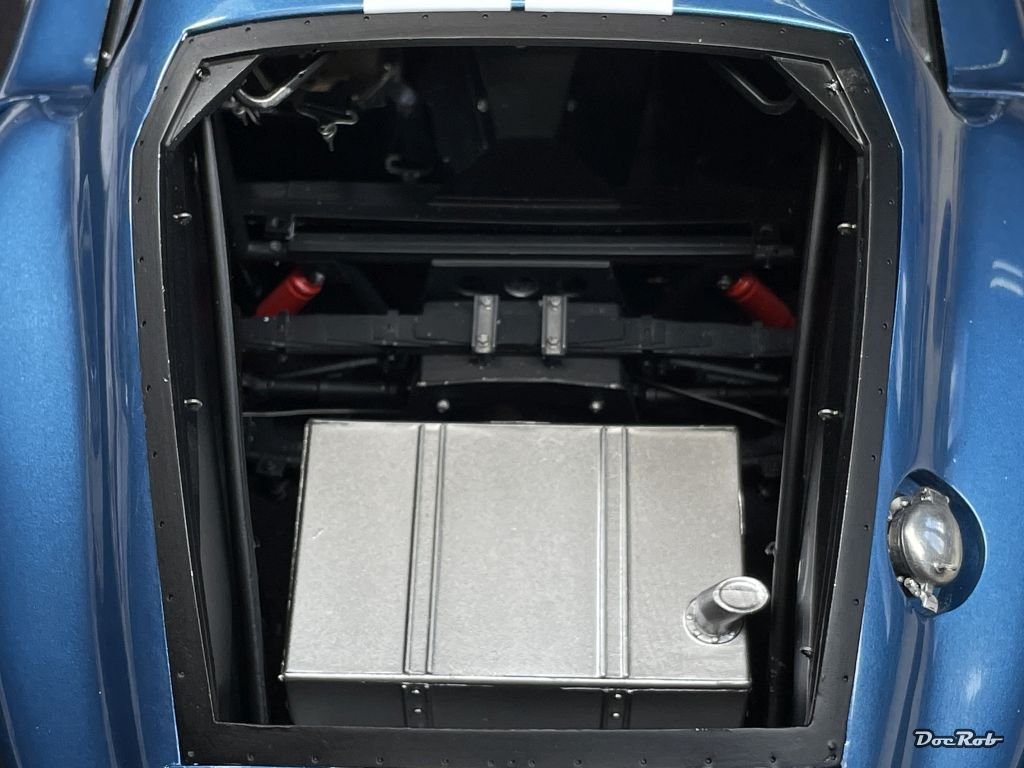
I decided to let the implications of the exhaust system stew for a bit and went to the rear interior area. There is an internal framing down under the tank, which is connected with the chassis as well as the body and it fits like a glove. The framing holds the tank, which I only painted in aluminum without detailing, because it will never be seen again. Next, the right and left rollcage bars were added, not too easy, but they also fitted perfectly, which shows how good the engineering is. The difficulty with these parts, it´s all black in there and you have to use an extra light for proper orientation. Now the tank got covered with a two peace (smart) flooring, which also has a lot of fittings for the seat belts and seat supports as well as rivets added. I then added the wiring for the backlights onto the rear air ducts. Unfortunately not enough yellow cable was supplied and I decided to drill a hole and let the cable end there. Last was the small oil tank with it´s tubing and now it will be time to install the spare wheel. But this will be done after some touch ups. Cheers Rob
- 225 replies
-
- 12
-
-
Thank you Ken, in the harder moments the build is a test of patience, but the fun parts are predominant, it´s all part of the experience. At the moment, I reached a phase, where all the work intense sub assemblies have to be mounted to together, which is a bit nerve testing somehow. Spaces got more and more confined and the really heavy kit becomes difficult to handle. On the other hand, I can see a finish line, which is quite motivating. Cheers Rob
-
Fantastic, imaginative and well executed, Greg. There are so many details to catch the eye and nonetheless, everything blends together perfectly. In other words, I love it and enjoy the creativity you show here. Cheers Rob
-
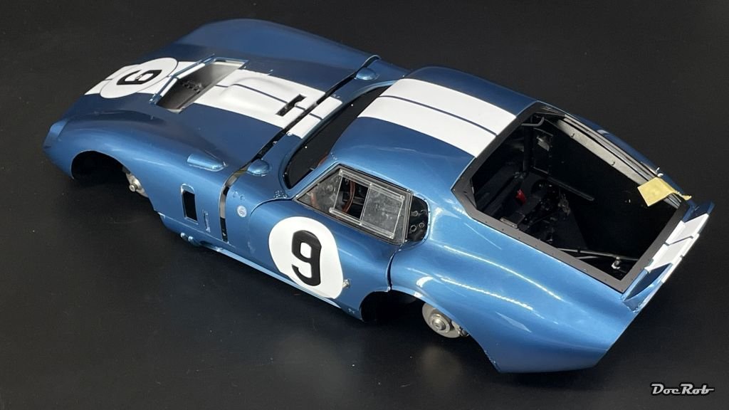
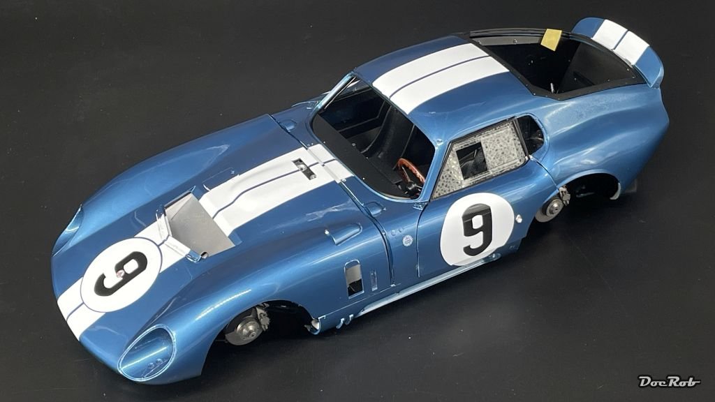
Today, I had the second attempt with adding the body to the chassis. Yesterday, I tried to identify the obstructing parts and gave them a little workover. This is not like you can pull the body off the chassis as often as you like. All the tolerances are really tight and it involves a lot of bending causing nasty sounds to get it right. When the body was halfway into position, I used a lot of finger force to push everything carefully into place and added screws into pre drilled holes. There were not too many damages to report, only some more scratches and one or two parts knocked off. It´s hard to describe, but there are so many elements all around, which have to fit, I expected worse, but it was no walk in the part and it´s about make or break with the Cobra. The engineering is fantastic, I don´t know how they are able to do it, this is not the average " I close the fuselage of my plane job". Attentive readers might see, there were parts removed from the firewall. This is necessary due to the preparation for installing the exhaust system, the next obstacle in this confined space. There is an additional sheet in the manual, showing the sequence of every part, but I couldn´t make it properly during test fitting. Anyway, I´m lucky, I managed to marry the body to the chassis without too much fuzz. The bonnet is only laid on and the doors need some fine tuning later on. Cheers Rob
- 225 replies
-
- 17
-
-
-
-
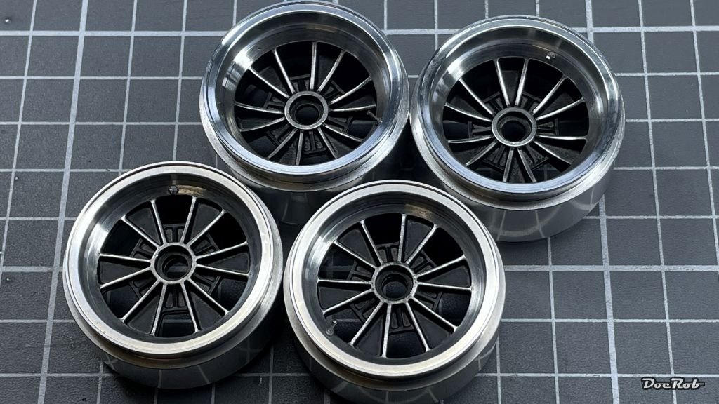
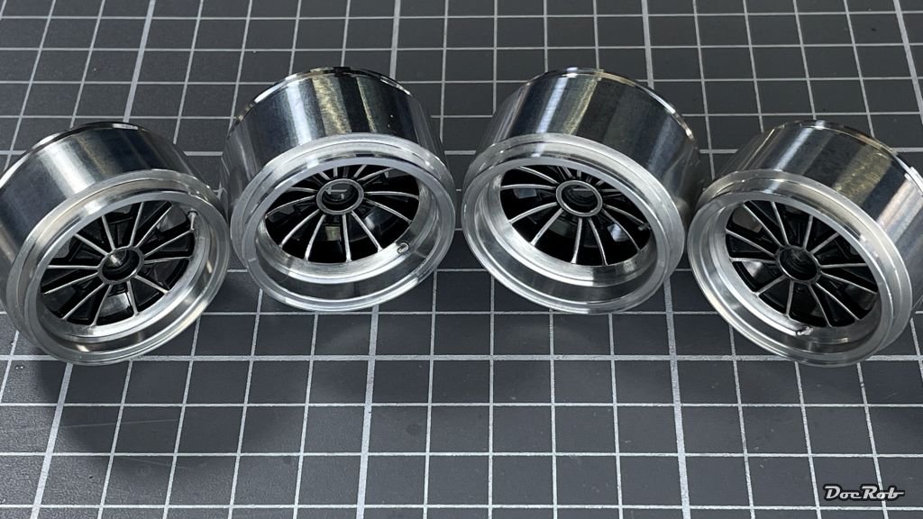
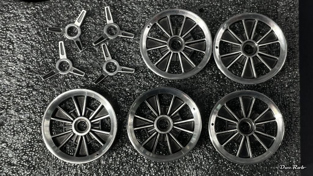
I like them too, Egilman. The extra work was well spent. There were cast imperfections visible and the near polished look of the turned metal rims would have contrasted sharply against the greyish casted inner parts. Luckily the white metal MFH uses is easy to work with and polishes relatively fast. Cheers Rob
-
I will take a seat here Andrew, I always liked the quirky Lysander a lot and also found the stories around this airframe very interesting. In my youth, I butchered a Matchbox 1/32 Lysander and always wished for a decent large scale release. You can reduce the risk of fogging up the clear parts with dipping them in Future / Pledge. It also enhances the general transparency of the parts. I have a jar of Pledge for this task, where I dip the clear parts in and let them dry properly, clipped to a small holder, so that the excess Pledge samples on the lowest corner. There I touch the edge with a toothpick, to get rid of the excess Pledge. This has to be done maybe thrice over the first half Hour of drying and then you are fine. Cheers Rob
-
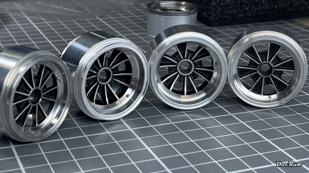
I hope, I can de-diffuse the appearance of the rims with some new pics, Egilman. I finalized the rims with installing the painted and polished center parts into the turned aluminum rim. I also added the air valves, but didn´t add the tyres for now, because I fear, the CA fumes might affect them. Cheers Rob
- 225 replies
-
- 11
-
-
-
Thank you Kevin, it´s the first time, I use this method on metal rims. I tried similar things during my Crocker build, but with smaller parts and usually polishing away the dried color with abrasive fine sanding sponges. I didn´t want to leave sanding residues onto the wheels, therefore, I chose the swiping method. Here I thought, the adhesion of the Tamiya Lacquer wouldn´t be too god without primer on polished metal. The curing time was thumb measured, with hopefully dry paint as a result, but not thoroughly hardened, to have perfect transitions without risking breakouts while cleaning the rims off. When I mask objects for airbrushing with kabuki tape, I let the paint dry for only some minutes, before removing the masks. This way, the paint borders are cleaner and smoother. Cheers Rob
-
Not the best picture for sure, Egilman, it was only a fast phone snap off the bench. I promise to do better, when the wheels got assembled. Cheers Rob
-
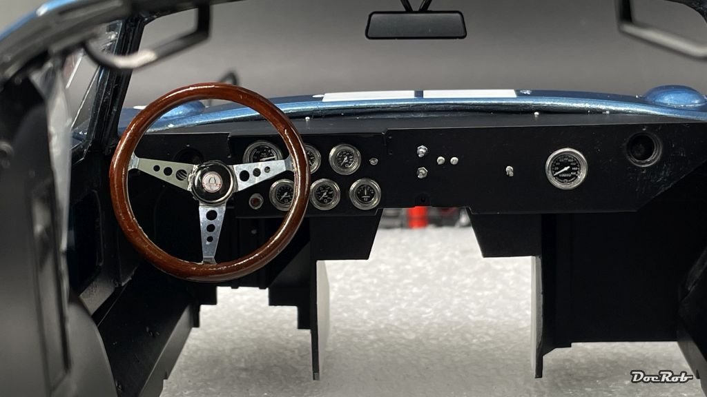
Today, I made the first attempt of a very crucial step, with marrying the body to the chassis. As you can imagine, there are a lots of contact points on the chassis, around the firewall, under the instrument panel, the rear body framing, the rollcage, ...., to cut it short, I failed. Now I´m inspecting everything for color abrasion, which might show problematic areas, which may need to be tweaked. Fortunately, I didn´t brake too many parts, but the rear hatch framing needs to be reinstalled. I´m very happy, that I didn´t follow the manual with the rear hatch window and windshield installed. before joining the chassis and body. It would have been a nightmare to handle the heavy kit with these mounted. Before all this, I finished the shoulder straps of the seat belts, which is an easy task with the supplied PE buckles, belt material and double sided tape, which holds the belts perfectly together and in place. I finished the steering wheel with a coat of Tamiya´s clear orange onto the dried oil colors and then assembled the PE and center knob. That was more difficult then expected, but finally it worked. The clear center part is made from resin and was not clear at all from the beginning and had some tiny scratches. I polished the lens with Tamiya´s polishing compounds and adhered it with Pledge on the decals. Next were the wheels, which were sprayed with Tamiya´s semi matte black (LP-5). After two hours of drying time, I didn´t want the paint to cure too much, I swiped the rims with cotton swabs and cotton cloth, slightly dampened with Tamiya lacquer thinner and cleaned off the polished areas. Cheers Rob
-
Juten Morjen Joachim and welcome to MSW. It´s good to see somebody here from my old hometown and place of birth. Cheers Rob