HOLIDAY DONATION DRIVE - SUPPORT MSW - DO YOUR PART TO KEEP THIS GREAT FORUM GOING!
×


Stockholm tar
-
Posts
866 -
Joined
-
Last visited
Content Type
Profiles
Forums
Gallery
Events
Everything posted by Stockholm tar
-
Eamonn, Great job, she's looking very nice. So, on to the mystery's of joggling, huh? Will you be painting the frames of the gunports red too, and as well even?
- 1,039 replies
-
- 1
-

-
- ballahoo
- caldercraft
- (and 2 more)
-
Deptford Yard Circa 1774 (England )
Stockholm tar replied to edbardet's topic in Nautical/Naval History
I had an e-mail from the organisers of the petition, which I signed a while back, a few days ago. Apparently the Mayor of London, Boris Johnston, has passed the proposed development scheme – but with the proviso that the developers incorporate both the historic dockyard and Lennox project, and the Sayes Court Garden. Not quite what either parties wanted, but it seems the Mayor is attempting to satisfy both camps. The petition by the way is now closed. -
What is the name for the netting under the bowsprit
Stockholm tar replied to HKC's topic in Masting, rigging and sails
HKC, So far as I know and heard, and I have sailed on a few square riggers, it has always been called just that – the bowsprit netting. I can't answer your second question, but I'm sure someone will come back on that. -
Hi Mike, You seem to have put a lot of thought into your plans and, following your good work on the Badger, I can only think this going to be even better! Perhaps you might also provide your own flags when you get to that point. As per usual they are incorrect, so something to bear in mind. This is going to be an interesting build.
-
Deck planking
Stockholm tar replied to latestarter's topic in Building, Framing, Planking and plating a ships hull and deck
Latestarter, I prefer to plank the false deck when it's in place, although I believe some opt to plank it beforehand. You have to remember that the false deck will take up the camber of the beams underneath when fixed, both fore and aft and athwartships, and this can be quite noticeable on some ships – ie. when fixed, it will not normally be the dead flat it was straight from the box. I think if you glue the planks before you fix the under deck, plus adding the caulking between them, you might get some of them opening up later along the seams due to stress. There are also other considerations, such as the joggling of the outer planks into the margin plank (around the deck edge), hatches. etc. It may look easier to plank off the model, but I'm not sure that it is. -
Then again, can we actually trust midshipman Dillon's account? He says that at times the lower deck 'was at times so completely filled with smoke', so how can we be sure the guns 'nearly kicked the upper deck beams' as he says? With the 'excitement' of battle, may he not be 'guilding the lily' somewhat in his account – which we can put down to the exuberance of youth? Also, how much later after the battle did he record this – long enough for him to add a little embellishment perhaps? Of course, he may be telling the truth – but I'm not 100% convinced.
-
RMC, When I came to the lettering on my Sherbourne, I opted to use the kit lettering, but attaching them needed a little thought. As opposed to your Vanguard, the space available on the stern was limited, so placing the letters was quite critical – not only centrally, but also leaving a reasonable space between the letters. I originally thought, naturally, to begin on the left, but then I might have too much space left over on the right – which certainly wouldn't look good. After a bit more thought, I decided it was better to start with the middle letters and work outwards, leaving a suitable space between them, and using the position of the rudder as the central point. This would then leave the same amount of space, outside the name, on each side, and it worked well. Sherbourne, like Vanguard, has an even number of letters (although ten as opposed to eight), so the 'b' and the 'o' had to go equidistantly either side of the rudder. You might do the same with the 'g' and the 'u' of Vanguard. The other letters naturally follow, until the first and last letters are reached. I think it will work. There is a big difference in size of course between the two ships, so you should probably have quite a bit of space either side of the name. I had a look at photos of the stern of the Victory, which is nearer to the Vanguard in size and, although the letters are quite large, they don't of course cover the whole stern. She has an odd number of letters (one less than Vanguard) and the 't' is central under the middle of the stern windows. The name follows the curve of the wardroom windows. Btw, the letters are Roman font.
-
Arthur, Good for you! Kevin, Stick to your guns, you're model is amazing!
- 1,319 replies
-
- 1
-
-
- caldercraft
- Victory
- (and 1 more)
-
Gregor, Looks good – I wouldn't like to be the smuggling lugger on the end of that lot, at close range! As for the 'Pickle's pumps', I'm sure ship fittings were often recycled from other vessels.
- 210 replies
-
- 1
-
-
- Sherbourne
- Cutter
- (and 5 more)
-
Anyone thought of building a plank on bulkhead kebab shop? No? Drat! Eamonn saw through my scheme to pursuade him to go for scale planks! Btw, Dee Dee, I don't think I said anything about Poly – wipe on, wipe off, perch sitting, or any other sort – but if it works for you...
- 1,039 replies
-
- 2
-
-
- ballahoo
- caldercraft
- (and 2 more)
-
Nice work Eamonn, especially the last shot of the telly – sorry, transom, half hidden though it is by your delightfully arranged rubber bands. Good advice from Nigel to keep your planks straight, as scale length planks tend to need a bit of linear adjusting. As for your last paragraph in post 277, I have absolutely no idea what you are referring to.
- 1,039 replies
-
- 1
-
-
- ballahoo
- caldercraft
- (and 2 more)
-
Mike, Many thanks. Glad you enjoy my 'turorials' – I go for the carrot and carrot approach! So, after your brilliant Badger, it's to be (if I remember right) the Unicorn AND the CM – perhaps with a touch of Pegasus thrown in? That must be worth watching for.
-
Popeye, Thanks for the compliment. As for the other, no not really – although my ME also kicked in. It's the worse time of year for it, I'm afraid. I see you're going great guns on your builds.
-
Gregor, An interesting theory of yours, regarding the fitting of carronades. However, I'm not completely convinced they were suitable for a vessel of Sherbourne's small size and scantling – even if not Sherbourne herself. (I actually doubt Sherbourne herself was fitted with carronades, which in any case would have been towards the end of her life, which I think was around 1784. That's only five years, and I'm sure there were initial teething troubles to overcome. I think I'm also a little with Jan on this one as, although the carronade was of course lighter, they fired a much heavier shot and we don't know what impact the recoil would have had on the timbers and other fittings, not designed for such treatment. I think these cutters were quite strongly built, but it would be good to know if there is any written evidence that carronades caused stress problems in small vessels. Looks good though, I admit!
-
Timmo, That is one very nice headrail – so much better than in the kit! I think it was certainly worth the effort.
-
Nils, Thank you for your kind words and continuing interest. I often think these smaller vessels are as interesting, if not more so, than the larger types such as the Victory. Eamonn, I will endeavour to do as you say!
-
Hi Eamonn, Thanks. Yes, this instalment was a little late in coming, but as you can imagine it was a bit involved – and there were a few other things, not model related, taking up my time. Al the best.
-
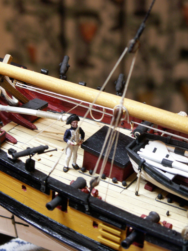
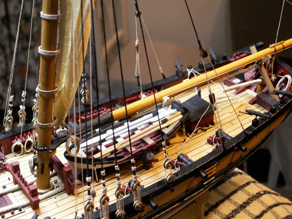
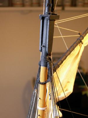
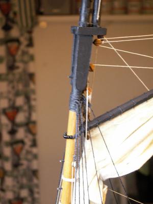
There are only running backstays provided for in the kit plans. However as mentioned previously many cutters had both running and standing backstays, as shown on the AOTS plans for the Alert, and I also included them. Having fitted the standing backstays, I decided to move the position of the running backstays further aft, so as to give a little more practical distance between the two. Thus the straps and eyes are situated on either side of the after gunport. Inside the bulwark on either side, inboard of the forward strap, I fitted a small shot garland – with a single belaying pin at its forward end for the falls of the tackles. Since the model will be as she might appear in harbour, I opted to have both of the running backstays set up. At sea, normally only the windward one would have been in use, particularly when the vessel was ’running’ with the wind aft or over the quarter. The tackle of the leeward backstay, and hence the stay itself, would have been moved forward to a convenient place on the rail, from where it would not have impeded or chafed the main sail. When the cutter tacked the roles would have been reversed, the windward backstay then becoming the leeward, and vice versa. The tackles were therefore most probably fitted with hooks, which fitted through the eyes on the top of the hull straps. I used four of those provided in the kit. The first small job was to fit two eyebolts just aft of the standing backstays, for the running backstays when they were not in use, painting them black. The backstays themselves are in three sections. The standing part, which runs from the masthead to approximately two thirds of the distance to the deck, having a single block in its end; the running part, one end of which is hooked to the after eyebolt on the main rail, passes forward through the block in the tail end of the standing part, and is then seized to a long-tackle (LT) block at its other extremity; the tackle, the fall of which runs from the tail end of the LT block, and reeves between it and a double block on the eye of the forward strap on the rail, before belaying to the pin in the shot garland on the bulwark. The following mainly describes the rigging of the running backstay on one side of the model, which is of course duplicated on the other. To take the standing part first, this is of 0.7m black waxed thread, with a 5mm block seized into one end. Both blocks were stained and the seizings made, with the help of my new seizing machine – and they didn’t turn out too badly, for a first effort. I made both the larboard and starboard together, to ensure they would be of the same length. The upper ends were then seized around the mast head, as for the other backstays, the starboard first. Again I had to ensure that the same amount was doubled and seized on each length, in order that both blocks would be approximately in the same place when rove – and I breathed a sigh of relief to find, when they were in position, that they were exactly level. Moving on to the running part I used 0.5m tan thread for this, and again both sides were made together. First each hook had to be filed somewhat to fit satisfactorily through the eyes on the hull straps, before the thread was seized to them. The hooks were painted black after seizing as being somewhat easier to hold. The line was then lightly waxed and the hook connected to the after strap on the rail, the end of the line being threaded forward through the single block on the standing part. (I should perhaps mention here, that all the hooks were passed through the eyes in the straps from the inboard to the outboard side.) The end emerging from the block had now had to be seized to a LT block. These are not included in the kit, so two suitable 7mm LT blocks were purchased. They proved generally satisfactory in both colour and shape, although I had to to file out the grooves for the strops. Now we come to something of a ’Heath Robinson’ moment. I estimated that the top of each LT block had to be seized about 2cm below the base of the single block at the end of the standing part, to look right. The problem was in getting the blocks on both backstays in a similar position. I eventually hit on the idea of using a thin stick – and a small blob of blue tack (well, I did say it was HR). First I tensioned the line coming from the single block, using self-closing tweezers (they are ideal for such weighting jobs), picked up the LT block on the blue-tacked end of the stick, and ran a very thin bead of glue down the visible groove with a pin. Then, holding the stick horizontally from the opposite side of the model, I offered up the LT block (larger end uppermost) to the line of the running part nearest to me, i.e. across the model – at the same time simply (?) measuring 2cm below the single block, with a ruler! This ensured I could see that the groove, and hence the glue, went directly against the line in the correct place – and that the latter didn’t spread itself liberally, unseen, all over the block! Once the LT block was attached I used a light clamp, on both it and the line, until it was dry. Then it was just a question of glueing the rest of the line around the groove in the block, leaving a very short tale which was glued to the line above it. This was then seized and the job was done. The tackle reeves between the LT block and a 4mm double block attached to the forward strap on the rail (again the latter blocks are not included in the kit). I attached the hook to the block with a thin wire strop, painted black, twisting a small loop into it at the base of the double block to accommodate the strap eye. As with the LT blocks, the double blocks were well made apart from the groove for the strops having again to be filed out. Little had also to be done to the sheave holes, apart from pushing a pin through them to be sure they were clear. The fall was 0.25mm tan, waxed thread, the end being passed with a needle through the strop at the base of the LT block, and fastened with a knot and a small drop of glue, the latter applied with the end of a pin. The fall was then rove between LT block and the double block, from the outer side to the inner side, and coming off of the upper sheave of the LT block. The fall on the starboard side was belayed to the pin in the shot garland, and finished off with a coil. That to larboard has been tensioned, but not belayed, it being held by a drop of glue in the sheave of the double block where the line emerges. I intend one of the crew figures to be hauling on the fall, being at the right angle, so this has been left until he is painted. I will probably post a photo of him later, when in position. That just about finishes off the standing rigging aft of the mast, and the ’action’ now moves to the fore side – which at the moment is looking distinctly bare. To finish, and as requested, I've added a couple of photos of the 'situation' at the lower masthead, or the spot where the shrouds meet: Next time: the strops and blocks for the lower yards, and the fore staysail halliard.


-
Mike, I can only add my congratulations for your wonderful Badger. Well done indeed! Looking forward to your next build, be it Unicorn or CM. Btw, will there be a case? I'd hate for all that nice work to get dusty.
- 153 replies
-
- 1
-
-
- badger
- caldercraft
- (and 1 more)
-
The vessel in question here is the Racehorse, a small RN bomb ketch/sloop. I somehow doubt that either money, or time, would have been spent in decoration beyond the practical – especially in the work she was engaged in, and unless there was a very good reason for it. White-tipped yards, bowsprit ends, etc., may have been usual across the pond, ie. in America, but I'm not sure that would have been the case here at that time. I have no idea where the manufacturers obtained their information (I suspect it’s a whim on their part) but I would paint the yards all black. I can find very little information about painting yards although, as I said, black seems to have been the usual colour in the RN. Former curator of the Victory, Peter Goodwin, mentions in his Victory ’manual’ that the black was usually a mixture of paint and some form of preservative, such as varnish, which would seem logical. Btw, the manufacturers’ blurb often contains the mis-information that a certain young Horatio Nelson served aboard the Racehorse, presumably with an eye to selling the kit. Although the vessel was part of the same expedition to the Arctic in 1773 in which midshipman Nelson took part, he was actually on the books of a similar sloop, the Carcass.
-
Eamonn, Was that why you took, erm, early retirement? Ok, I see what you mean about the 'squared off circular thing that attaches to the outside of the transom'! I don't know what it's called either – 'transom surround' perhaps? Not to worry though, we know what you mean now. Yes, I would plank the transom. I did that on the stern of my Sherbourne, and it looks good – besides making my own 'squared off circular thing that...'
- 1,039 replies
-
- 1
-
-
- ballahoo
- caldercraft
- (and 2 more)
-
Eamonn, I would imagine, by the time Amazon (if ever) manage to sell one of those cans, it will be rock hard and well beyond its use by date! Good going on your planking – I'm sure we'll be rewarded with a pic soon, perhaps when you've finished the transom 'decoration type of thingy'. (I must say here that your nautical expressions are coming on in leaps and bounds.) Btw, you sound most apologetic that the Clamps, Pegs and Pins are off...
- 1,039 replies
-
- 1
-
-
- ballahoo
- caldercraft
- (and 2 more)
-
Although I don't know of any written evidence I believe the yards of 18th/19th cent warships, British ones at least, were usually painted black. However, I have never read or heard of the yard ends being painted white. To me, that sounds more like 19th cent. merchant practice. Stun sail booms on the yard arms however, if fitted, were often left natural (see the Victory). I think the yards of the Racehorse would have been black.
-
Peter, She looks superb, well done. Another cutter for the growing fleet on MSW! I look forward to seeing more.