HOLIDAY DONATION DRIVE - SUPPORT MSW - DO YOUR PART TO KEEP THIS GREAT FORUM GOING! (Only 24 donations so far out of 49,000 members - C'mon guys!)
×


Stockholm tar
-
Posts
866 -
Joined
-
Last visited
Content Type
Profiles
Forums
Gallery
Events
Everything posted by Stockholm tar
-
Nenad, I do agree with you on that point. I used to visit the ship quite often when I lived in England, and whenever I happened to be in Greenwich. I was a member of a traditional sailing club, Mariners International (now sadly defunct) and we used to hold our annual dinner on board, on the tweendecks, in the 80's. This was then followed by a suitable lecture in the hold, surrounded by the aforementioned figureheads where they were then displayed. Before hand, we met up for a drink in the nearby pub, the Gypsy Moth, and often walked around the ship. I do believe one could gain a better impression of her lines previously, particularly from the bow, and when looking down into the dock. Unfortunately that is largely now lost by the 'sea' which I think, btw, has far too many criss-cross bars to look effective. Anyhow, what's done is done, I suppose...
-
Nigel, Interesting you worked on CS during the restoration. I was in Greenwich last year and visited her. They've done a good job, but I'm still in two minds about the glass 'sea', although it does make for a usable space in the bottom of the dock. I loved the clustering of the old figureheads at the bow end, very spectacular. Having tea in the cafeteria under the hull, I was examining the plates. Even though muntz metal, I think they are too bright and could have been dulled down a bit, as I can't believe they were as bright after a few years service.
-
Monello, This looks like an interesting project! Besides the book by McKay, you will probably find the 'Anatomy of Nelson's Ships', by C Nepean Longridge, most useful. Despite the title, it is about his (rather smaller scale) model of the Victory that he built and now in the Science Museum in London, but not (unfortunately) on display. You'll find a clip or two of it on Utube. Although originally written in the the 1950's, it contains line drawings and photographs – and is still considered almost as the 'bible' on the Victory. Another useful book is 'HMS Victory – Her Construction, Career and Restoration', by Alan McGowan. Lots of detailed drawings and info there too, plus interesting text about her restoration over the years. Regarding your last post, all strength to your arm – or is that your power tools!
-
Les, I might have known you had the book! I believe it is considered one of the better ones from AOTS, and in fact Marquardt would seem to have been quite thorough when researching the ship, as witness this in-depth article I found on line: http://karl-heinz-marquardt.com/reports-of-karl-heinz-marquardt#beaglerevisited As regards Mamoli's model, the reviews of it I have read don't consider it to be much like the original ship – it does look a little like the Bounty – so no real surprises there. As you've probably read Beagle was converted from a ten gun brig, a class of which there were many, so the gunports would already have been there from those days. She also seems to have carried some light guns on the upper deck (so the model is not completely wrong) and the the bulwarks would appear to have being been planked, as I mentioned – which would provide for the gun tackles to be fitted. Your point about her being before Darwin's voyage is interesting, in that there are no aft davits for the surveying boats which were fitted during her refit. However, I would have thought that most kit firms would want to model the ship at its most historic moment – even though they often don't get the details right!
-
Bluenose, I would seriously consider acquiring the book about the Beagle in the Anatomy of the Ship series. Many do not believe these books are that accurate but, as has been said, they certainly show more detail than the kit plans. It is also written by a recognised authority – Karl Heinz Marquardt. A study of the cover of the book, indicates that the bulwarks in way of the guns are actually planked, the supports shown on your plans being on the outside of this. I had the Airfix kit of the ship when I was younger, and don't remember open bulwarks on that either. Planking the bulwarks should solve one part of your problem – where to attach the breech ropes and side tackles. There should also be a ringbolt, positioned behind each gun and close against the hatches, for the running in tackle. The book will most likely show all this. However, the book also shows that there were no guns in this position on the upper deck, but were below as the gunports indicate.
-
Puckotred, As Mike said, interesting build, but I too am surprised at how few frames she has. She should really have many more, to give the hull the correct shape, as it is obvious that a plank is going to go the shortest route between frames – ie. in a straight line, if it's allowed to. Some of the other methods used are surprising too! Good luck with her, I'm sure you'll find solutions! You and Mike keep warm, with these cold winds!
- 113 replies
-
- 1
-

-
- bohuslän
- nordic class boats
- (and 1 more)
-
Don, You are right, this is a copy, although I know nothing of Hogg. The original of Nelson was painted by Lemuel Francis Abbott (1760 - 1802) in 1797, and is quite a well known portrait. Nelson, then a rear admiral, had just lost his right arm at Tenerife and so it was still quite painful when he sat for the artist. He has captured Nelson quite well, and you can even see the pain on his face. I think Abbott painted a number of likenesses of Nelson, some with a hat and some – as here – without. However, his later paintings showed a deterioration of his technique, as he gradually became insane. I believe it is thought the artist may later have committed suicide, although I am not sure about that.
-
Nils, When I clicked the like 'button', I wasn't of course referring to the first part of your post! All I can say about that is: 1) It happens, usually at the most awkward moment; 2) I find a few choice words often help; 3) when you've calmed down a bit, you start all over again... sigh.
-
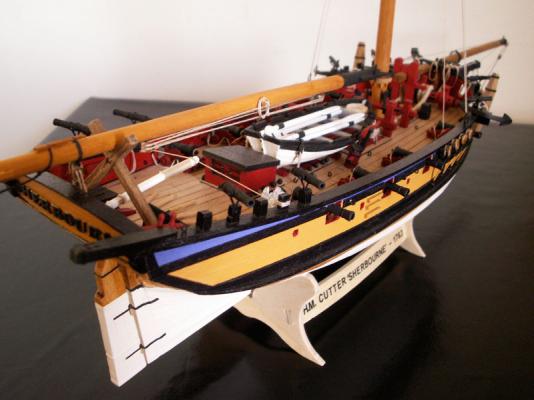
Nils, just been catching up with your log, and have to say that Pegasus is looking tremendous. Yes, the aligning of the deadeyes is a bit critical. I used the length-of-string method on my Sherbourne, worrying that all the deadeyes would be at the right angle. Lo and behold, when it came to actually rigging the shrouds – they were! I breathed a sigh of relief then, I can tell you! With all the forethought you've put in on this, I don't think you'll have many problems.
-
Nils, Thank you. I have to say she catches my eye every now and then! Popeye, Thanks for the information. I'm sure that'll be a great help when I try it with the other figures.
-
Popeye, Thanks for your kind words. I did have a slight suspicion that someone might have come across this paint problem before – and solved it! Well, I'll try my solution first, to see if that works. Looks as though it worked for you, but I'm wondering whether it wouldn't be better to mix it in with the paint first, rather than brush it on afterwards. I have an idea that would work best. What do you think?
-
BE, Thanks. If I can get anywhere near your brilliant Pegasus, I'll be well pleased. Still some way to go, I fear!
-
I've been wondering about Jeff for somwhile, since I have the kit too and have been following – although work has stopped on mine for the time being. It doesn't look as though he's posted since 2nd January. I hope he's ok. So Jeff, if you read this I hope you can respond. Steve, I believe that's all there is in his log, since I think the crash happened before. As far as his progress goes he's made a few good changes, and its certainly an improvement on the kit straight-from-the-box approach! Let's hope he can return to continue.
-
No Ratlines on Revenue Cutter Dallas?
Stockholm tar replied to RichardG's topic in Masting, rigging and sails
Couldn't it just be that the ratlines are just not shown on the plans? Probably all who consulted them would have known what ratlines looked like, so there was no need to show them. The shrouds are drawn, of course, to illustrate their positioning. I think I agree with Frankie here, as I can't imagine a vessel with yards having no ratlines. I suppose however, it is possible. -
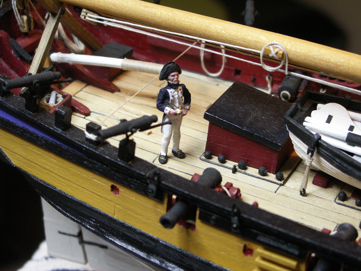
Jay, Thanks. He looks better than he did before I gave him the 'secret ingredient' and I hope, as you say, that he will dim down in time. I already have the mate painted, but that was with the 'old' paints, so he's fine. When it comes to the other three, as I said, I'll either try my technique – or buy new paints (I have a feeling the latter). Well actually, I'll be starting the new project during the summer, so it (hopefully) will be well before then. Floyd, I'm sure there'll be plenty to 'enjoy' at the cottage – including lawn mowing, painting, and laying a new floor in the bedroom. I just hope I get time for my new project! By 'fall', I guess you mean Autumn (for us European types) – which is very often the kind of weather that usually passes for 'summer'! Gregor, Glad you like the 'bosun'. As to your question, I think you must be referring to the 'vangs', that run from the gaff end to the quarters? I did research this somewhat, and had even put in belaying pins for them, before I discovered that cutters of this period didn't seem to have them. I was somewhat surprised, and they are not shown in the AOTS book on the Alert either. So, I now have a spare pin on each quarter, which I can either leave vacant, or perhaps use for something else. I am sure I will enjoy the summer, I just hope the weather plays ball! Thanks also for the new 'likes'.
-
Mike, Thanks, much appreciated. Well, the bosun didn't turn out too badly after all that, thank goodness. I just hope the others will be better, perhaps using different paint. Sounds like you'll be spoilt for choice between the Morgan or the Pegasus... decisions, decisions. I am sure whichever you do will be a credit to you. Thanks also, guys, for the 'likes'. At least it shows you're still following – even though the posts are few and far between! Actually this will be the last one for a few months, as the wife and I have moved out to our cottage for the summer, leaving Sherbourne back at home. I'll be returning to her probably at the end of September, or early October. Not to worry though, as I am hoping to start a new project whilst here. I won't say what it is just now, but I already have the plans... which gives the hint that it is the first tentative steps into the unknown...
-
Mike, Just catching up on your log, and I have to say that you're taking kit-bashing to a whole new level. You're going to such lengths to get it right, that I'd take my hat off to you – if I was wearing one, of course. I like the changes you're making, with the help of your new 'toys'. I reckon your next model will be a complete scratch build, right?
-
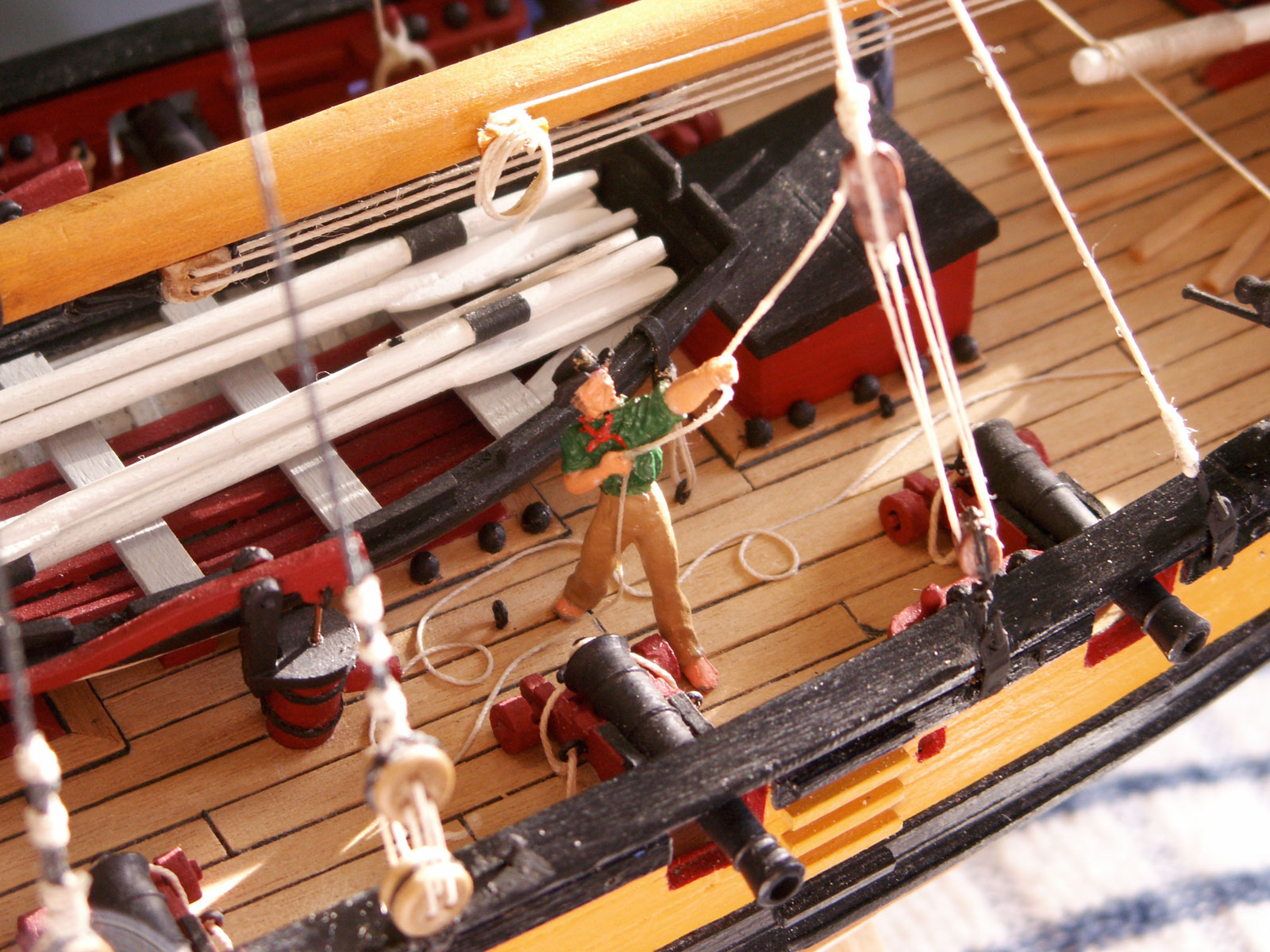
Before moving on to the yard strops, there were one or two problems to sort out. The crew figure mentioned in my last post (I’m calling him the bosun – since he has an official-looking hat, now with a badge) has been finished and positioned – and is in the act of hauling taught the fall of the larboard running backstay. This was left hanging in my last post. One problem I had here was in fixing the line to his hands, there being no slot or hole in them for the rope, which would certainly have made the operation a whole lot easier – manufacturers please take note! I therefore cut the line into three and attempted to glue the lengths in their respective positions whilst the figure was off the model. The line between the hands took quite easily, but unfortunately the other two (the one from the long-tackle block to the left hand, and that from the right hand to the deck) came away on moving him. I therefore decided to glue the figure to the model before attaching the latter two lines. However, the line from the LT block to his upper hand, which I had stiffened with glue, wouldn’t take, I think probably because I couldn’t keep my hand still sufficiently – and no, I hadn’t been drinking, or was suffering from caffein deficiency! I then hit on the idea of hanging a weighted length of thread and stiffening it with glue. When it was dry, and straight, I was then able to cut it to the right length, and glue it between the LT block and the hand. Then it only remained to glue the line from the right hand and realistically trail it along the deck. My other problem was with the acrylic paints that I had recently purchased (a neat set of 18 colours in 12ml tubes) with which to paint the four remaining figures, including the bosun. I had been under the impression that they would have dried to a matt finish, as had the bottled paints (now largely dried up) that I used previously for the lieutenant. Unfortunately, they dried to a semi-sheen – there being no indication of the type of finish on the box. On reading about acrylics however, I learnt that a matting agent is mixed with some types to dull them, and which had seemingly been mixed with the previous paint I had used. Luckily, I still had some of the older colours left, some of which I hadn’t used for some time, where the paint had separated and sunk to the bottom of the bottle. This had left a clear liquid on the top, which I reasoned was the matting agent, and it gave me an idea. I syphoned a little of this off into a small container, being careful not to include any residue of the paint – a dark brown(!) – which I then brushed over the painted figure. On drying, the paint was dulled somewhat but did not turn out quite flat, however I can live with it – just. It will probably be better to mix the liquid in with the paint for the remaining four figures or, if that doesn’t work, give the whole paint set to my wife who is something of an artist, and buy ones that dry to the desired, flat, look! Anyway, here’s the finished result: Following that somewhat windy digression, I’ll now return to the yard strops. The AOTS book on the Alert, shows that three of the four yards were hoisted from blocks seized to rope strops on the fore side of the mast. From the bottom, these were the spread yard, square sail yard, and topsail yard. The exception is the topgallant yard, its halliard running over a sheave set in the topgallant mast head and thence to the deck. The hoisting method for the three lower yards appears to have been the practice up until around the 1780's, when it was modified to reflect normal ship practice – and as seen in the arrangement for the latter yard. Since the Sherbourne is dated some fourteen years earlier than the Alert, she would almost certainly have had a similar system. At around the same date the whole masting and rigging of cutters underwent a revision. The lower mast and topmast became separate sections, with the topgallant becoming an extension of the topmast. The shrouds now passed around the actual lower masthead as per large ship practice, and the top mast was stepped forward of the lower mast, necessitating the introduction of topmast backstays. The three lower yards on the Alert/Sherbourne, were simply hoisted at their appropriate positions, at large single blocks suspended from strops, the halliards most likely being made fast at the foot of the mast (or at least that’s where I intend to belay them). It would seem that parrels weren’t used, apart perhaps from one on the topsail yard. It does seem an unlikely arrangement, and the wonder is that it lasted so long. The first strop and block above the backstays, is that for the spread yard. The strop I made of 0.50 mm black thread, with a 5mm block turned into one end and seized, as per the blocks for the backstays. This is the longest of the three strops and is set at what I thought an appropriate distance from its yard position. Next above that is the strop and block for the square sail yard. Again, 0.50mm black thread was used and a 5mm block was turned into its end and seized. Somewhat shorter than the strop for the spread yard, it too is set at a suitable position for its yard. The last strop and block over the masthead was that for the staysail halliard, and smaller diameter 0.25mm black thread and a 3mm block were used for this. Since the yards will not be rigged for a while, I decided to temporarily make the blocks fast to their appropriate mast cleats to prevent any movement. The staysail halliard I have belayed to the centre pin in the bitts in front of the mast: Next time: the staysail horse, and forestay.

-
Well, looks like I'm in the doghouse over this one. Woof! Eamonn, you're right, it was always called the 'doghouse' on yachts, and I have sailed on one or two as well – although I'd rather not say when. I'm not really sure what the structure was called on vessels of our period though. Anyone? How about Nigel's word 'enclosure', although that sounds as though it has no top... which could then get confused with the 'manger' on a lower gun deck... which I believe is where animals weren't kept... although not on cutters or schooners, 'cos they didn't have 'em... lower gun decks that is... if you see what I mean. I think I need a quick lie down. I think I'm with Nigel on this one, as I don't think you would be able to see much, just the top step if that. So, I'd save yourself a bit of work, and go with your instinct. As to 'brightening the place up', your Ballyhooligan is miles better than the kit already.
- 1,039 replies
-
- 2
-
-
- ballahoo
- caldercraft
- (and 2 more)
-
Eamonn, Is this something like you had in mind? I believe it's called a companionway, or doghouse (looks like a kennel?) perhaps. It has double doors on it's after side, both closed, and there is a thin strip across the top to represent a hinge. I had thought of having one door open but, as you say, you wouldn't be able to see much of any steps. I knocked it up from odd bits:

- 1,039 replies
-
- 6
-
-
- ballahoo
- caldercraft
- (and 2 more)
-
Jay, I'm with you now. You're idea of two boom supports, one to larboard the other to starboard, seems a strong possibility. The mainsail could be then lowered and the boom dropped into the most convenient crutch, depending on what tack the vessel had been on. This would also obviate the need, and perhaps difficulty, of centreing the boom. You're observations as to the differing length of the arms also makes sense. Jud, I'm not sure having the boom crutch to one side or the other would make much difference to stability, but from a practical point of view it would make sense.
-
Jay, Well, you have me confused now! However, at the present moment, I still think it's a boom crutch with the top orientated towards the viewer (as you suggest) for clarity. I can't imagine what else it would be, unless we go back to Welfack's suggestion of a support for the sweeps. If, as you say, this is mounted on the outside of the hull, then there should be another one – most likely further forward on the ship's side, but I don't remember one from the drawings. Is there one? Having sweeps mounted athwartships in this aft position wouldn't seem likely, as they must be about twenty feet long! They would also interfere with the boom – and I would have thought a few other things! Tony, I was going to suggest that the decorative tops actually form a lip, perhaps to be able to tie the boom (or whatever) down if required.
-
Tony, Mine came from ones I have seen used on older type wooden boats. I am sure there were different types. If you go with the one in your drawing, it will be interesting to see how it turns out.
-
Tony, I would think you are right. This looks to be a form of boom support or crutch, mounted centrally beneath the boom when the vessel is at anchor, to take its weight when the boom topping lift is eased off. It would probably be made of iron. I had thought about this problem when I made mine, and came up with a 'sheerlegs' type of support. Made of wood and hinged, they are designed to be unshipped when underway and stowed:
-
Anthony, Thanks for the link. I know of the book, although not read it. Quite an old book now, but still I think sound. Perhaps required reading for us cutter (and other) builders, for filling in the background?