


rlwhitt
-
Posts
158 -
Joined
-
Last visited
Content Type
Profiles
Forums
Gallery
Events
Posts posted by rlwhitt
-
-
Kevels and other Inboard Bits
Moving inboard to some of the items to finish here. There are 8 "Kevels", which are basically very large cleats for belaying ropes, attached to the stanchions. On the original Mayflower there were probably only these and railings themselves for securing various rigging ropes, as it would have predated the use of belaying pins. The kit comes with some pins as well since these exist on the Mayflower II replica. I suspect that they were used to make managing the ropes a bit easier for the modern sailors of 1957.
As for the Kevels, the kit is supplied with Britannia metal ones, and as with all such items are just so-so, and quite beg to be remade from wood as I have done here. Here is a picture of the metal exemplar, along with the scratch made ones in various stages.
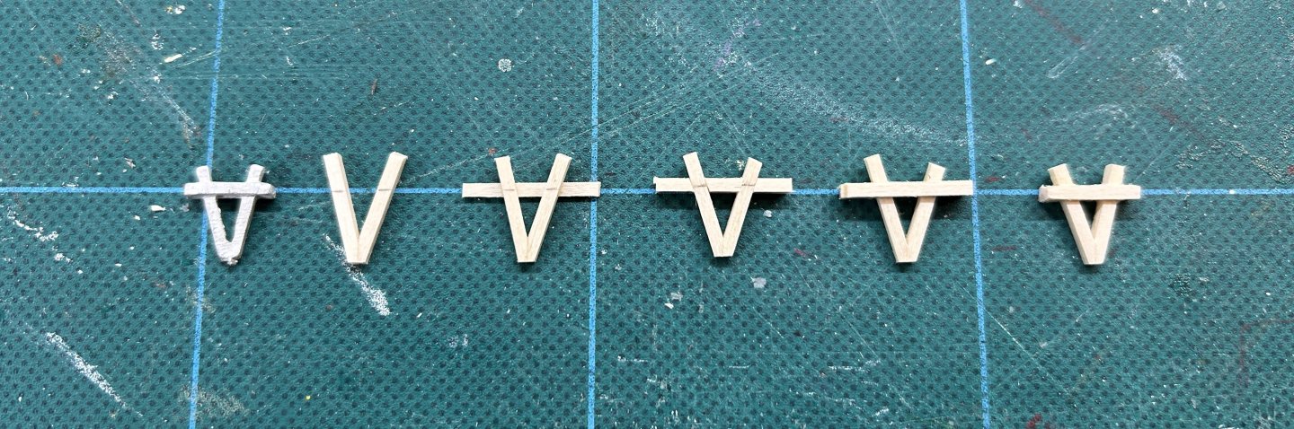
Left to right we have the metal one, then a simple "V" made from 1/16" square stock and marked at the point where the horizontal bar will go. Then the bar is made in layers, starting with a 1/32" x 1/16" strip on the back, with 1/16" square angle cut fillers, followed by another 1/32" thick strip. Finally, the ends are all trimmed and the overall thickness of the horizontal bar is reduced a bit.
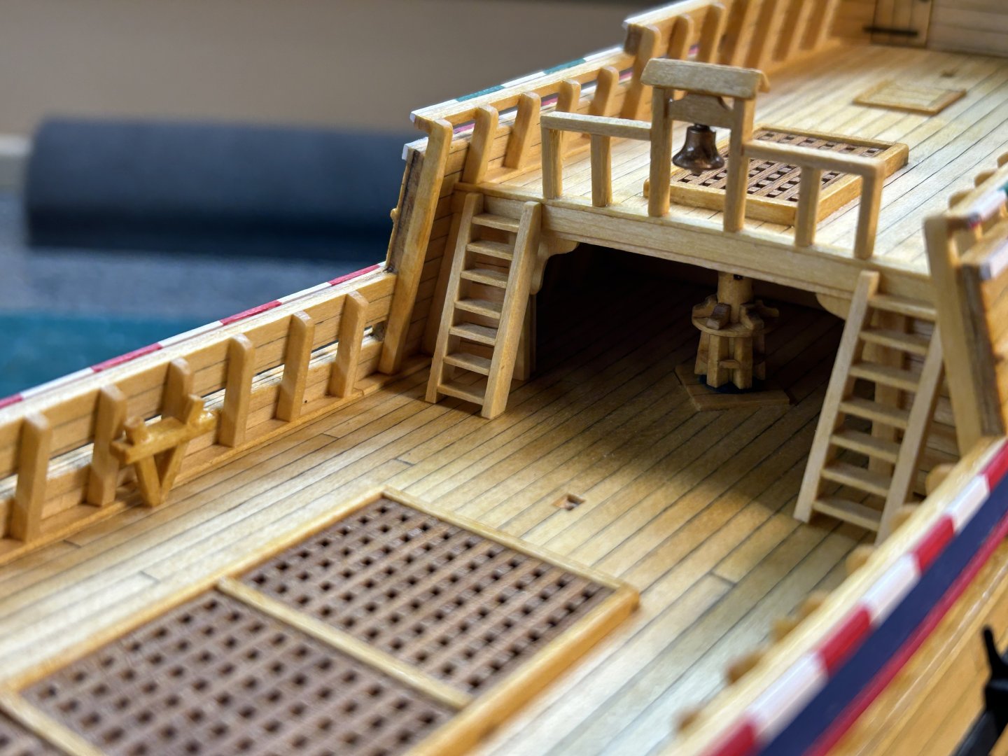
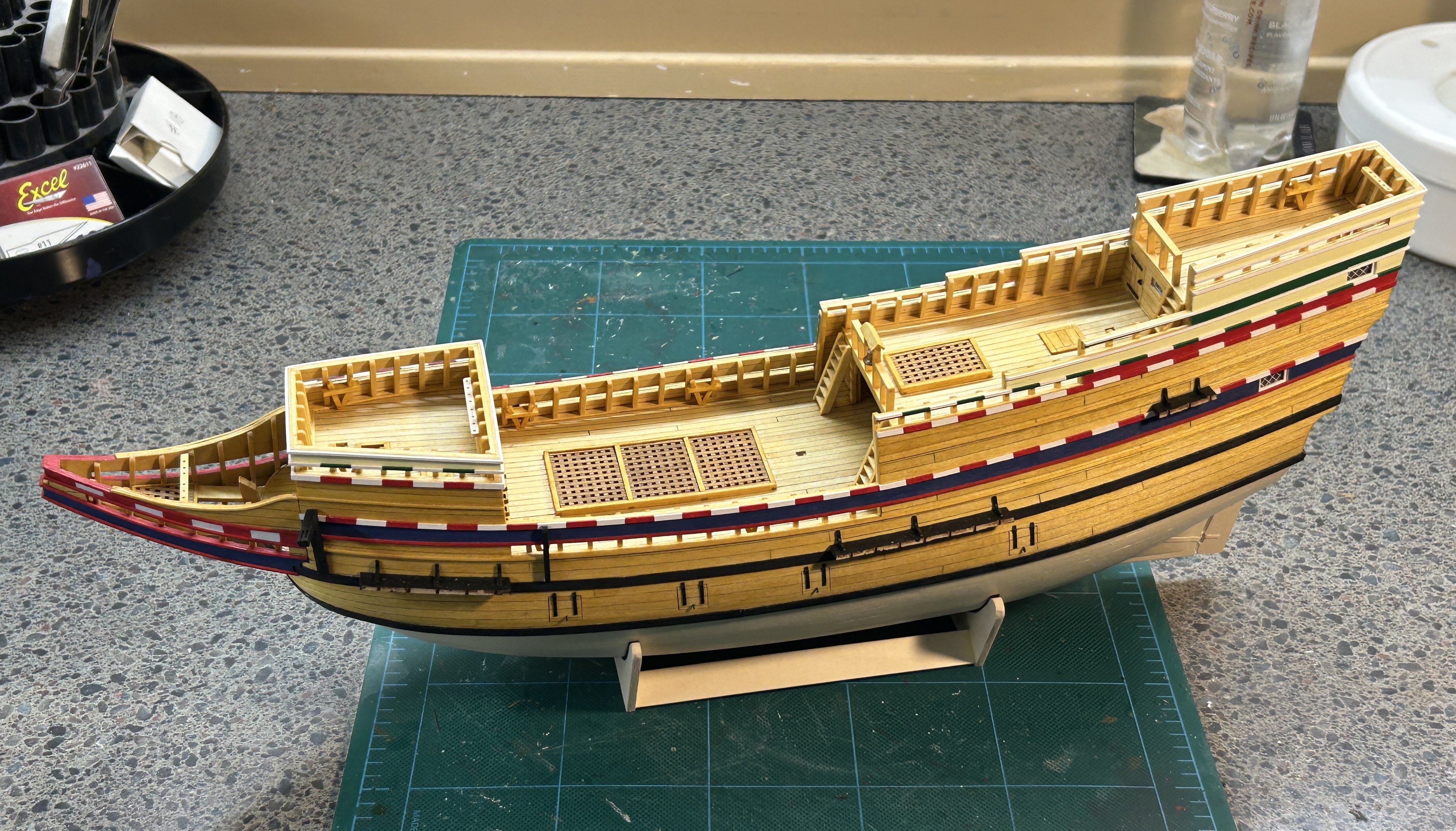
Here we have some shots of ladders, railings, belfry with a britannia metal bell, and some of the mounted kevels.

And an overall shot of the whole so far, on it's new stand.

-
Thanks Bob and Allan, and all the continuing views and likes!
-
That's truly a set of stunners B.E. Man that Indy is a beast, but also a beauty as well. I hope to do Sphinx one day but I don't think I'd ever have room for its big brother.
-
To Rig or Not to Rig
...that is the question. Actually, it's not normally much of a question for most people, for a subject like this. Hull only is usually seen only in later subjects where it makes more sense once the admiralty style of modelling became a thing. Not so much for models like this.
For that reason, I had originally intended to mast and rig this one, making it probably my only one that I'd fully rig. As I've alluded to in my prior build logs I don't like doing masts and rigging. Yes, odd choice of hobby for that predilection, huh?
") I've been dreading the job and have decided to be the oddball and make a hull only Mayflower. But so be it - I'm here to enjoy myself and dread the thought of the next few months of not enjoying the build - so I'll be stubbing the masts and bowsprit and calling it a day, moving on to more interesting projects (for me). I admire all you guys that enjoy and do so well with the rigging part, and I enjoy looking at them, just not the doing.
I've been dreading the job and have decided to be the oddball and make a hull only Mayflower. But so be it - I'm here to enjoy myself and dread the thought of the next few months of not enjoying the build - so I'll be stubbing the masts and bowsprit and calling it a day, moving on to more interesting projects (for me). I admire all you guys that enjoy and do so well with the rigging part, and I enjoy looking at them, just not the doing.
-
Display Stand
A brief diversion from the build...
Oddly, there's nothing provided in this kit for mounting, so you'll need to provide either a pedestal or cradle type mounting of your own. I prefer the latter, so I scratched one.
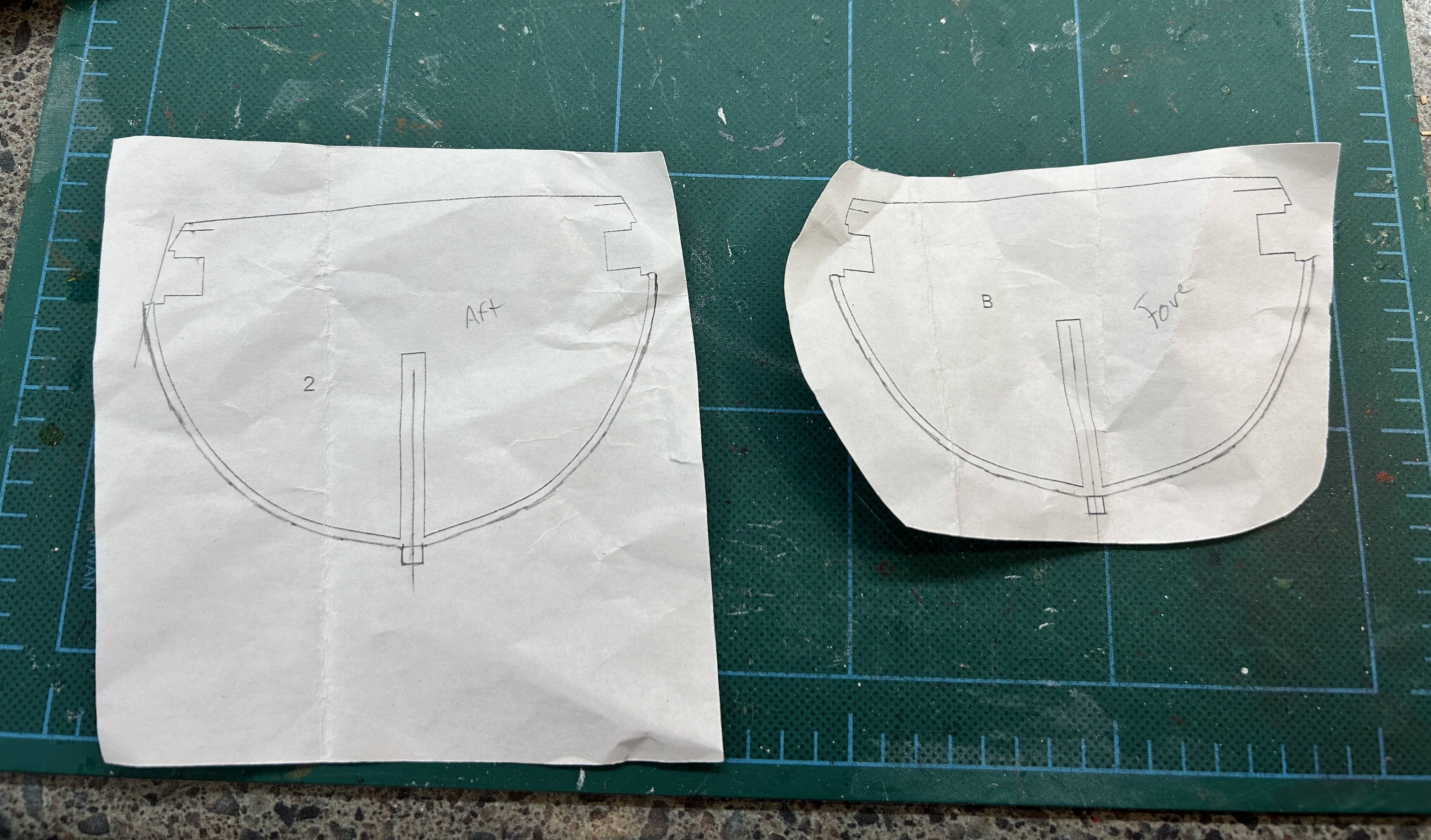
I started by picking 2 appropriately spaced bulkheads from the plans and cut out the part images, then traced a keel and planking line onto them to get a shape pretty close to the actual.
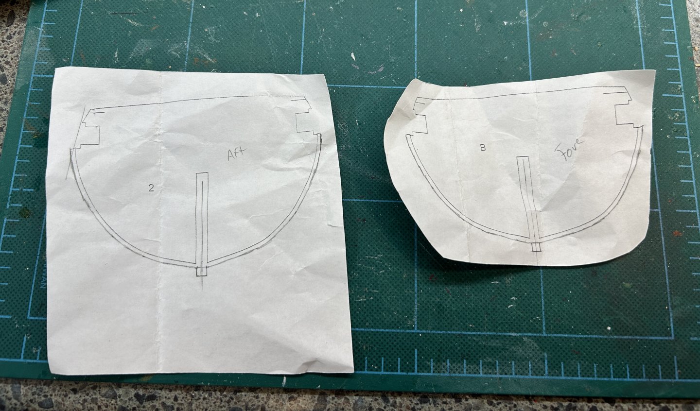
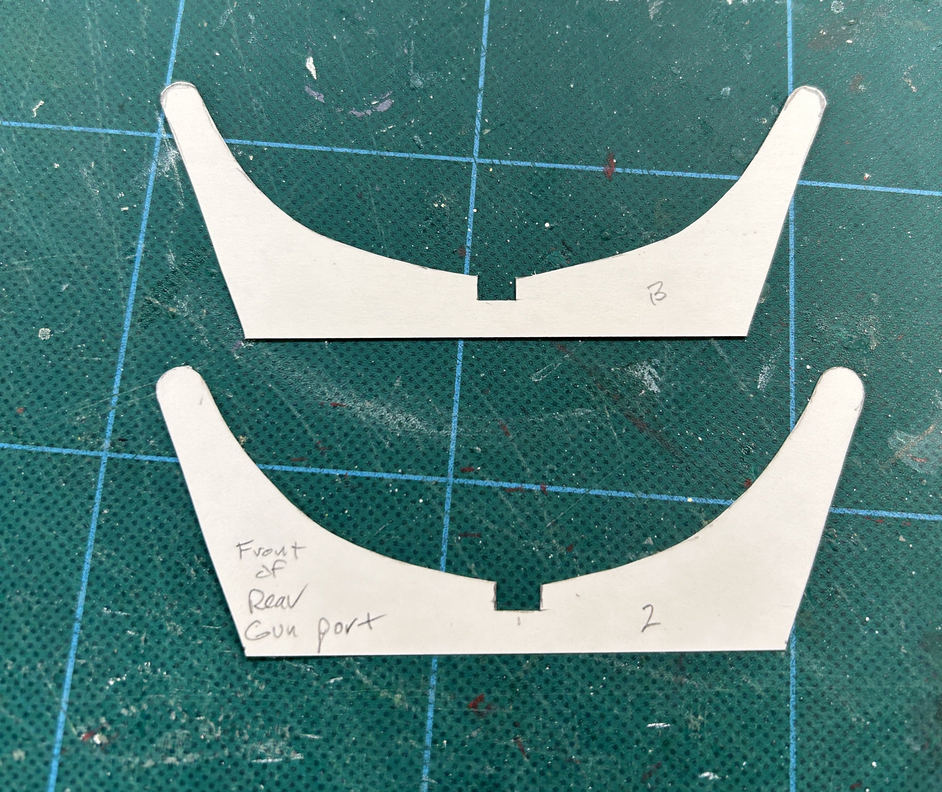
Then I cut that out and transferred the outline (with a little space to account for felt padding) to some card stock and then sort of came up with a reasonable shape for the rest of the cradle parts.
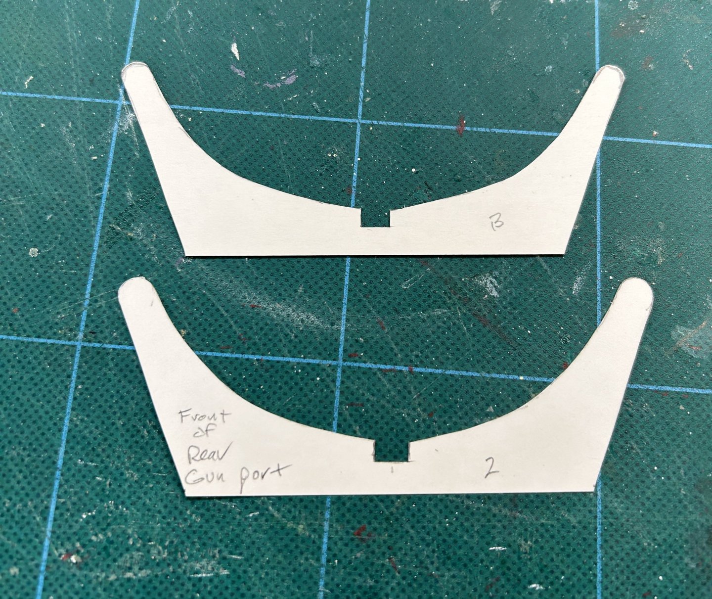
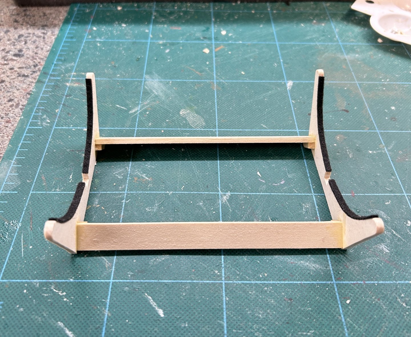
Then I used that to trace onto some 1/8" basswood sheet, cut them out along with some horizontal spacers and glued it all up. I've added some felt temporarily, which I'll remove when I get ready to finish/paint. The felt is some adhesive backed sheet I got at the craft store, 0.99 per sheet that'll last a long time! Cut, Peel and Stick - nice and easy.
Finished cradle:
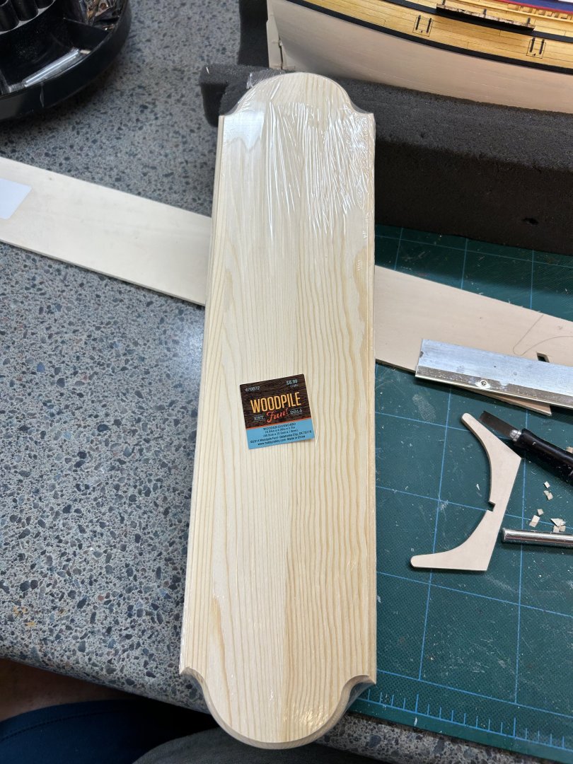
I'll probably mount that to a baseboard, and while I was at Hobby Lobby found that they have a nice selection of inexpensive pine craft boards, ready to use. This one was just the right size and was just $7! So if you don't feel the need for a fancier species of wood, this is a good source if you have one nearby.
-
Outboard Details
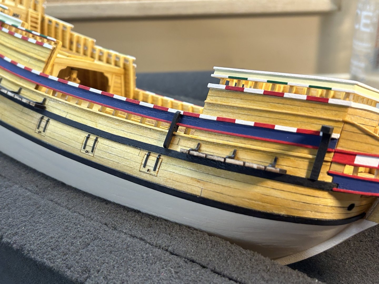
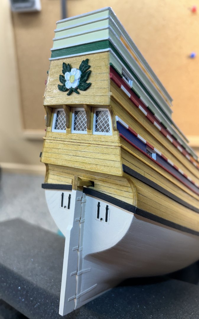
Finishing up some items on the outside, so that's basically done save for mounting the lower deadeyes to the channels and the anchors (last). Overall shots from the front and rear showing catheads, chesstrees, channels, port hinges, flower stern decor, and rudder/tiller arm.
One note about the rudder. The instructions call for the typical way of using brass strips and wire for the pintles and gudgeons, but I have been going against that grain on mine and use thick card stock and tiny dowels instead. I find this much easier to work with. If it's painted there's not really a difference in appearance.
Another thing to note that the instructions mention using the plans to cut things like cathead and chesstree pieces from stock. They are in fact provided laser cut, though oddly only one cathead part! Luckily there is plenty of extra stock on that sheet to trace and cut another one.
A word about port lid straps/hinges. I cut thin strips of card stock and glued them to some medium sized black rigging rope with CA to form a "hinge pin", and then used some slightly open tweezers to press fit the card stock down around the rope to make the hinge profile shape. Finally I cut the rope almost flush to the edge of the strips. I did this in groups of 4 on one length of rope to get consistent length and placement. I wish I had taken pics of this process. Once cut, I CA'd the strip with the "hinge" on the back at the top of the port lid. Since it's all painted black it looks pretty decent at this scale.
- chris watton, oakheart, Thukydides and 1 other
-
 4
4
-
Another outstanding masterpiece in distilled wood!
-
Gorgeous planking! If I could plank that good I'd be loathe to cover it in paint or copper.
-
-
This is truly master class stuff here. I'm at once inspired and humbled when I see things like this. Just WOW!
- Keith Black, mtaylor and cotrecerf
-
3
-
11 hours ago, kirill4 said:
Good day,
Dear Rick,
Very clean ,precision and accurate job done!
Those "access" boards shown on the beackhead, are they kit's idea?
Looks quite unusual, as far as I knew, there used to be a full grating deck, often shown in special form of long strips with wide opened cells ( as I understood for easy passing water in/out in rough seas) instead of shape of gratings which used on decks, for these may be sence to fabricate them from scratch?
and there used to be placed a couple of crew's "seats of ease" , in the corners... ?
All the best!
Kirill
Some pctrs of Willem Barents replica ship , constructions mentioned above
Yep, just following the instructions on this part. It actually described a sailor going from the doors out to the grating.
-
Oh those kinds of bits are the worst! Even more than radial engine cylinders.
- mtaylor, Egilman, Keith Black and 4 others
-
7
-
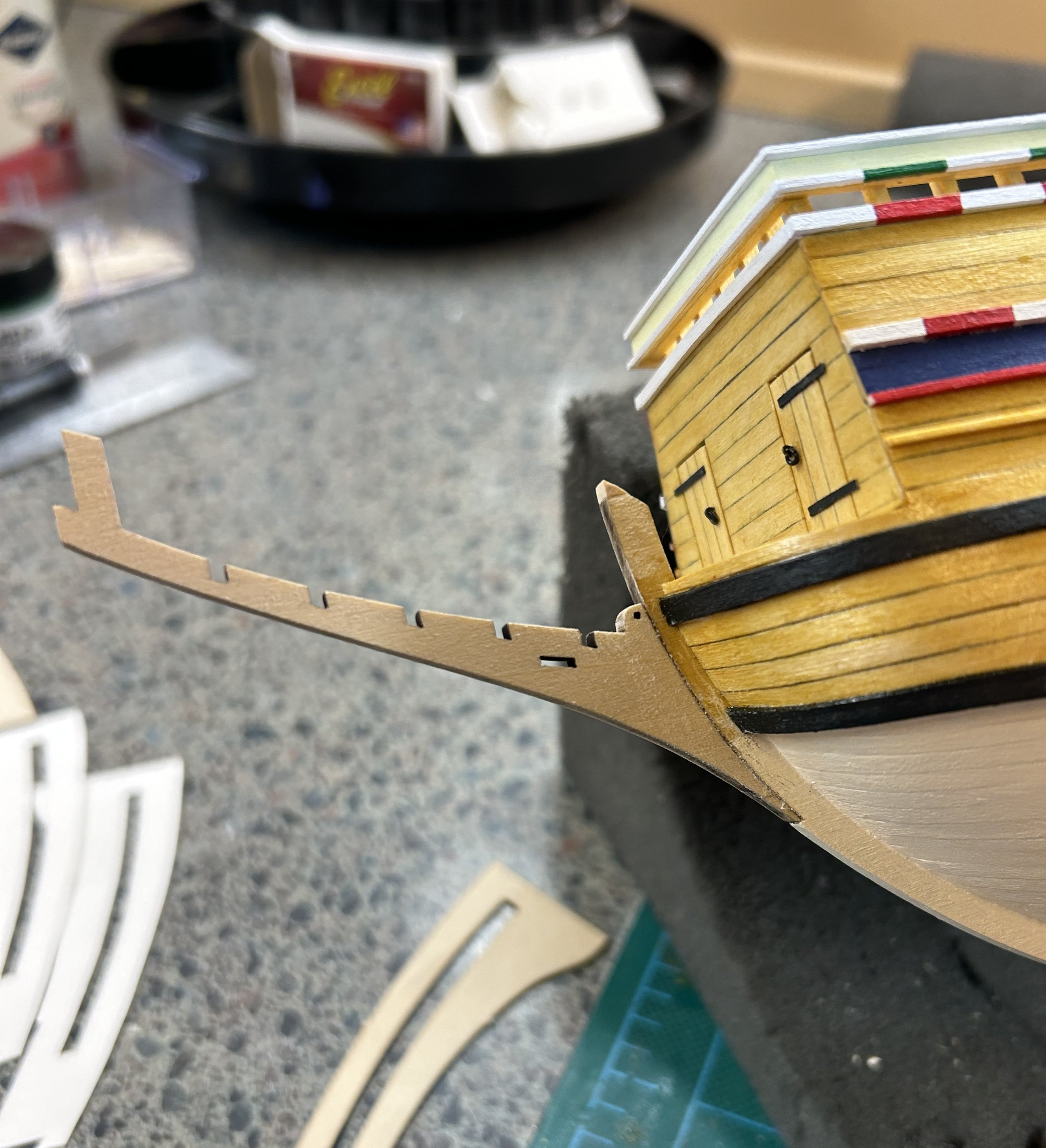
Beakhead
This part is quite the project all by itself - there’s a lot to do here. First we glue on the stem knee:

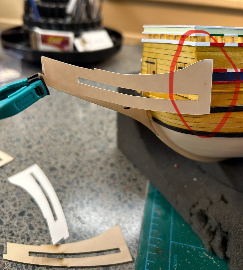
Next we add the sides. These are laser cut 1/32” thin parts that are planked. Before planking they need to be cut to the right size and precise shape. They are provided quite oversized to account for differences in your build. As recommended I made card stock tracings and first cut those down basically to size. You can see from the circled part of this pic how much extra is provided. I actually ended up cutting only enough off the back end to make the angle right, and cutting most of the length from the front end. Then use the card patterns to make cuts to the wood part.
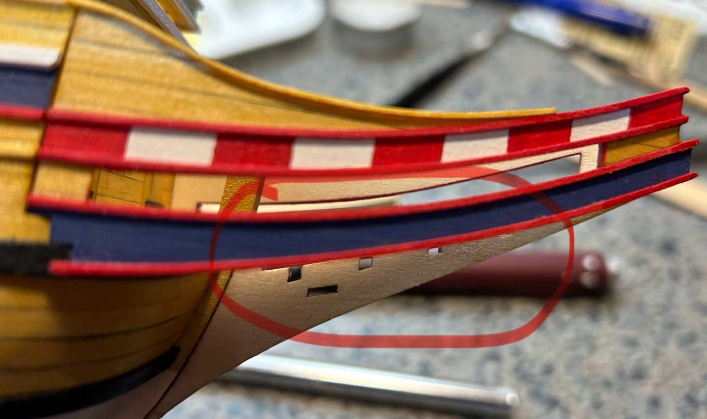
Then comes planking the outsides and starting some base paint. Here you can also see the beginnings of notches to fit around the beak head deck and upper wale:

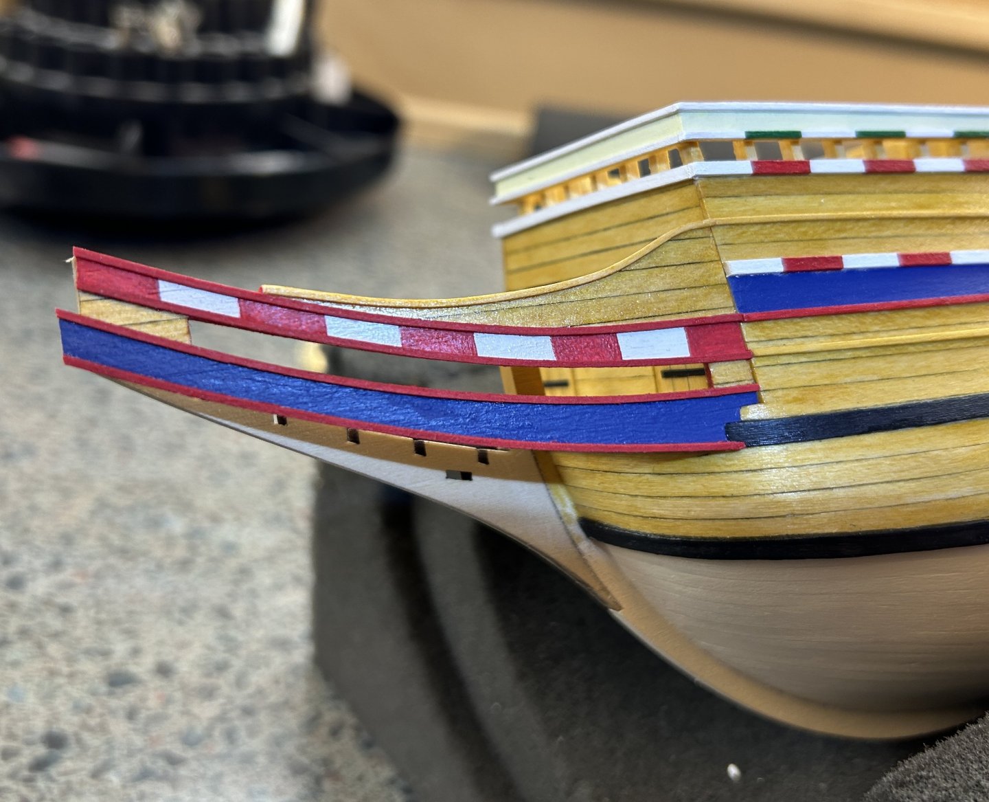
Here is one side with finished paint and moldings, glued on
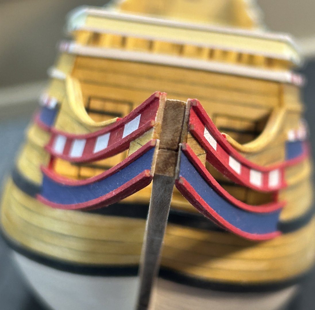
At the front, some scrap bits and moldings will be needed to finish things off:

Next we need floor timbers, which span between the sides at the bottom, and are designed to slot into the stem knee. However as illustrated by the circles on my build pic, the slots are too low for most. So I just ended up inserting some filler to bring the bottom of the slots up
view at the bottom with the floor parts in place, including some knees and side strips:
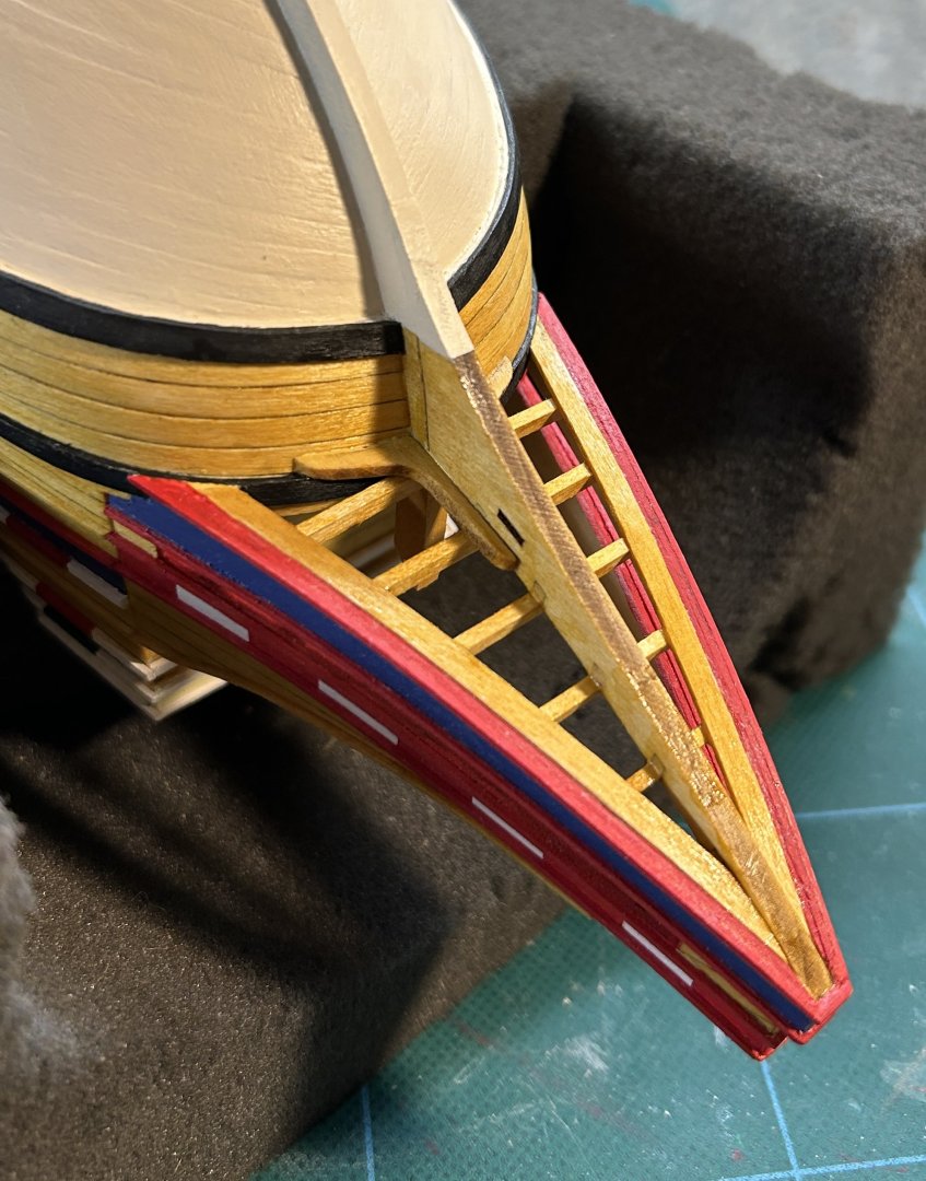
And finally, a view up top with all the stanchions in place, plus a grating, access boards, and a pin rail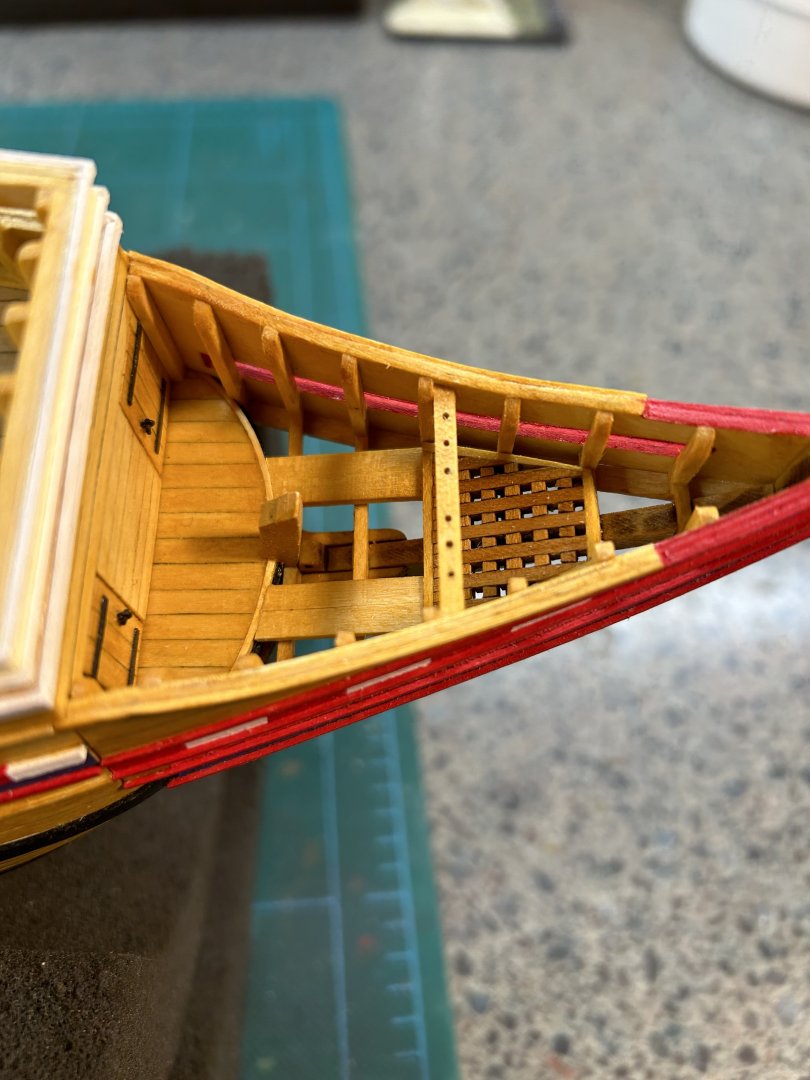
-
Great finish Bob! She’s going to look great in that case.
- Keith Black, Glen McGuire, Knocklouder and 1 other
-
3
-
 1
1
-
Hi mugje, in regards to the Amati (actually, is it the Art Lat one?) plank bender - I've seen it an often assumed it might make crimp marks even on the outside of the plank. Looking at your results it certainly doesn't seem so - or have you sanded them out? How thick a plank can you bend with it?
Thanks and looking good!
-
Thanks Bob, Dave and Chuck, and all the Likes along the way. Your encouragement is much appreciated!
- Baker and Scottish Guy
-
2
-
-
Thanks guys!
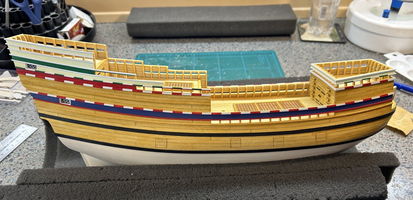
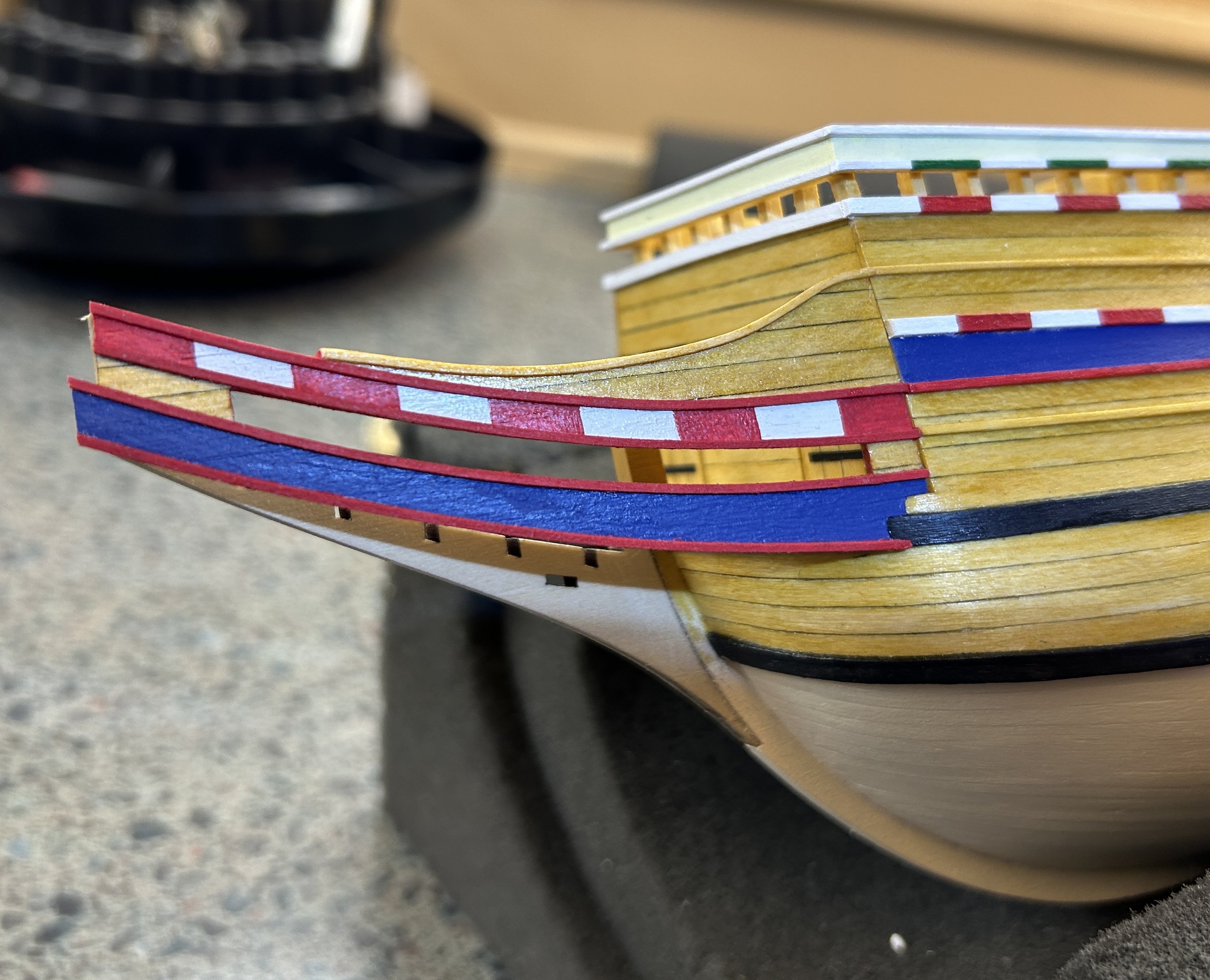
One comment about paint colors. As I started sifting through all the pics online of this ship one thing is obvious. It has had many color schemes over the years. I think every time it needed a refresh or renovation, they've changed it up some. Right now the entire ship is painted some kind of yellow occre shade with generally muted panels (brown, etc) between some of the moldings. In the past most of the outer planking was left natural/stained more like I have it here. And the waterline treatment has been several different configurations as well. I've mostly followed the instructions colors which is supposed to be close to the 1956 launch scheme, with the exception of the blue panel under the main rail, which I think looks better. That was done later though not precisely the same shade.
As others have said, in real life Mayflower was an unremarkable merchant ship and most likely would not have shown any fancy colors at all, so all this is probably just sort of artificial glitz to make it look interesting.
- Knocklouder, Scottish Guy, mugje and 1 other
-
4
-
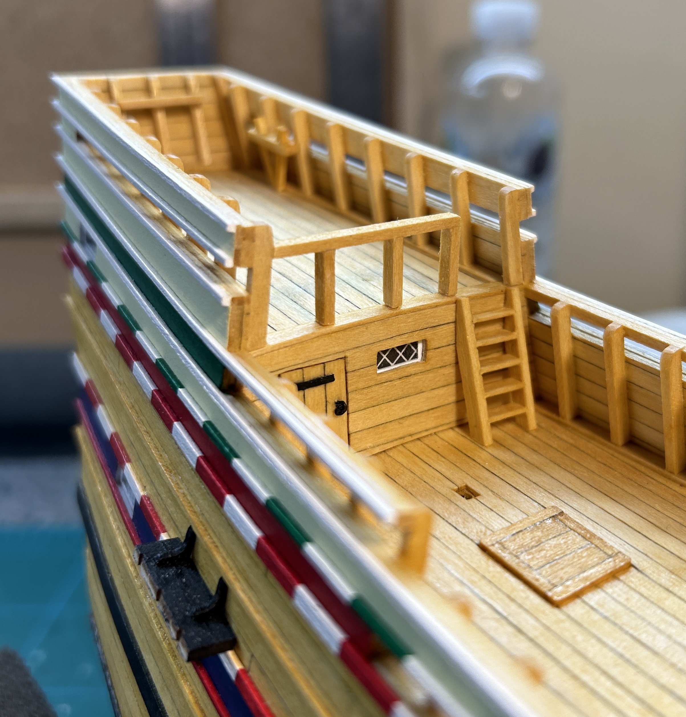
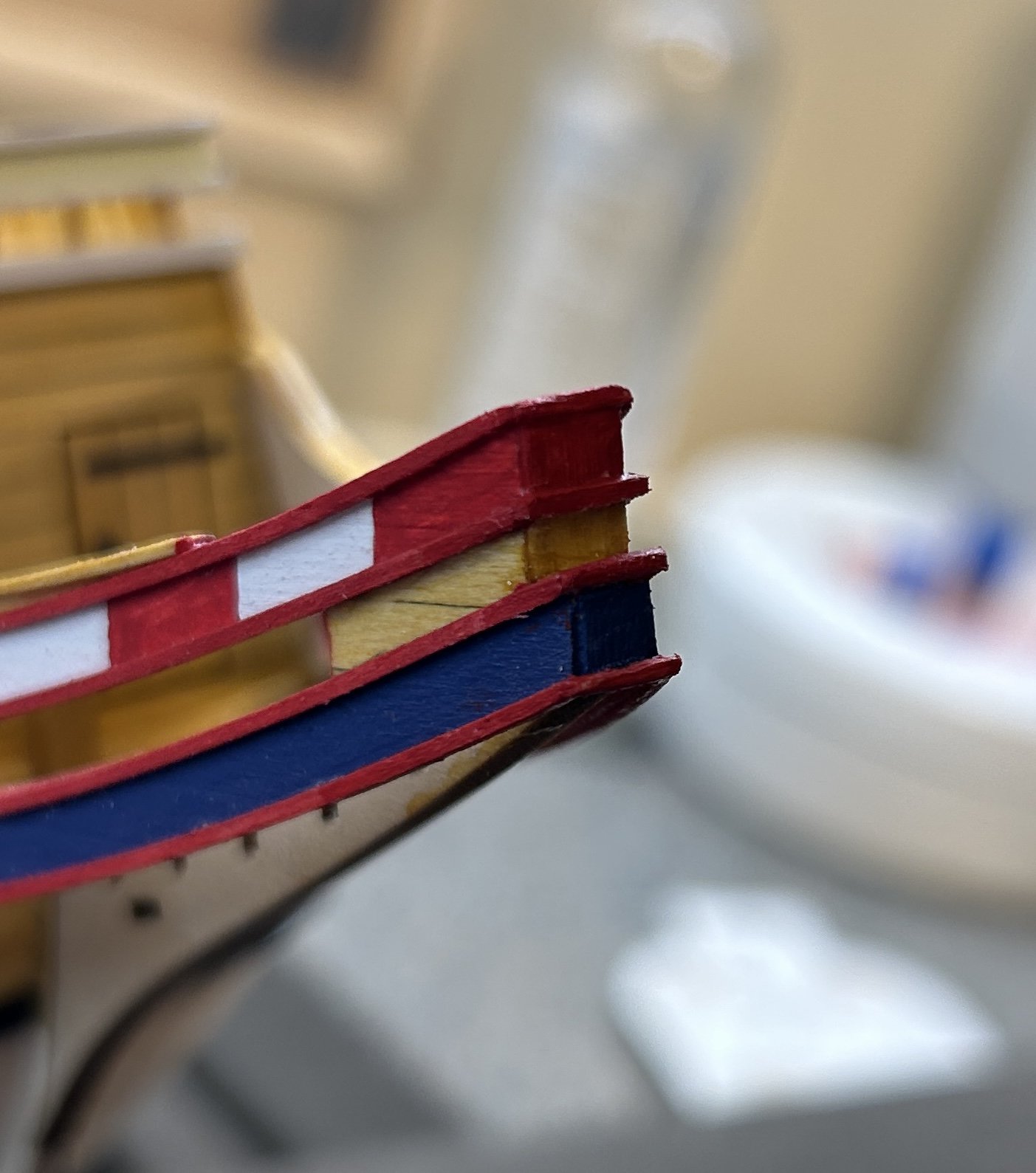
Molding Strips and Painting
Tedious step here, painting and applying all the various strips, with stripes on some. It’s tricky trying to get them aligned and even and I have not gotten it 100‰ right. One issue IMO is that the upper window seems to be just a tad high, forcing the strips that border the top and bottom of it to be also a bit too high. I’d suggest anyone building it to consider lowering it a bit, maybe 1/16” or so. But overall I’m satisfied with the way it’s turned out.
-
29 minutes ago, LCdr Dave said:
Not to hijack your post, but I’m having a hard time figuring out where the rigging goes in some cases. I also seem to have parts (or lack parts) compared to others. If you don’t mind I might be able to message you separately and you may have some insight.
cheers,Dave
Well since we are working on kits from different brands and there are quite a few differences there might not be much help to be had, but maybe in the rigging plans I have there could be something.
-
Thanks Dave! What kind of issues are you running into?
-
-
-
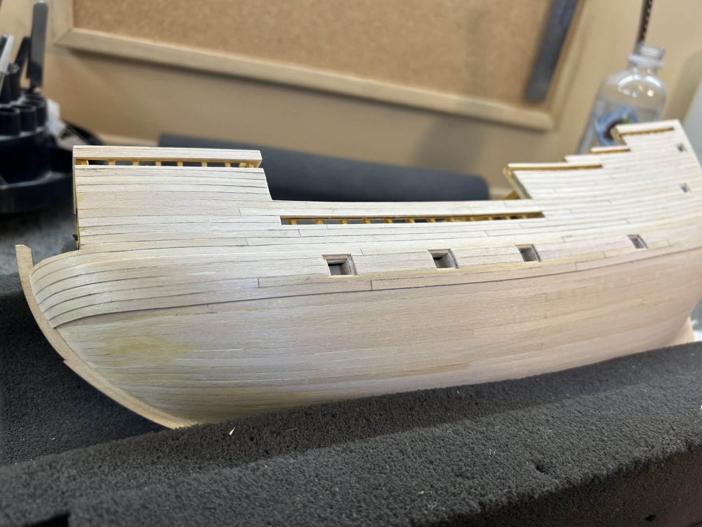
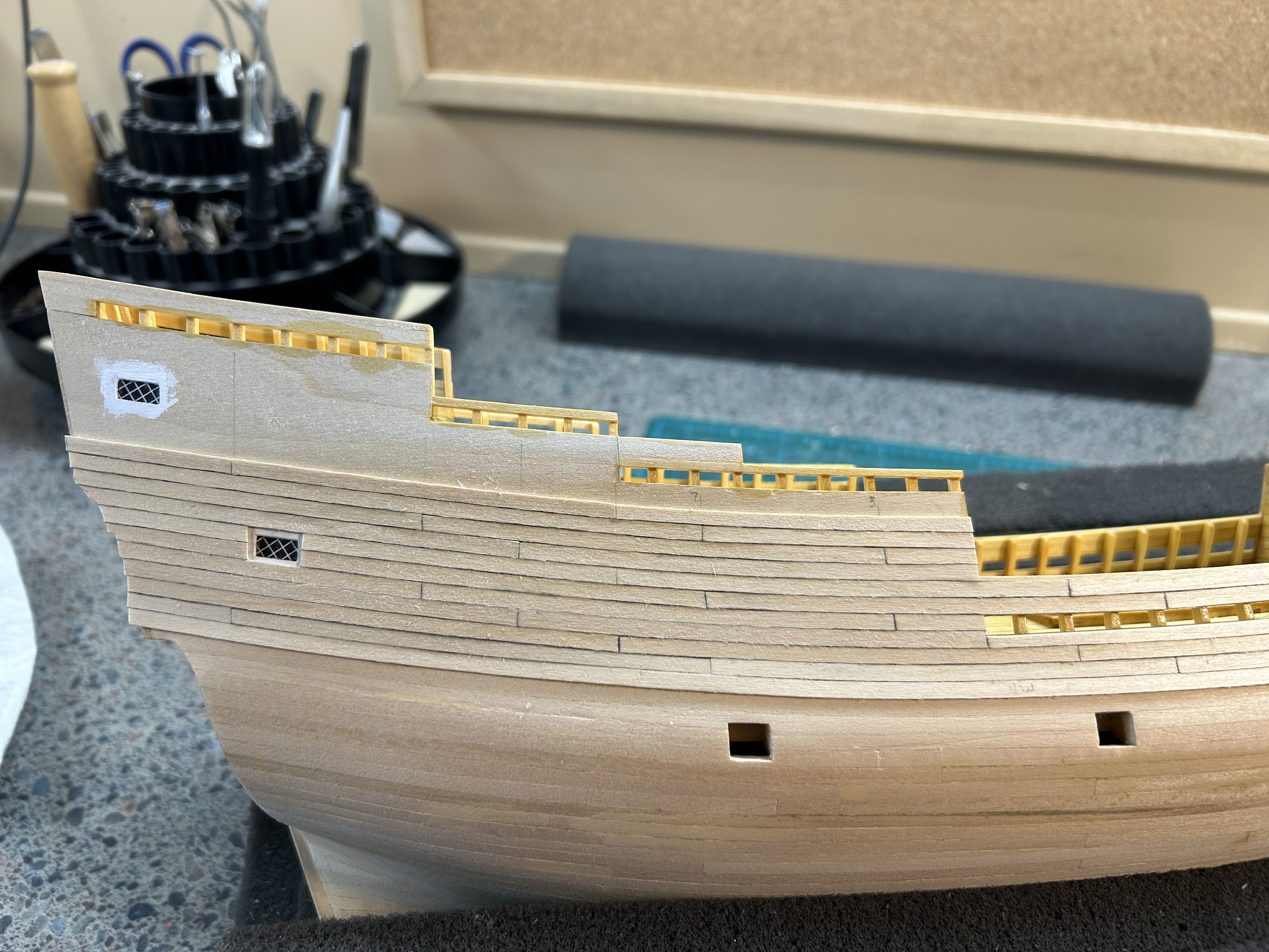
Outer planking, Gun port lids, Wales
Now it's time to move outboard and get all the hull planking done. The first thing to do is to make a starter plank with the top edge aligned exactly with the bottom of the bulwark template. This is a very important step as all the rest of the planking's correct positioning depends on it.
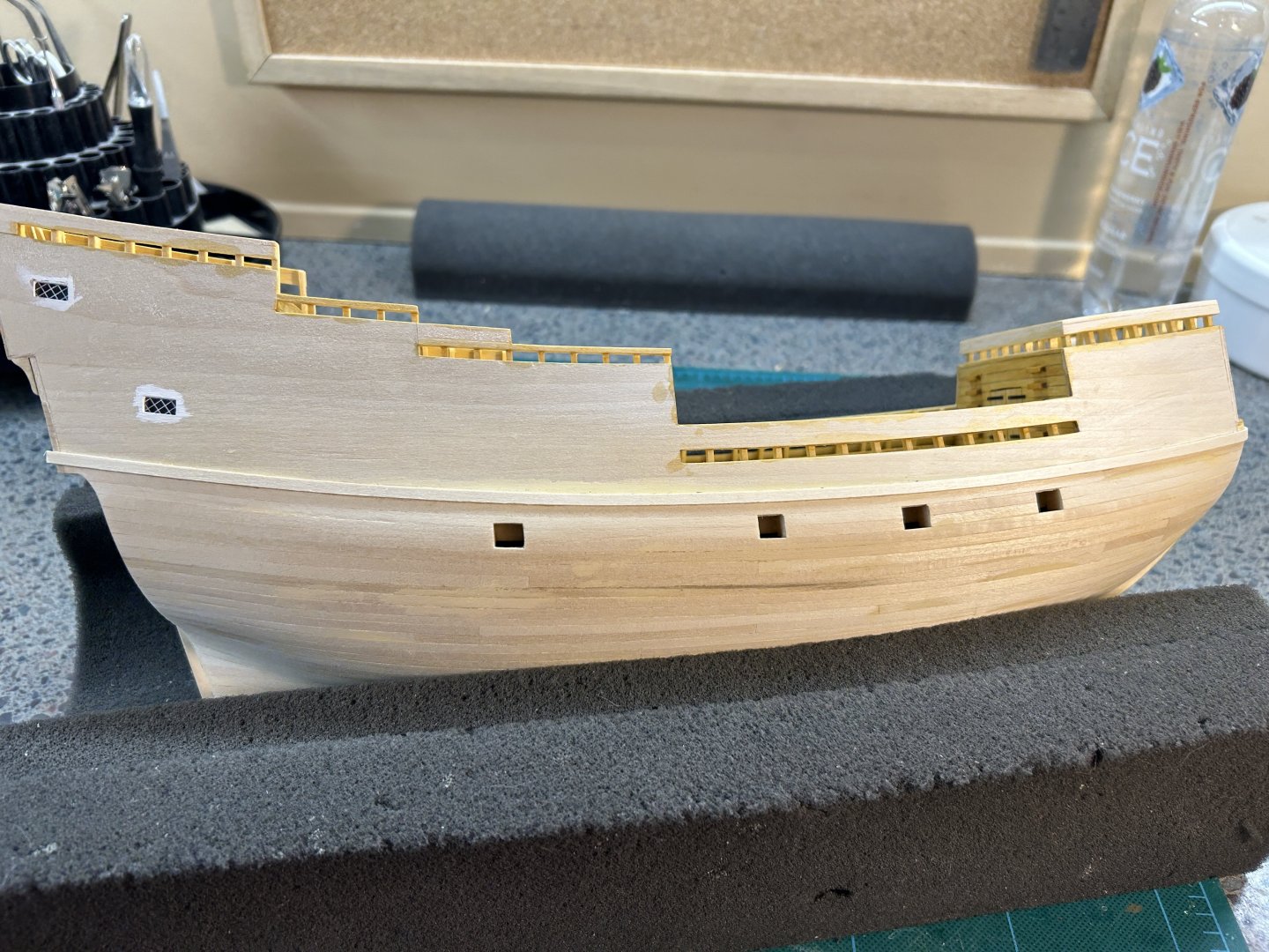
From there we start planking up the sides. Here you can barely see some pencil marks I made on the bulwark templates to indicate where to put the planking joins:

One side upper planking complete, before final sanding:

The bottom strake of the upper planking (the first plank you put on), will become the upper wale. The wales in this case are nothing more than another 1/32" x 1/8" strip just like the rest of the planking, so the wales are just doubled planks.
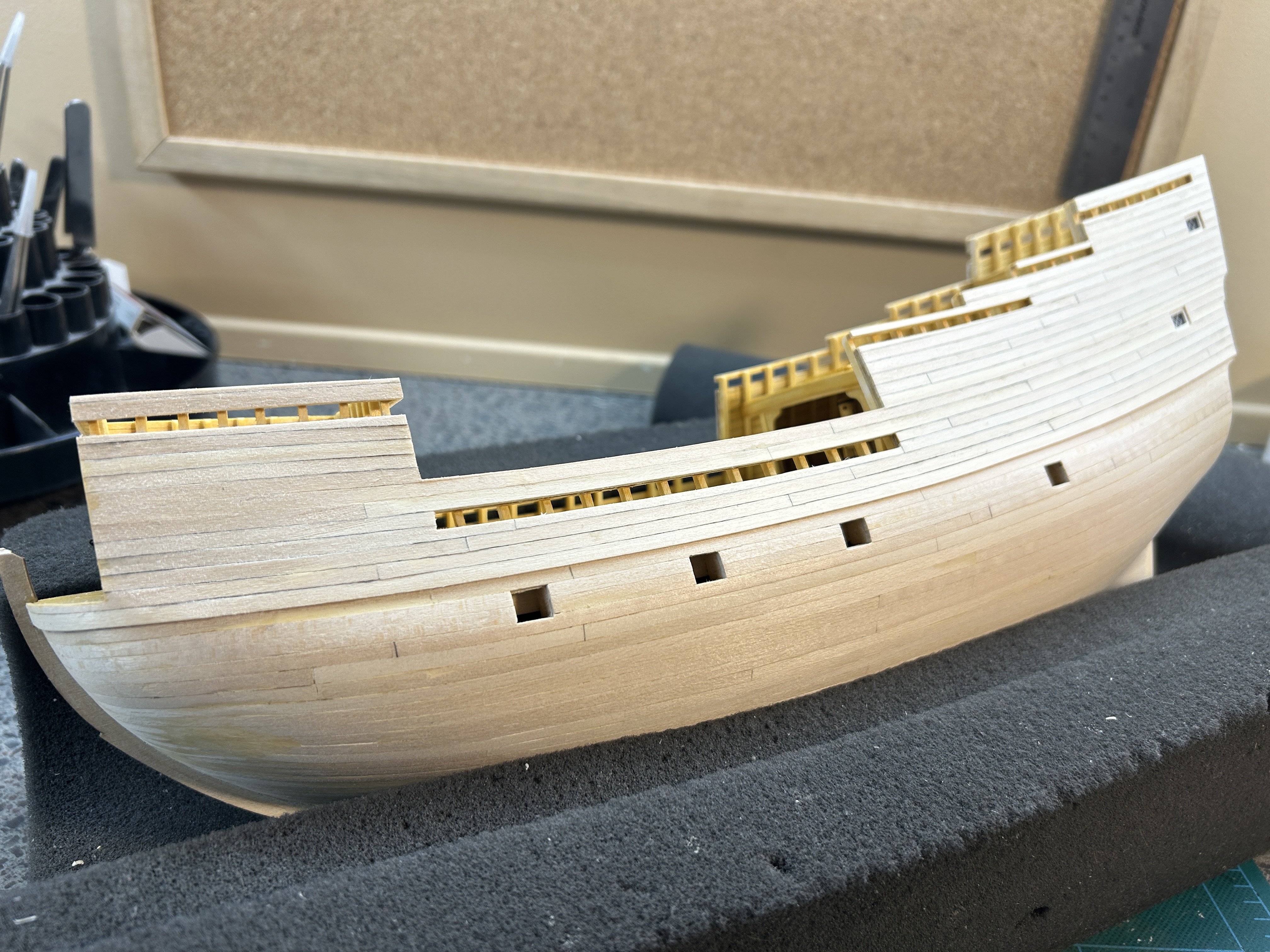
Next we add 5 strakes below the upper wale. The bottom strake of that set will be doubled to become the lower wale. Here we have that done, with margins left around the gun ports:
OK, now comes a key choice in the build. The 2nd layer of planking below the main wale is not technically required, so you are given a choice. Supposedly there is enough of the 1/32" planking to do the rest of the hull down to the keel, but not in my case - there's not enough even if I wanted to do it. Maybe I was a bit wasteful in its use so far but I really don't think so. Everything below the wale will be painted so small imperfections can be filled/sanded. So if you are content with the shape of things down here, no real need for the 2nd layer. Mine's not perfect, but I don't think I'd improve things much or at all with a second layer, so mine's going to the paint shop as-is.
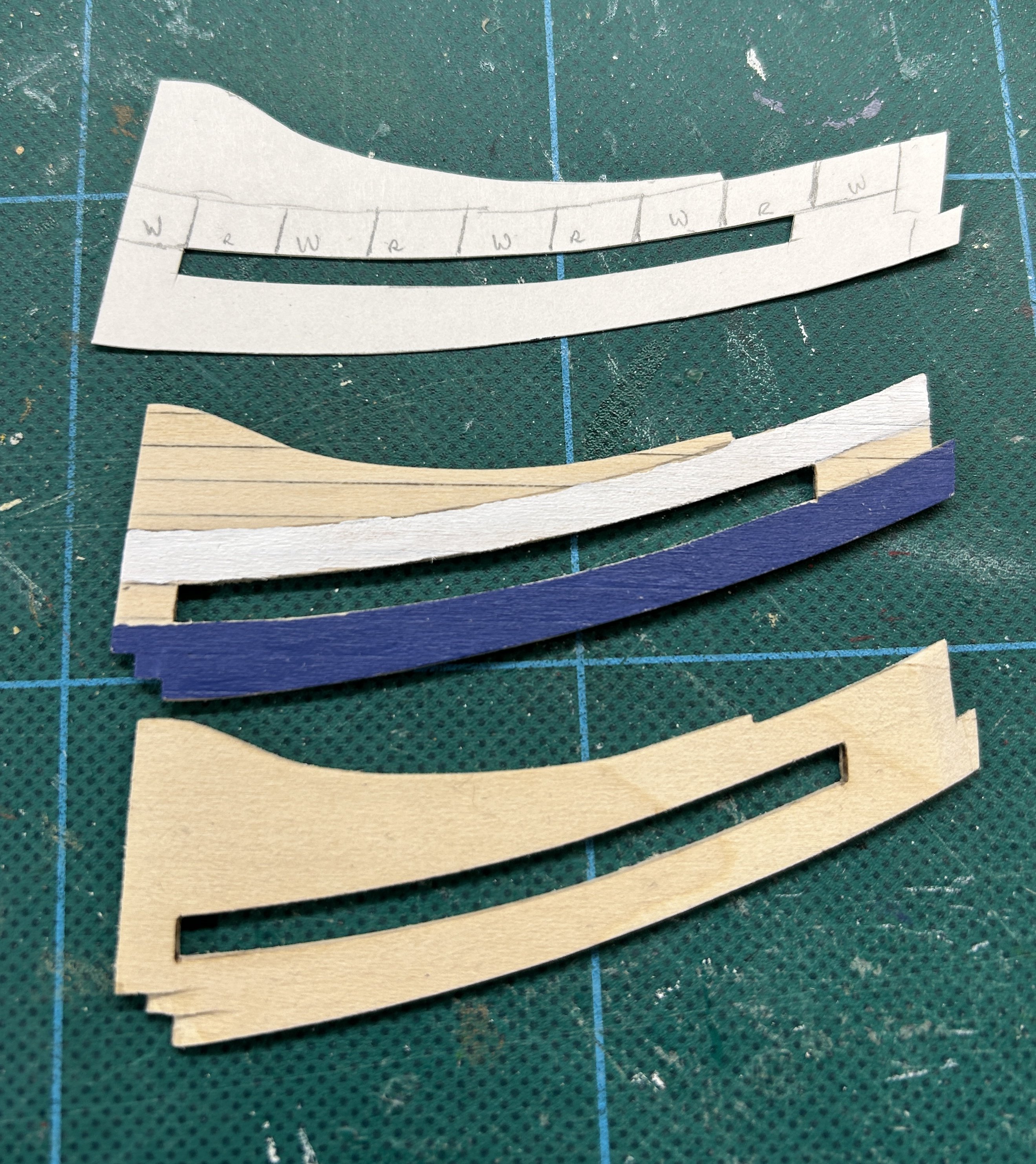
How you treat the gun ports is another choice. You can put in the dummy cannon barrel tips and show the lids open, or you can show them closed. My choice is closed, since I don't think in real life you would have typically seen a common merchant ship like this with guns run out. I believe the real Mayflower would have actually carry them stowed, "just in case" (Pirates!). Someone who's seen it in person correct me if I'm wrong but I don't think Mayflower II ever had them, except for maybe 1 sample one at the stern, just going by the pictures online.
Anyway, mine are going to be done closed. I started by making some blanks out of 4 planks penciled and glued up like the example below. Then I cut port lids out of it trying to align the plank joints as best as the inconstant width planking supplied would allow.

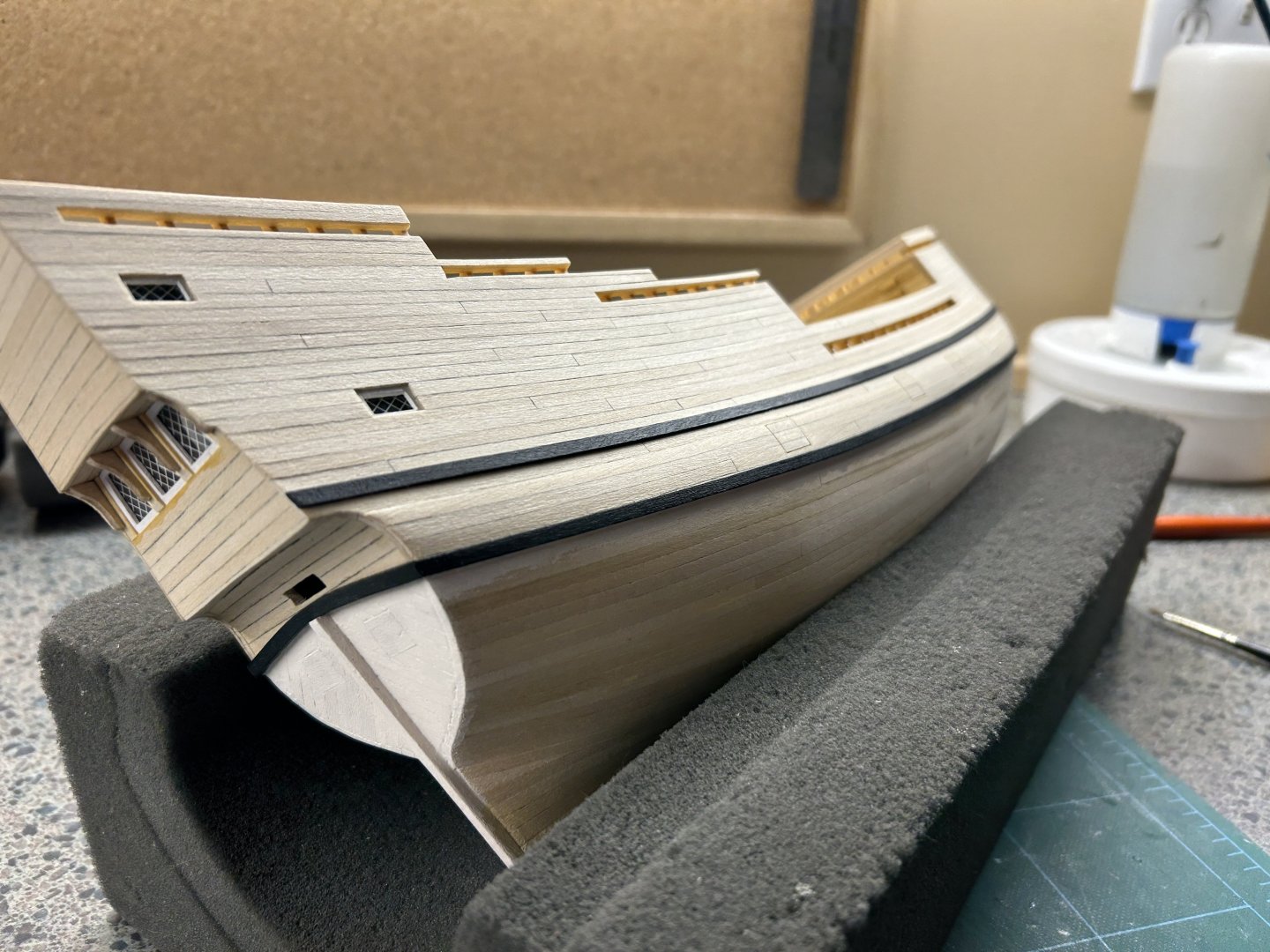
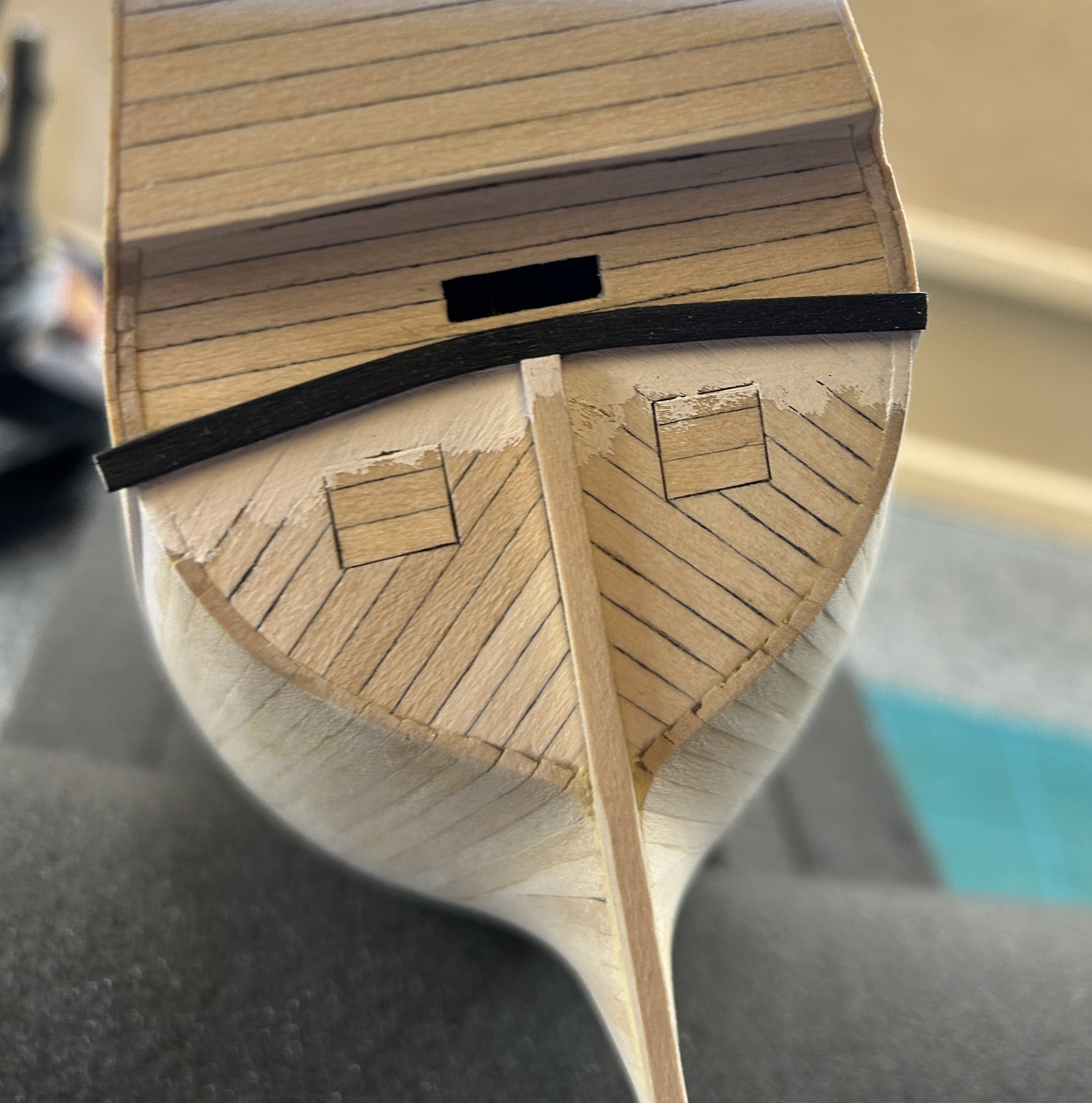
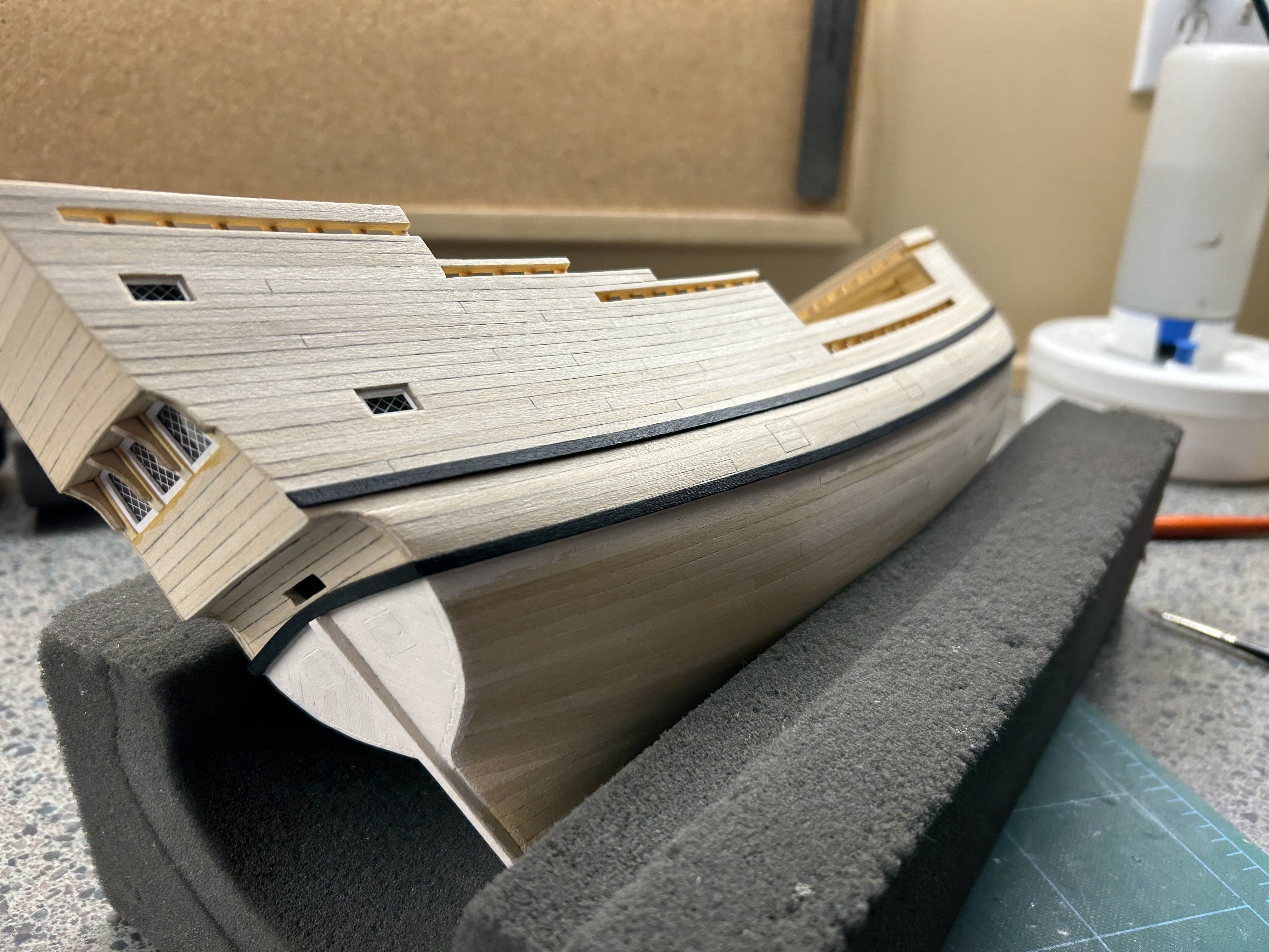
Moving for a moment to the back, I went ahead and did the stern part of the main (lower) wale. Not much is said about this in the manual, the pictures there show it pretty much straight across and intersecting the stern post somewhat. Looking at pics of the real thing, it's got quite a pronounced curve, like I've done here. I used the thicker 1/16" planking stock instead of the thin stuff and used the edge bending jig to get the curve:

Finally, here we have both wales on this side complete. Next up will be the decorative trim strips and bunch of painting.


Mayflower 1620 by rlwhitt - Model Shipways - 1:76
in - Kit build logs for subjects built from 1501 - 1750
Posted
Thanks Allan! The kit provides grating strip material (sawtooth looking stuff) that you cut into measured pieces and then interlock together.