Javelin
-
Posts
638 -
Joined
-
Last visited
2 Followers


Recent Profile Visitors
3,544 profile views


-
 Javelin reacted to a post in a topic:
Christiania 1774 by TJM – approx. 1:67-1:64 – Danish Light Frigate based on Vanguard Models HMS Sphinx
Javelin reacted to a post in a topic:
Christiania 1774 by TJM – approx. 1:67-1:64 – Danish Light Frigate based on Vanguard Models HMS Sphinx
-
 Paul Le Wol reacted to a post in a topic:
Columbia 1835 by Glen McGuire - 1/400 - BOTTLE - Steam Packet
Paul Le Wol reacted to a post in a topic:
Columbia 1835 by Glen McGuire - 1/400 - BOTTLE - Steam Packet
-
Canute reacted to a post in a topic:
Columbia 1835 by Glen McGuire - 1/400 - BOTTLE - Steam Packet
-
 Glen McGuire reacted to a post in a topic:
Columbia 1835 by Glen McGuire - 1/400 - BOTTLE - Steam Packet
Glen McGuire reacted to a post in a topic:
Columbia 1835 by Glen McGuire - 1/400 - BOTTLE - Steam Packet
-
FreekS reacted to a post in a topic:
Chaconia by Javelin - 1/100 - RADIO - LPG Tanker
-
Keith Black reacted to a post in a topic:
Columbia 1835 by Glen McGuire - 1/400 - BOTTLE - Steam Packet
-
Dr PR reacted to a post in a topic:
Chaconia by Javelin - 1/100 - RADIO - LPG Tanker
-
Dr PR reacted to a post in a topic:
Chaconia by Javelin - 1/100 - RADIO - LPG Tanker
-
 Pretty sure you've tackled worse challenges.... I remember watching the movies of you other famous PIB (paddlewheeler in bottle). The only other way to solve this issue that I can think of, would be to drill a hole in the funnel, connect the stays to the ship, insert the ship with long rope ends staying outside of the bottle. Then slide the funnel over the ropes to its position. Once glued, you tighten the ropes and cut off the long ends close to the funnel. This is a technique I used on the Scheldt River build. I do believe you chose the easier option 😄 In any case, marvellous paddles. Love the way you did that text on the sides. I don't think my printer would manage something that small.
 -
Rik Thistle reacted to a post in a topic:
Chaconia by Javelin - 1/100 - RADIO - LPG Tanker
-
Paul Le Wol reacted to a post in a topic:
Chaconia by Javelin - 1/100 - RADIO - LPG Tanker
-
Javelin reacted to a post in a topic:
HMS Bellona 1760 by SJSoane - Scale 1:64 - English 74-gun - as designed
-
Keith Black reacted to a post in a topic:
Chaconia by Javelin - 1/100 - RADIO - LPG Tanker
-
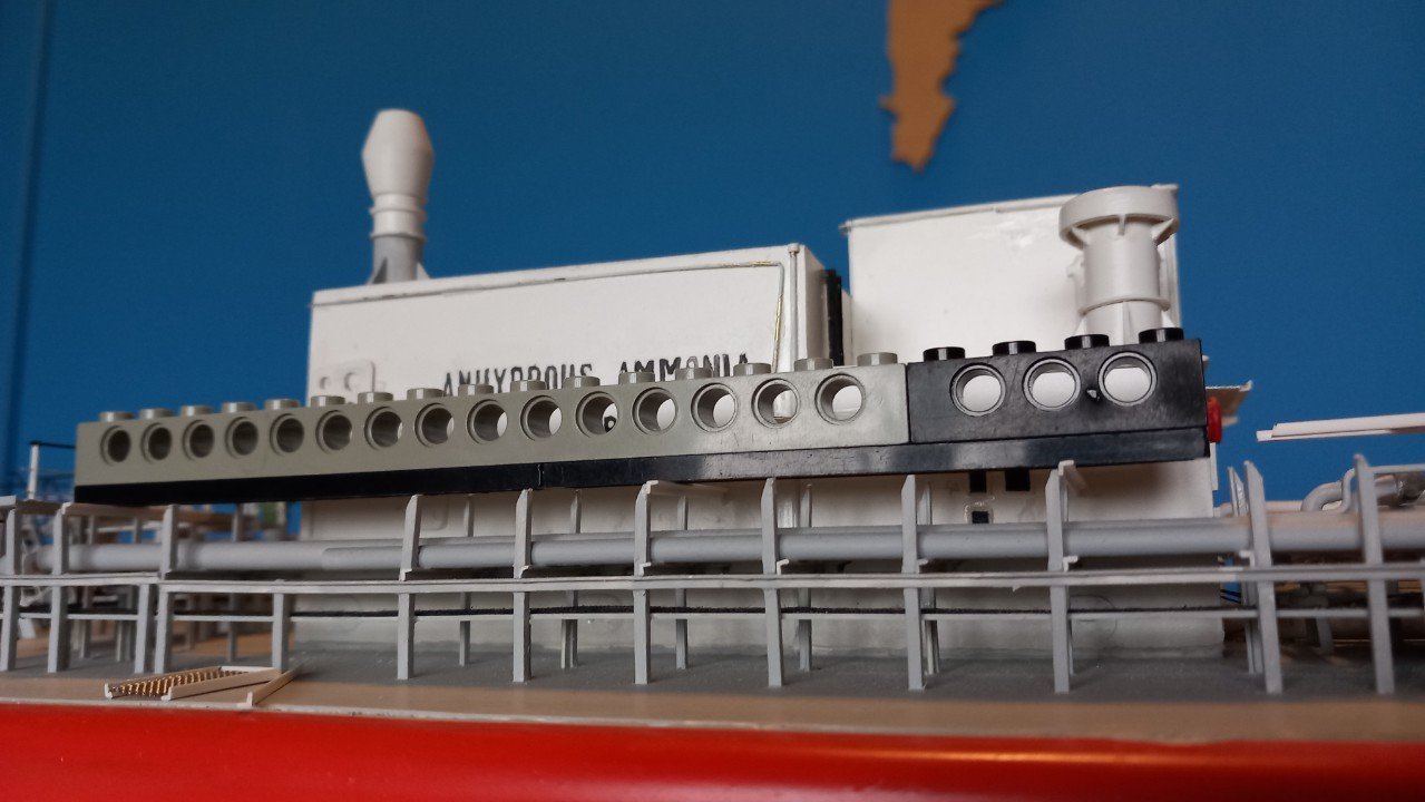
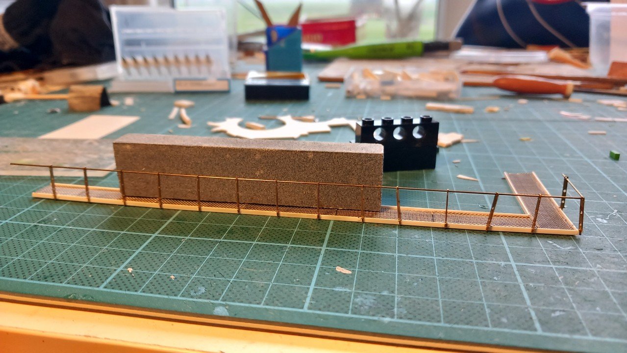
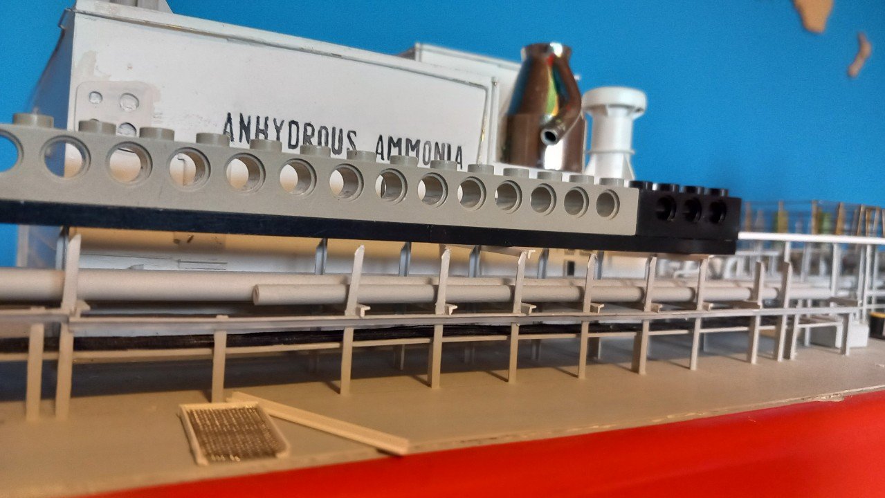
Hi @Keith Black, seemed to have missed that last message. I tried heating as well, but it in most cases it doesn't work too well. In some diameters, I only have tube available, and this collapses when you heat it. With full rods it works better, but still often deforms when heated and bent. Difficult to control the process. In any case, I'm working on a second ship for a commission, but can't really find much motivation. That said, I have put myself a deadline and know that I'll make it, so in the meanwhile I'm continuing slowly with Chaconia. I stopped at the last part of the catwalk. In a sense this is the part I've been working towards the last few years. It should be at the same level as the forward part. First I mounted the forward transversal support, entirely on the left in following picture. I then continued with one almost entirely on the back, visible below the center hole of the black lego block in above picture. I then had my level. That's where the Lego came in. I was looking for something light, straight and long. Those are properties of Lego, whike length is nicely adjustable. Once I had my Lego beam in place, I then continu (ed) with the beams in between. You can see one in the center of the Lego below. I glue them while pushing against the Lego on top. In above picture you can also see part of the pipe penetration to the deck house bulkhead. A part I've built some 14 years ago, but never got to mounting. In the meanwhile I'm also mounting the railing on the catwalk itself. Before actually mounting the catwalk, I'll need to make the connection between the existing piping and the newly mounted bulkhead penetration as well as mounting some small platforms.
-
Javelin reacted to a post in a topic:
Spam in member message section?
-
Javelin reacted to a post in a topic:
Spam in member message section?
-
Javelin reacted to a post in a topic:
HM Brig Badger by ERS Rich - Caldercraft - 1/64
-
Javelin reacted to a post in a topic:
Columbia 1835 by Glen McGuire - 1/400 - BOTTLE - Steam Packet
-
Javelin reacted to a post in a topic:
Steam Schooner Wapama 1915 by Paul Le Wol - Scale 1/72 = From Plans Drawn By Don Birkholtz Sr.
-
Javelin reacted to a post in a topic:
HMS Montague 1779 by garyshipwright - 74-gun Alfred-class
-
See @Keith Black, there's a lesson to learn here for you too. 3rd post in the topic and Glen is already starting his paddle wheels. Really no need to wait for the last part 😃 Beautiful hull Glenn. Did you rely on the self adhesive coat (to glue to plastic hulls) from Artwox or did you apply normal wood glue as well?
-
Good to see you back Nils, hopefully you are fully recovered and may the health issues stay away for a while! Beautiful work on those railings, never an easy task when you try to do it in one piece!
- 313 replies
-
- 5
-
-
- lightship
- Feuerschiff Elbe 1
- (and 1 more)
-
Great job Keith, happy to see you bit the bullet and made those wheels! They, along with the rest of the build, came out brilliant.
- 360 replies
-
- 3
-
-
-
- Billy
- sternwheeler
- (and 1 more)
-
Well I'm in! A pretty large hull indeed. I am surprised there are so few models around of this iconic vessel. Looking good so far, love the idea of the partially raised propeller.
-
Great new project. However, I doubt the ship in the picture and the one in the painting are the same... I would rely on the painting more, since it clearly shows Columbia on the paddlewheel cover, while the picture doesn't really give a clue to the pictured ship's name....The superstructure with bridge on top etc, seems very different from the painting. Of course it could be an upgraded, later version of Columbia in the picture. The bottle is indeed not something an SIB builder would choose, since that long neck will restrict movement of any tweezer or tools you're about to use. Not very convinced on the ornamental top and bottom of that bottle. It looks like a good framing, but I'm somehow scared of those being a bit too empty and leaving the model appear too small for that bottle. You're "simulation" however looks good so far in that (or any other) regard. Looking forward to the way you'll handle the challenges posed by that neck.
-
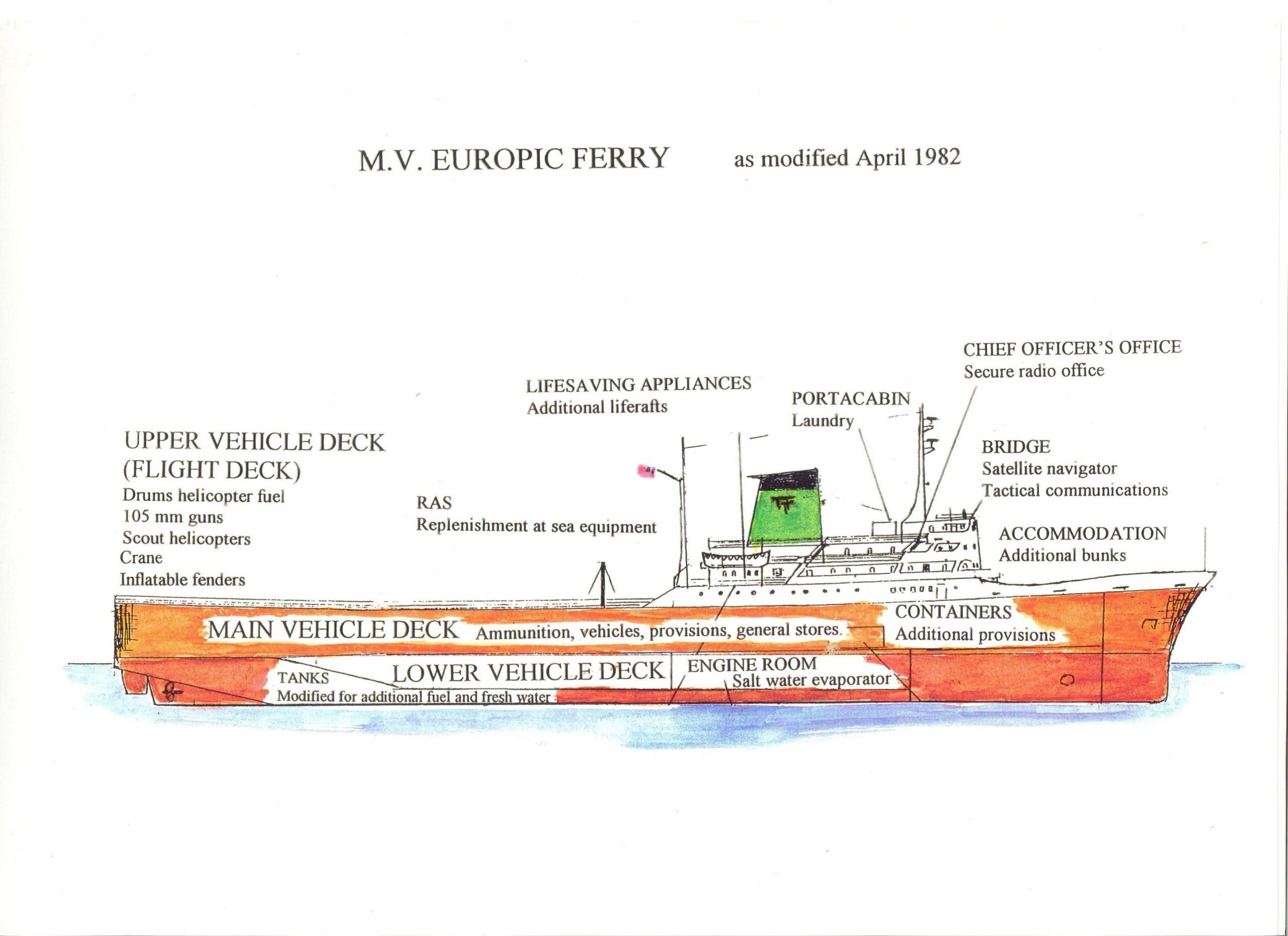
You're welcome Ian, with regards to loading something like this, I believe they drive a car in, turn it inside, so the car front faces the stern ramp and drive it towards that ramp on the extreme port side or starboard side. The next car does the same and parks behind the first one. Third comes next and so on. Perhaps two lanes like that. Next lane I assume can stay without turning. During discharge the first two lanes, portside or starboard, can then drive straight out, creating space for the next lane to turn and then drive out. Not sure if that makes any sense.
- 24 replies
-
- 2
-
-
- ferry
- Europic Ferry
- (and 1 more)
-
Is the RCN weaponry, more specifically the SSM and RAM equipment supposed to be installed in these positions? The RAM not being centered I can understand, but I'd at least have expected the SSM (Kongsberg NSM?), to be devided between Portside and Starboard side?
- 63 replies
-
- 1
-
-
- Type 26
- City Class
- (and 2 more)
-
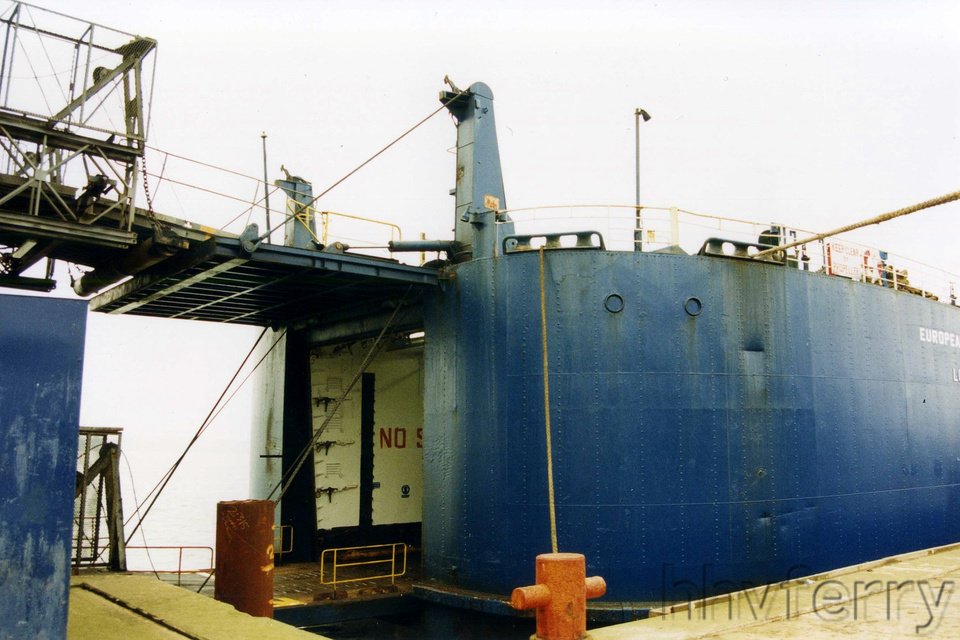
So I had a look around and it's pretty clear to me now. First indication is in this drawing (from: https://www.legasee.org.uk/veteran/chris-clarke/) In the above you can see the ramp on the main vehicle deck going down (starts above the word Tanks and lands below the L from Lower Vehicle Deck). It could apparently be hoisted up to close the main vehicle deck (I assume for a watertightness /safe freeboard reason). This can be seen on the General Arrangement plan as posted in some facebook page (you can view it without an account by searching it through google. Can't seem to link it here... As for the stern ramp, it works double. The vessel was loaded in 2 levels. The upper part of the ramp would hinge down and form a bridge to the upper deck, while the lower part of the stern door would hinge down and form a second bridge to the main vehicle deck. You can see the steel wires of the lower bridge hanging outboard on some of you pictures. Hydraulic pistons are normally used press such gates against a seal in the vessel hull to make it watertight. Not sure why they'd use those on the upper deck though. Perhaps a back-up of the wires? This double ramp is quite typical for ferries, but requires a specialised loading quay with an upper level matching or being adaptable to the height of the decks of the vessel.

- 24 replies
-
- 5
-
-
-
- ferry
- Europic Ferry
- (and 1 more)
-
Hi Ian, she'd have 2 masthead lights (she's more than 50m long), one side light on each side and 1 stern light. As for the platforms on the mast , as far as I can tell from the pictures above, I'd say the top one is an S-band (approx 3-3.5m long) antenna, while the other one is likely an X-band antenna (about 1.5m long). 2 radars are required, however the X-band is the only one that is really required (Search And Rescue Transponders /SART work on X-band frequency). The second radar may therefore be either an S-band or just another X-band. It is quite common for ferries and car carriers to have internal ramps between decks, be it permanent ones or hoistable ones. I'll have a look at some pictures of this vessel and see if I can figure something out.
- 24 replies
-
- 3
-
-
-
- ferry
- Europic Ferry
- (and 1 more)
-
She's gorgeous Bob. Happy you continued and eventually finished her. Love the cupboard too! Fits your varied collection well.
- 261 replies
-
- 3
-
-
-
- Victory Models
- Pegasus
- (and 3 more)
-
You've got yourself a follower now. Interesting subject, right down my alley! I do like the dark blue livery as well. But red's fine too, always makes for an eye catcher on the water. Curious where this will go, but I would indeed try to create some access to the front area. Some cleverly hidden and reinforced handles on that superstructure may help to prevent damage if you make it removable.
- 24 replies
-
- 4
-
-
- ferry
- Europic Ferry
- (and 1 more)
-
Fund raising
Javelin replied to Russ2025's topic in Using the MSW forum - **NO MODELING CONTENT IN THIS SUB-FORUM**
Made my donation today using the link. Didn't have any issues... Perhaps not an accepted type of card?