JacquesCousteau
-
Posts
1,362 -
Joined
-
Last visited
Content Type
Profiles
Forums
Gallery
Events
Everything posted by JacquesCousteau
-
 Great work! The ladder especially turned out really nicely, ingenious method.
 -
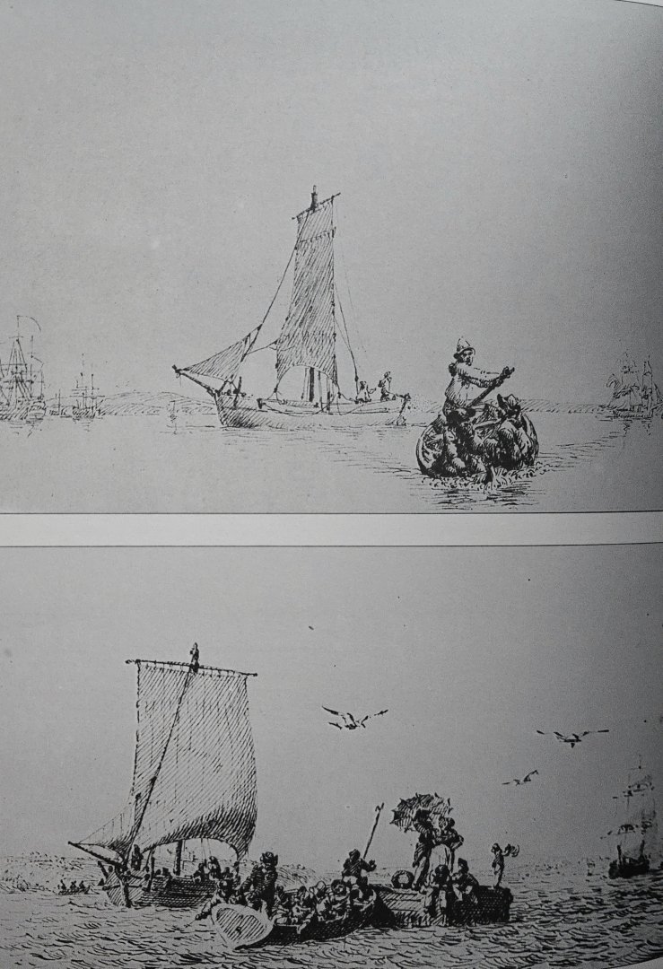
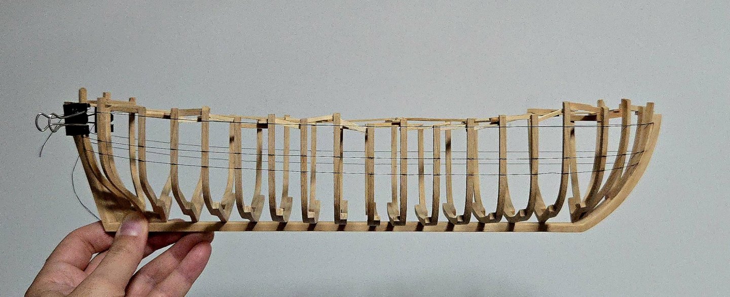
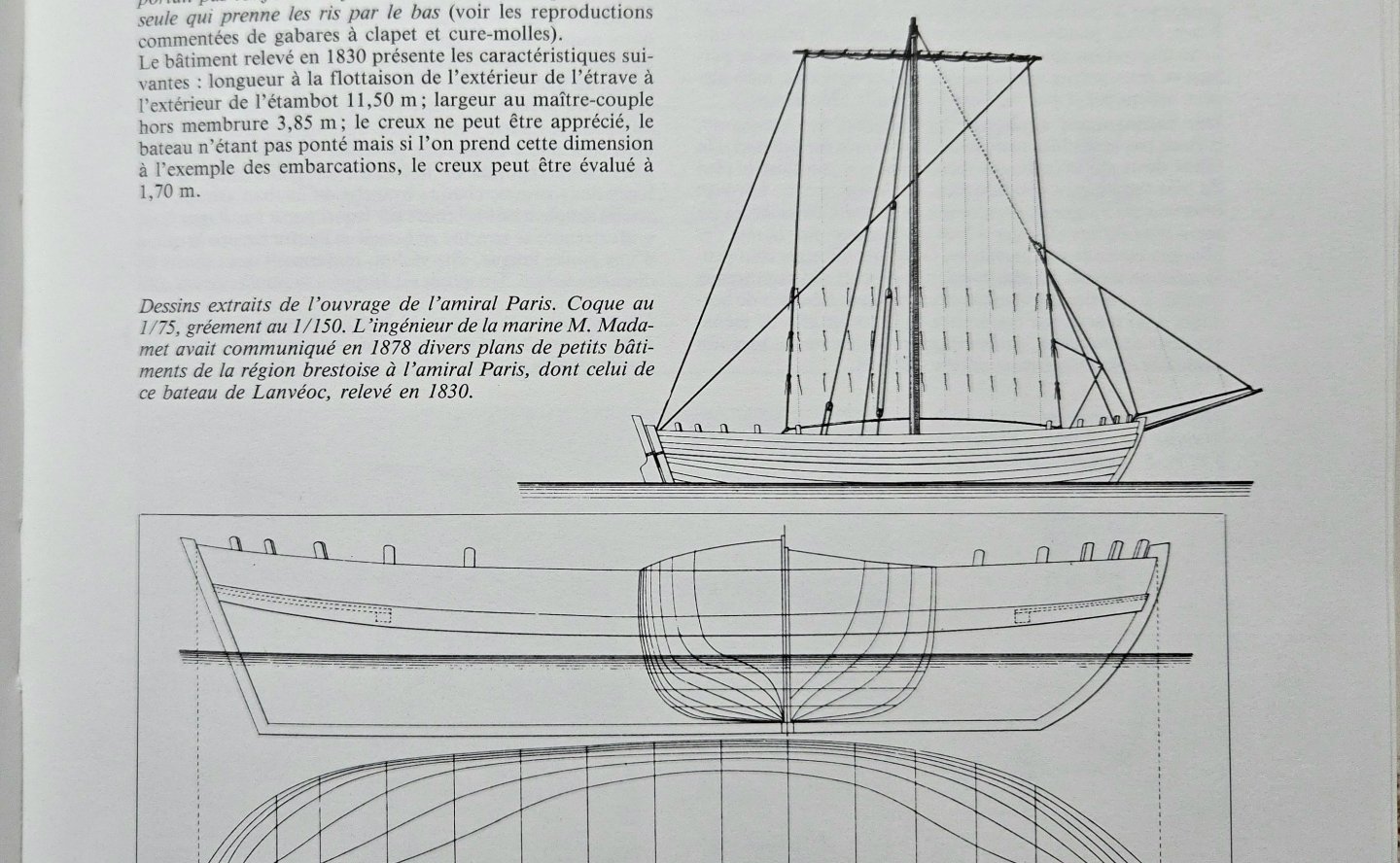
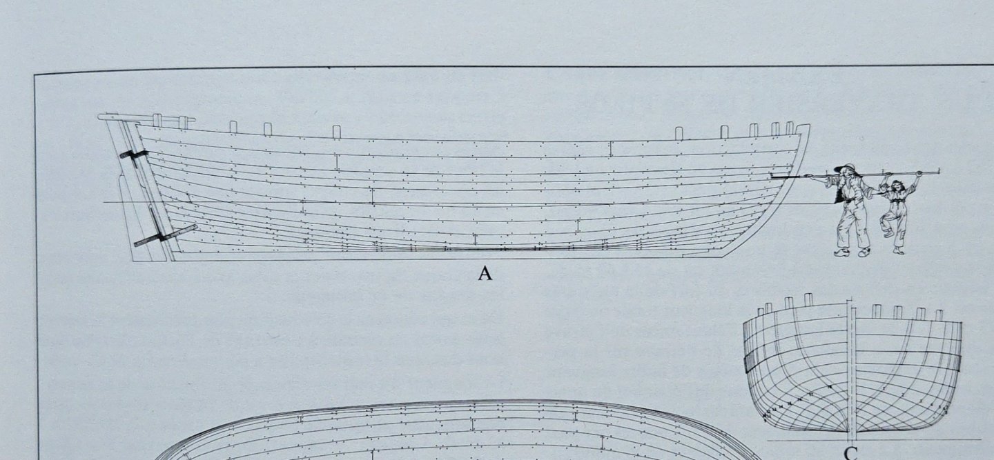
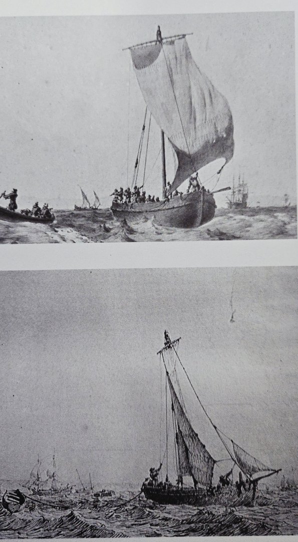
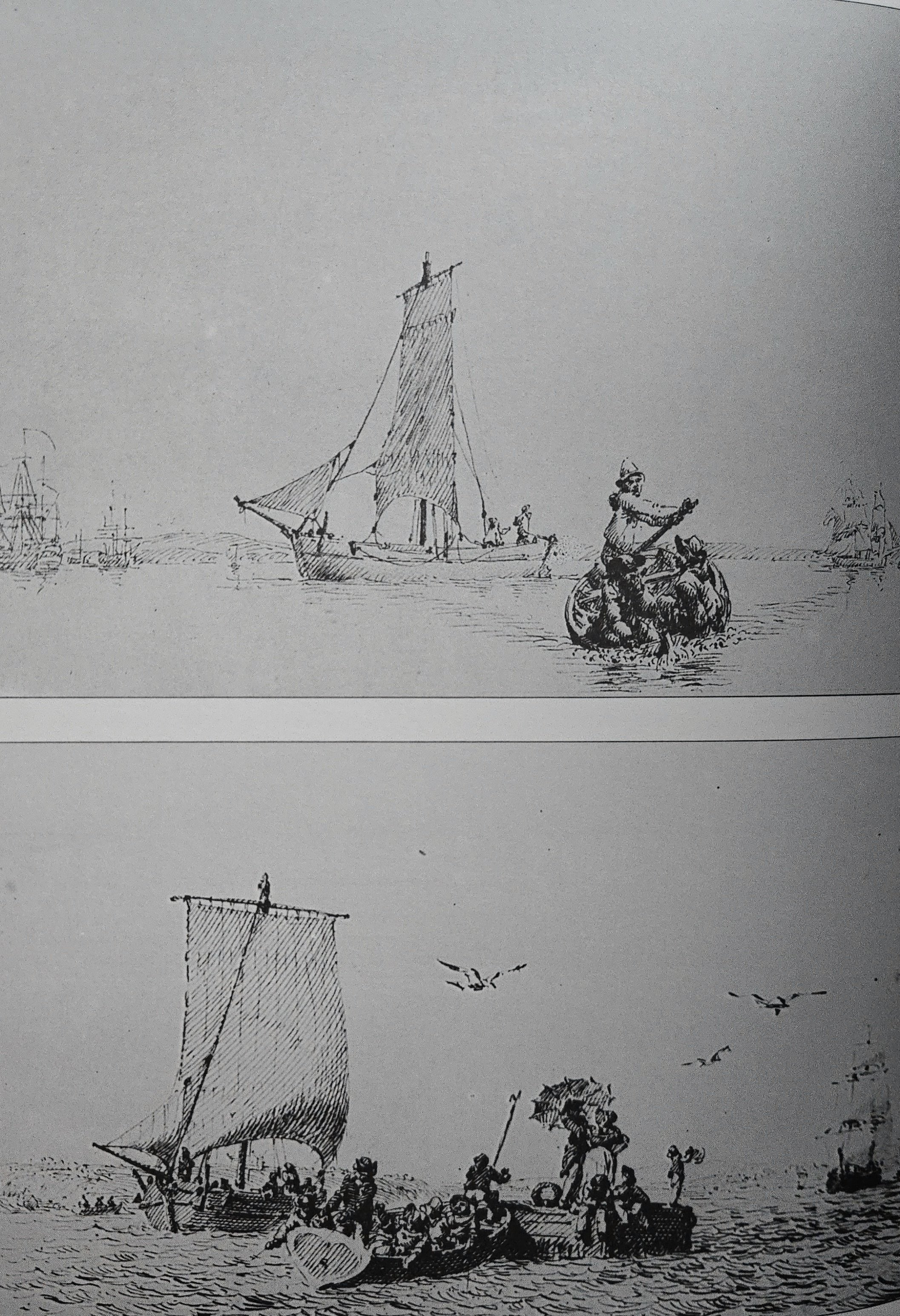
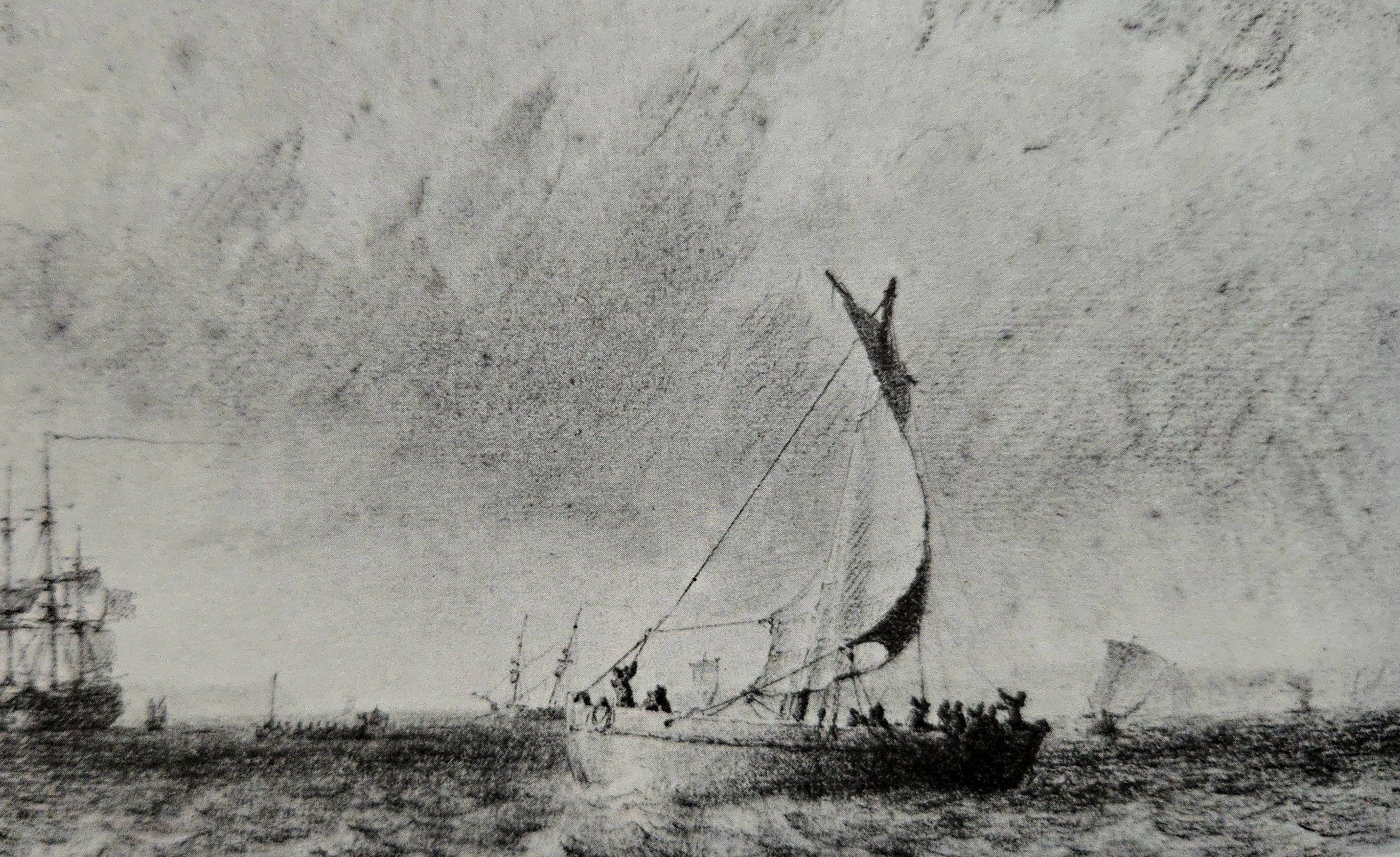
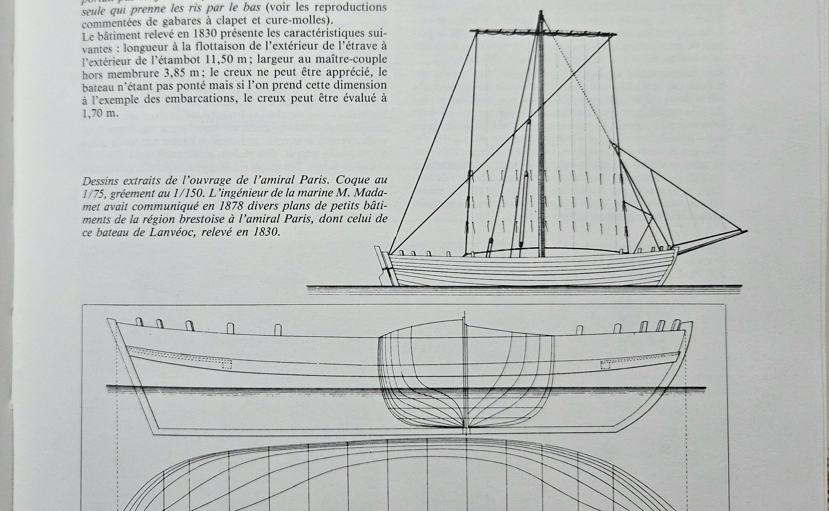
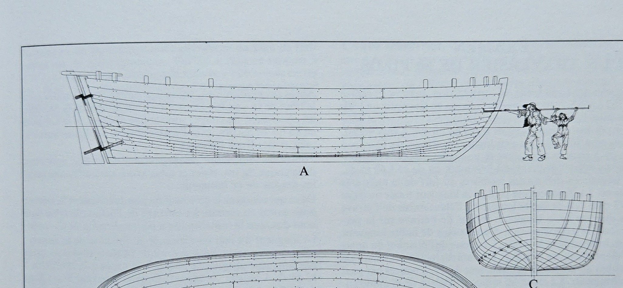
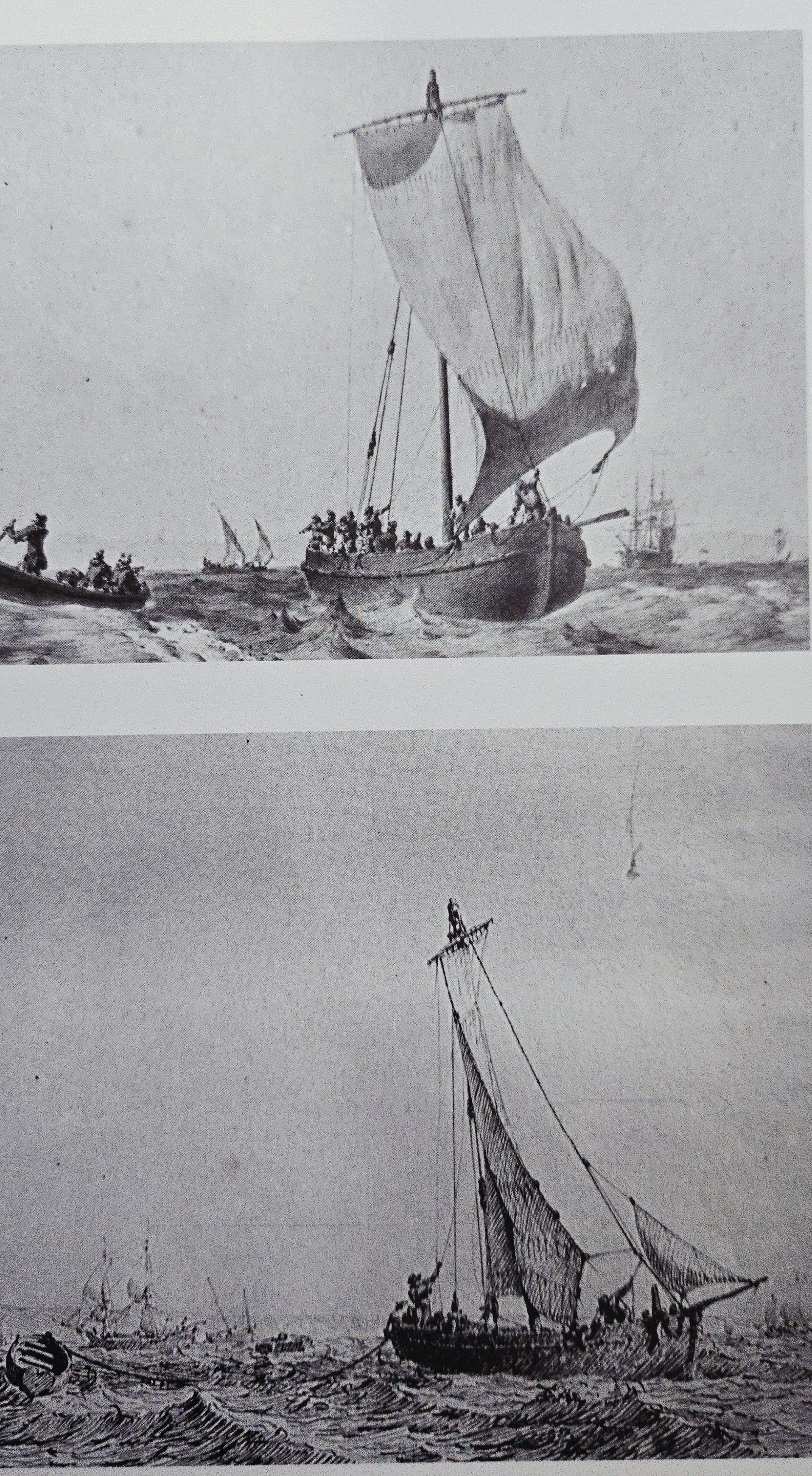
I realized that I had placed the wales a little low, so I had to move them up a bit. It would have been much faster to do it right the first time! In any case, I'm happy with the run of the wales now. I also began marking out the sheer line, following the same method with thread. Here there's a bit of an issue whether I should stick to the monograph drawings or follow the Pâris plans. As can be seen below, the monograph drawings give a nearly flat sheer, with limited rise aft and almost none at the bow. In contrast, the Pâris plans (also included in the monograph) show a bit more sheer--nothing extreme, but it is noticeable in comparison. It's especially clear of you compare the sheer line on the section view drawings. So, which to go with? I feel like the more pronounced sheer is a bit more pleasing to the eye, but I'm concerned about whether doing that will throw anything off with the hull, like the position of the wales. Below I marked out the sheer line with thread (a bit hard to see, sorry) following the monograph plans: And below, I dropped the sheer line a bit amidships to create more of a curve: I'm still deciding what to go with. The Ozanne drawings included in the monograph show fairly limited sheer in some vessels, but rather more in others. Other things I'm thinking about with this build: - I still don't really know what to do about the pump. None is shown in the plans. I guess it could be bailed by hand, but that hardly seems ideal when there's a large cargo load. - Relatedly, I still need to add the limber holes before planking. If I decide to add them, that this--it would make sense to me to include them, but they aren't on the plans. - I remain confused as to why the interior wouldn't be planked, as any passengers or cargo have to stand/be placed directly on the frames or on the inner side of the external planking. - I won't get to the anchor for a while, but I wish I had a better sense of how it would be handled. The monograph includes an anchor drawing and says it would have weighed 200 lbs and that two would have been used. There is no anchor-handling equipment shown, and its not clear to me even where the anchor cable would be tied off. 200 pounds is way too big to just haul up directly by hand, so I assume they would have rigged some blocks to the mast or something, but I really have no clue how they would have gone about it.
- 139 replies
-
- 8
-

-
- ancre
- Bateau de Lanveoc
- (and 2 more)
-
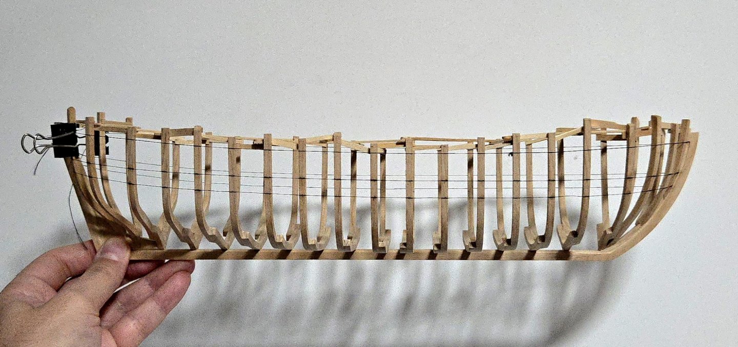
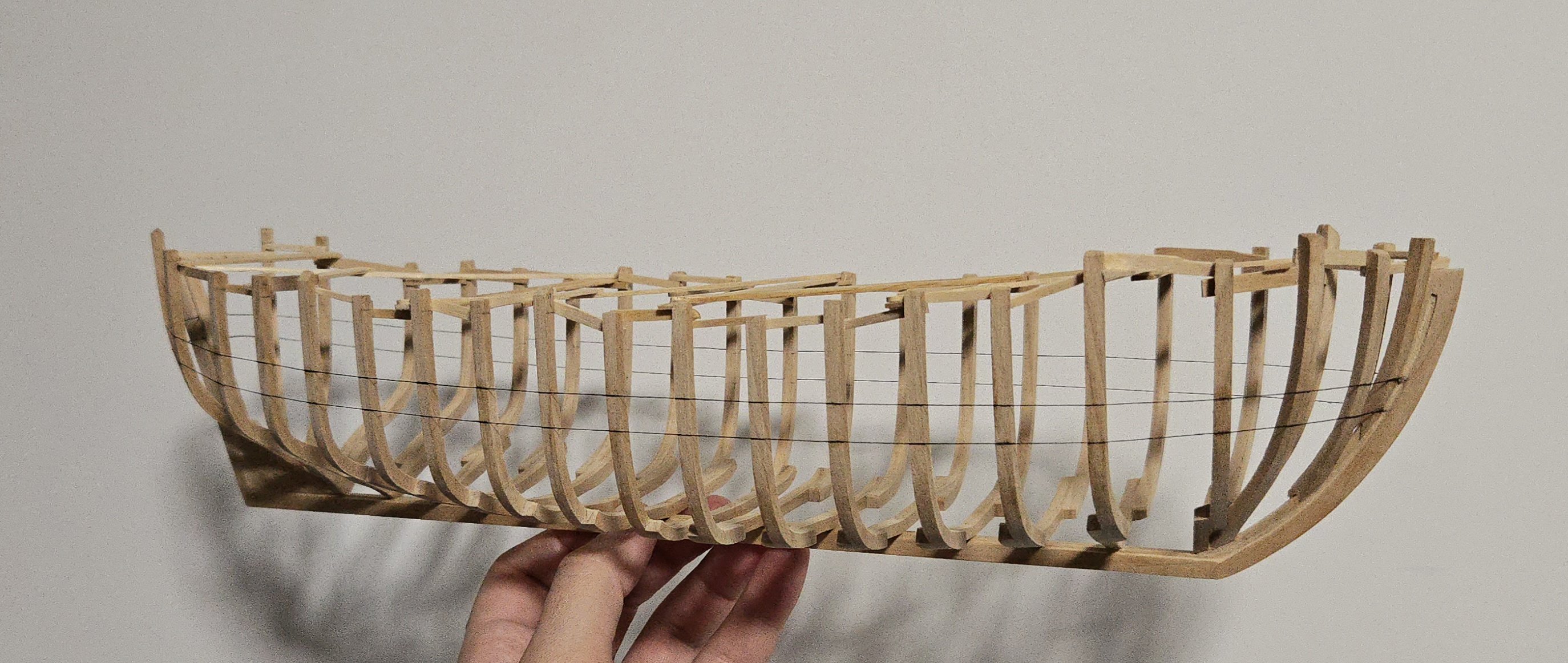
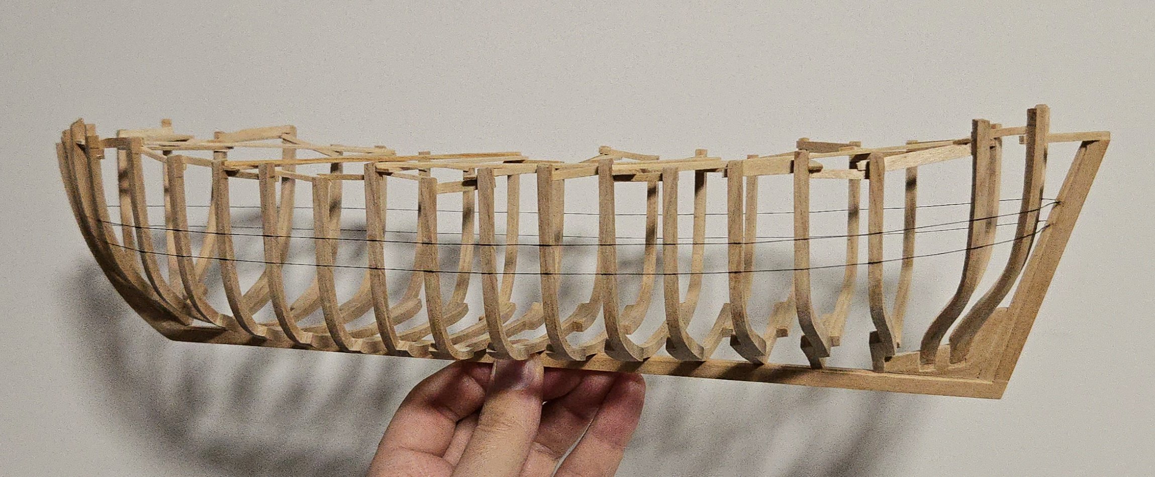
After returning from travel, I had a pretty quiet day unpacking and getting over jetlag today, and I found time to work a bit more on the Bateau. The hull is completely faired at this point. This took a lot of work, and I ended up building up a total of four frames that were just a bit too low. As earlier, I used multiple layers of wood shavings to build them up. I then began to work on marking out the wales. I first marked out the location of the top of the wales as best as I could from the plan drawings. Rather than do this on every frame, I just marked several along the hull. I then glued a black thread along the line, adjusting its run as necessary to get it fair. I then added a second line for the bottom of the wales. I'll let it sit overnight and come back to it with fresh eyes tomorrow. Photos can also help with picking up issues I don't notice when holding the model.


- 139 replies
-
- 8
-
-
- ancre
- Bateau de Lanveoc
- (and 2 more)
-
Nice work, it turned out really great!
- 90 replies
-
- 2
-

-
-
- Friendship Sloop
- bluejacket shipcrafters
- (and 1 more)
-
Since my earlier post, I received an email with all three judges comments in a single document. Thank you to the judges, your comments were very informative!
-
Thanks!
-
I was curious about ordering the HMS Triton project, but I don't see it in the NRG store anymore. The url still exists, but directs to the new capstan project. Is the NRG no longer selling the Triton project plans? Here's the url: https://thenrgstore.org/collections/plans-and-projects/products/hms-triton-plan-access-msw-copy
-
Very nice work!
-
Great job on the model, and that coffee table is very cool!
-
Thanks all! Just to be clear, we got married a while ago (legal paperwork a few years ago, ceremony and celebration this past summer), our honeymoon was just delayed quite a bit.
- 139 replies
-
- 8
-
-
- ancre
- Bateau de Lanveoc
- (and 2 more)
-
Are there any plans to send the judges' comment sheets to participants?
-
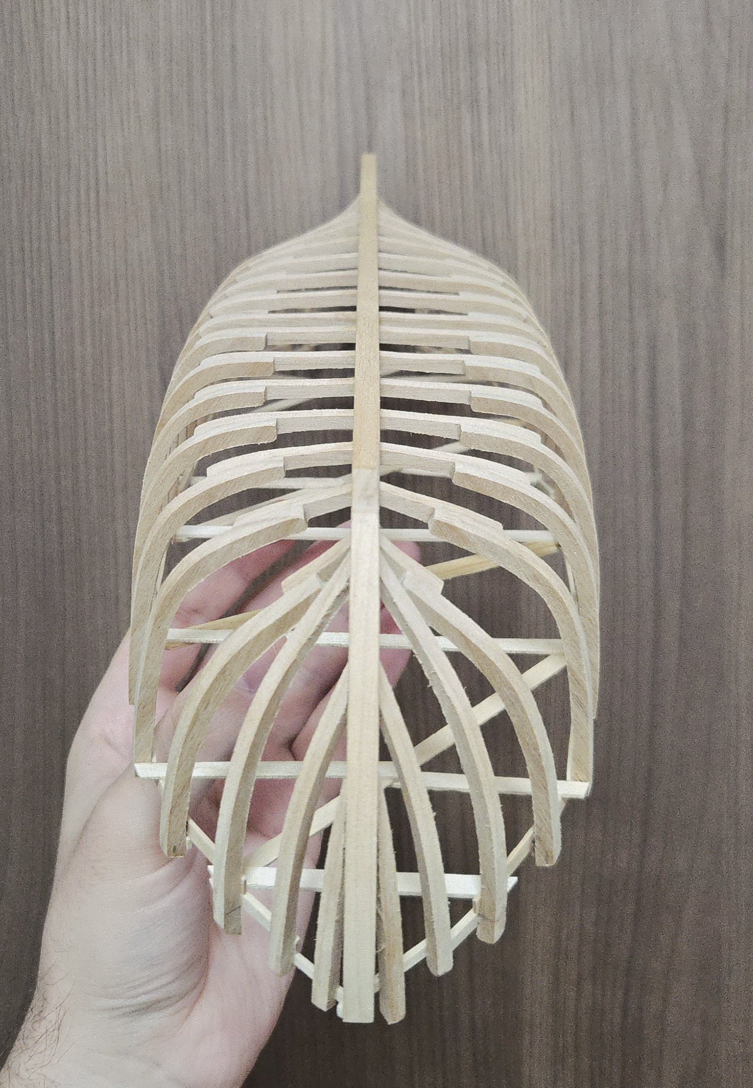
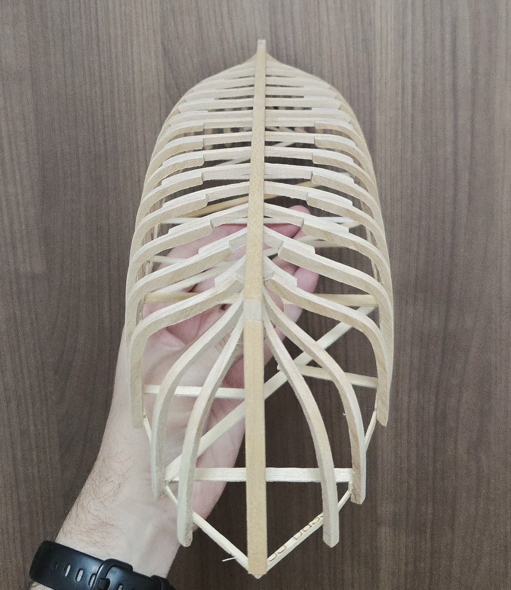
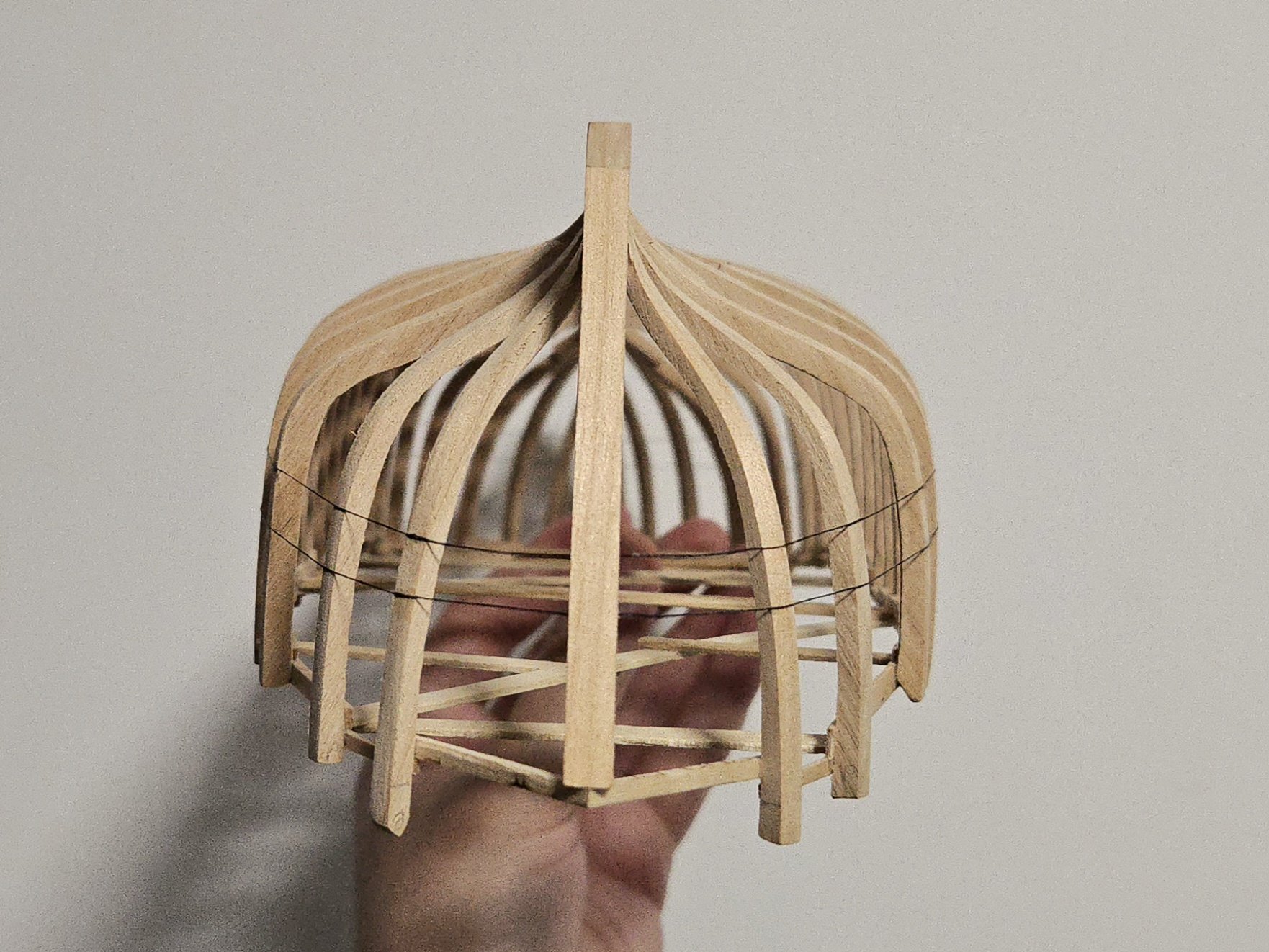
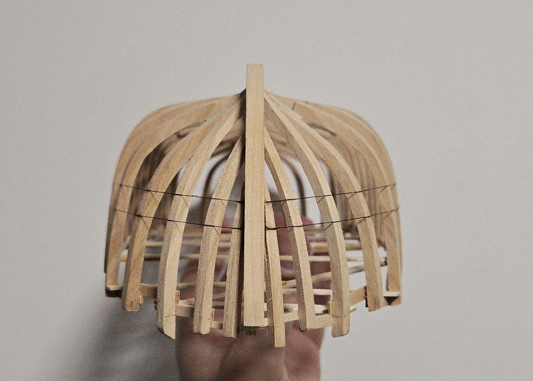
Not a very exciting update. I was able to get a bit more fairing in today, and I think the hull is almost there. I think one more session focused on the starboard stern, and one last session for final fairing, should get me there. While I'm happy with how the bow has turned out, I'm still not totally sure on the stern cant frames. I keep snapping battens trying to check. On the other hand, an already-bent bit of scrap seems to fit fairly well, and the plans do seem to show quite a curve there, so I think I'll just have to pre-bend the planking there. In any case, it may be a while before I post updates. We'll be traveling for our honeymoon soon, then visiting family for Christmas. It may be January before I can finish fairing and finally start planking. In the meantime, I'll leave things off with the photo below, which I thought nicely showed the curve of the hull. (It's funny that it automatically adds that it's AI-generated in the corner of the photo. To disclose: I used an editing tool to erase something from my desk at the top of the photo, not to generate the model.)
.thumb.jpg.5b00e65a4e7d9bb0bf1fc2958abdea24.jpg)

- 139 replies
-
- 12
-
-
- ancre
- Bateau de Lanveoc
- (and 2 more)
-
Very impressive work!
-
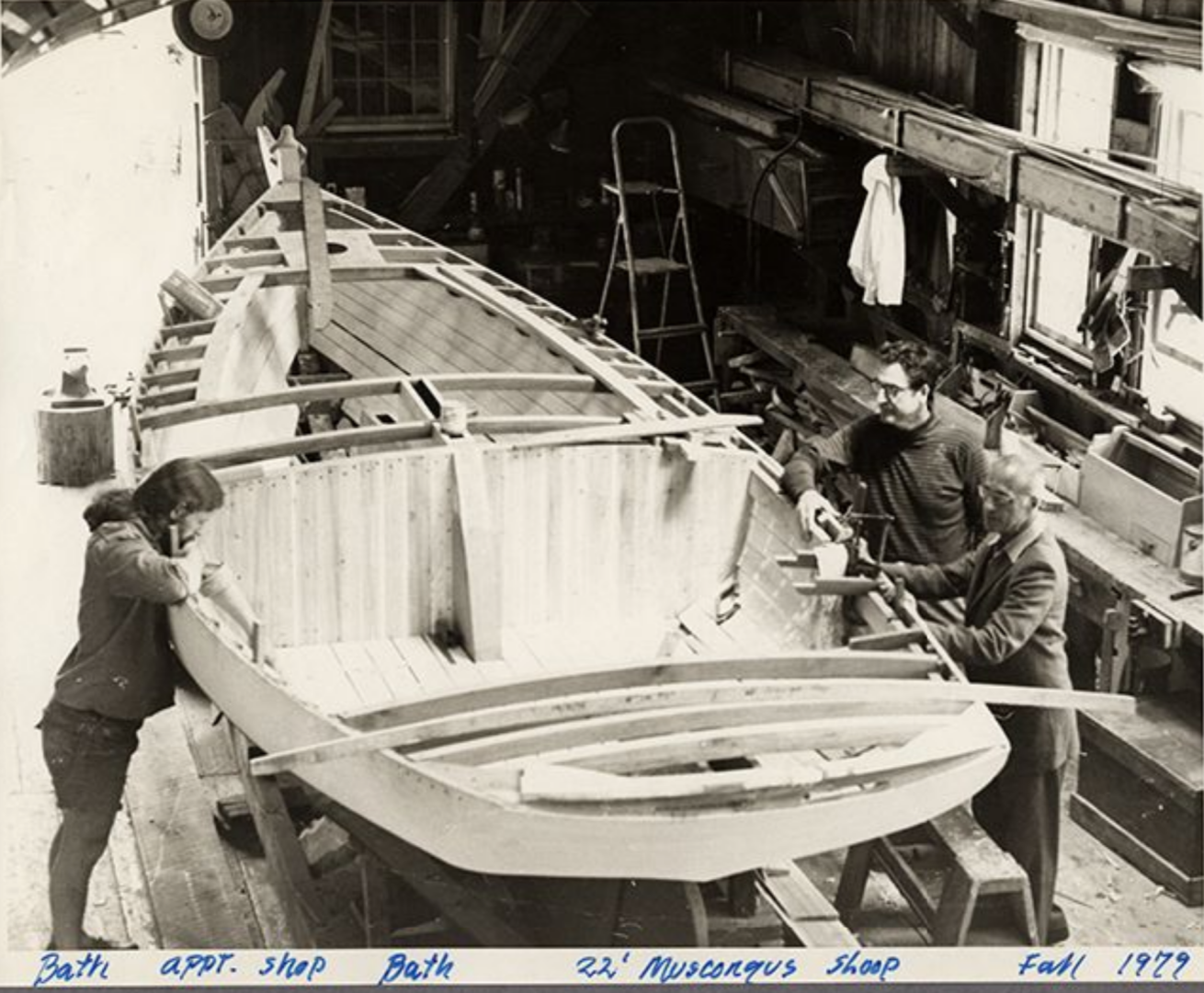
Very nice work, the bilge pump is a great detail to include! (And one that I might steal for my own build, with due credit in the build log of course). I had been wondering about the pump myself but didn't see anything about it in any of my sources, but using the Friendship Sloop plans instead to find it is a great idea. I notice that the Friendship Sloop seems to have the pump a bit further back in the cockpit. Looking around in photos, though, I noticed a detail I had previously missed. In the photo below of the centerboard sloop Charity, which was built in the 1970s reconstructed from Chapelle's plans, there seems to be something protruding from the floor planking--a hole with something sticking out of it?--just off the bulkhead to the port side of the centerboard case (which, unlike on the model, projects a bit into the cockpit). I would guess that that's the space for the pump, although I don't know if they went for a more modern type in the reconstruction. In any case, it's right where you added your pump. Source: Penobscot Marine Museum digitized photo collection.
-
Congratulations on finishing your first first planking! If those are 1/16-inch planks, I wouldn't be too concerned about sanding through them. You may want to put some wood filler over the low parts first, though--just a thin layer, you can always add more later but it's a pain to sand through if there's too much.
-
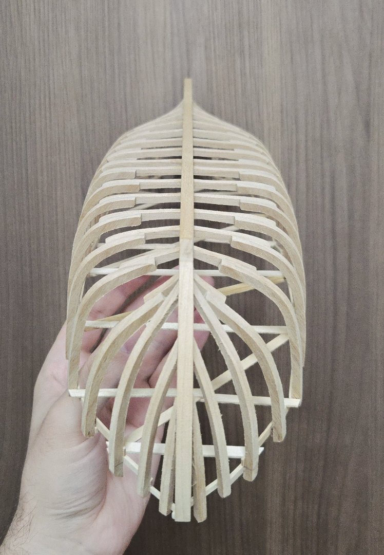
Nice start! How big is the model? It looks like it's around 10 inches long? The large number of closely-spaced bulkheads is nice, too often you see so few widely-spaced ones that planking can be a challenge.
- 38 replies
-
- 2
-
-
- Fischkutter
- Laser Creation World
- (and 1 more)
-
Thanks, Eric! Your capstan turned out great and your build log has been really helpful. It's definitely a challenging project!
- 32 replies
-
- 5
-
-
- NRG Capstan
- NRG
- (and 1 more)
-
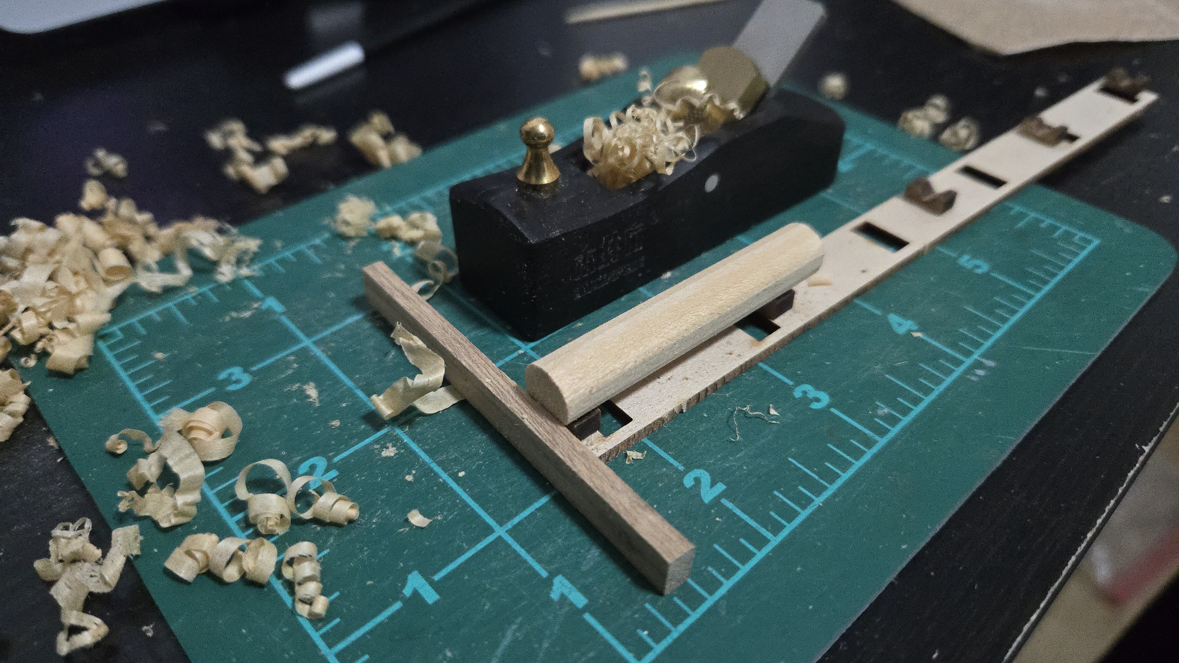
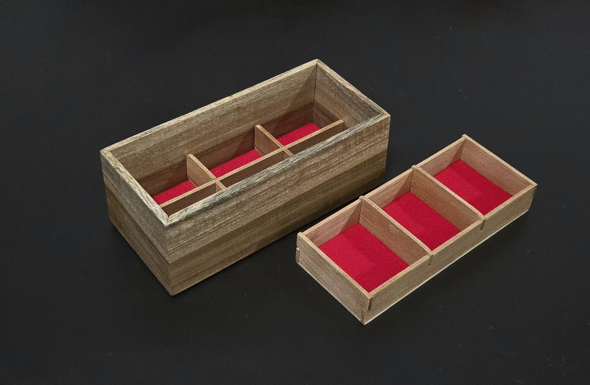
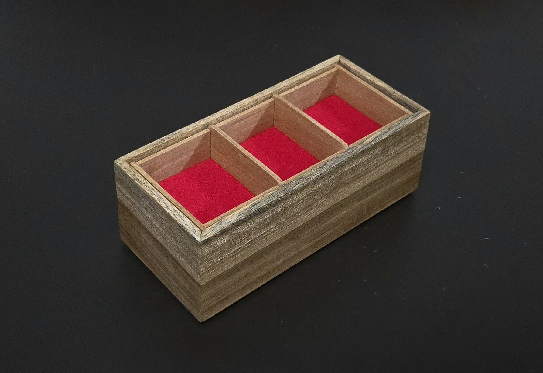
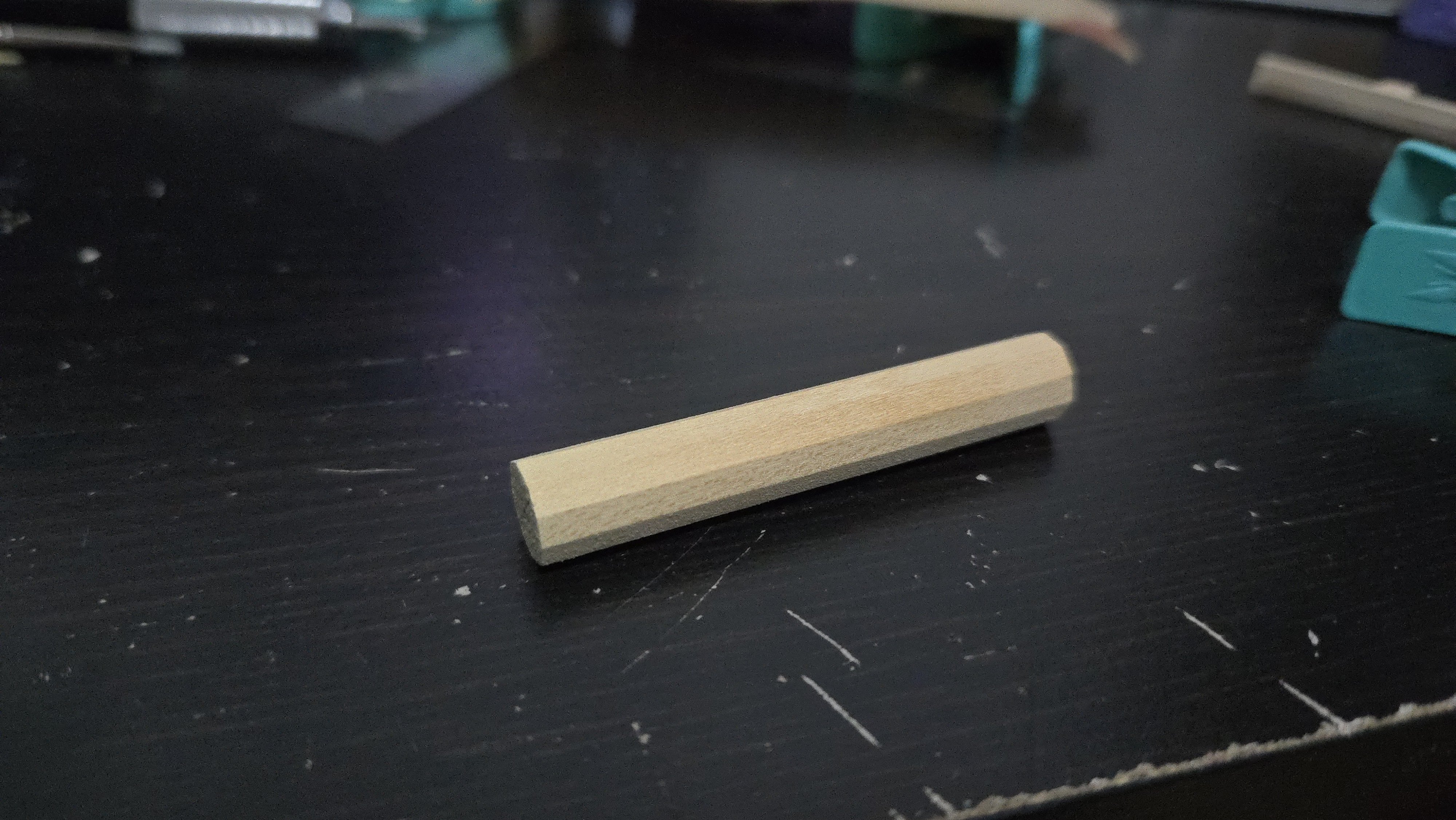
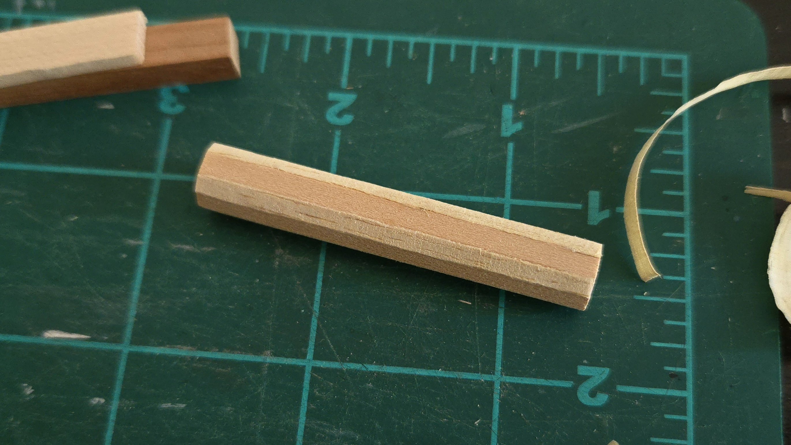
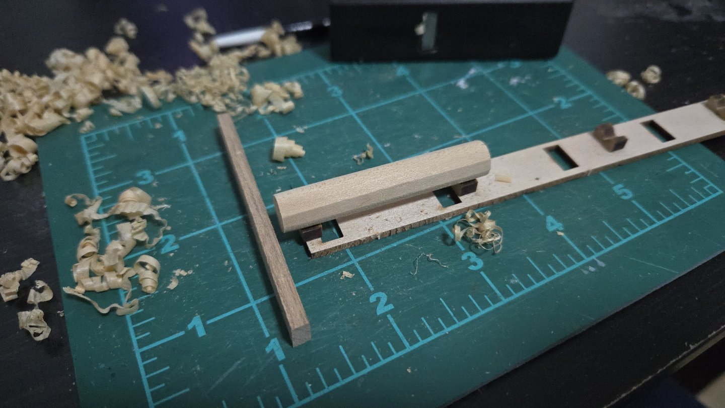
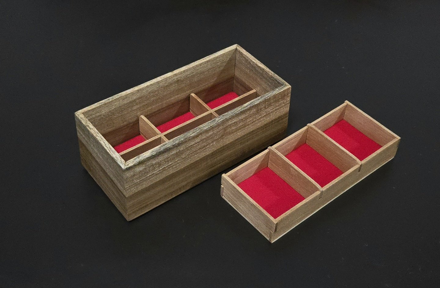
Thanks, all! I haven't had time yet to try to cut the manzanillo down to the right thicknesses, but I have started work on the internal barrel of the capstan. This is a 10-sided shape. While the advanced instructions call for shaping it as one piece with a mill, the intermediate ones use a very interesting method of building it up with 10 wedges--half of them slightly larger than the others, in order to create grooves for the placement of the whelps. The wedge method is really neat, and seems like it would work well. But, it's very dependent on getting a lot of pieces of wood in the exact right size (and that's before planing them into even wedges). With the right power tools, this would be trivially simple. Without power tools, and needing to hand-plane each part to the exact proper thickness, making 10 wedges, five in one side and five in another, is a huge task that would take a ton of time. Doing that for the whelps, chocks, and drumhead will already be tedious and challenging enough as it is. So, I decided to simplify. @Cathead was able to make a great capstan barrel just by chiseling a dowel into ten sides, and I tried to do something similar. I took a portion of square basswood stock, a bit over-long, and first rounded it, almost like I was making a mast. I then marked the centerpoint, divided it into four even quadrants, and eyeballed the lines to make it a 10-sided figure. I then used the mini-plane to shape it. The result is undoubtedly less precise than the wedge-built method, but seems like it should work. Of course, one issue with making the barrel from basswood is that it will contrast sharply with the manzanillo I'll be using for the rest of the capstan. My answer for this is to plane off shavings of manzanillo and glue then as a veneer on every other side of the barrel. As can be seen, while the manzanillo planes fairly well, the grain may be a little prominent for less stylized modeling. I also have had a bit of trouble getting a smooth edge where I trim it off. I think I'll be doubling the "veneer" so I can get a nicer edge and have enough thickness to sand out the planing marks. In any case, I haven't advanced that much on any modeling for the past several days, as I've been using the xochicuahuitl--the same wood I used for the capstan bars--to make a jewelry box as a Christmas gift for my wife. I have to say that I'm very pleased with how it's turning out, although the fabric bottoms turned out thicker than I planned and I'll need to cut down the lower dividers a bit for the lid (not yet built) to fit properly. It's my first time using shellac, I really love how straightforward it is to apply and build into a nice finish. I'm amazed at how smooth it ended up. Apologies for the non-modeling photos!


- 32 replies
-
- 9
-
-
- NRG Capstan
- NRG
- (and 1 more)


.jpg.cda4c331096900f0ec9b6d604373312b.jpg)