JacquesCousteau
-
Posts
1,362 -
Joined
-
Last visited
Content Type
Profiles
Forums
Gallery
Events
Everything posted by JacquesCousteau
-
 I think Syren offers internally-stropped wooden blocks, although I don't know if they're the right size. Another option would be to fake internal stropping, as done here:
- 48 replies
-
- 1
-

-
- San Francisco Bay Scow Schooner
- Scow Scooner
- (and 1 more)
-
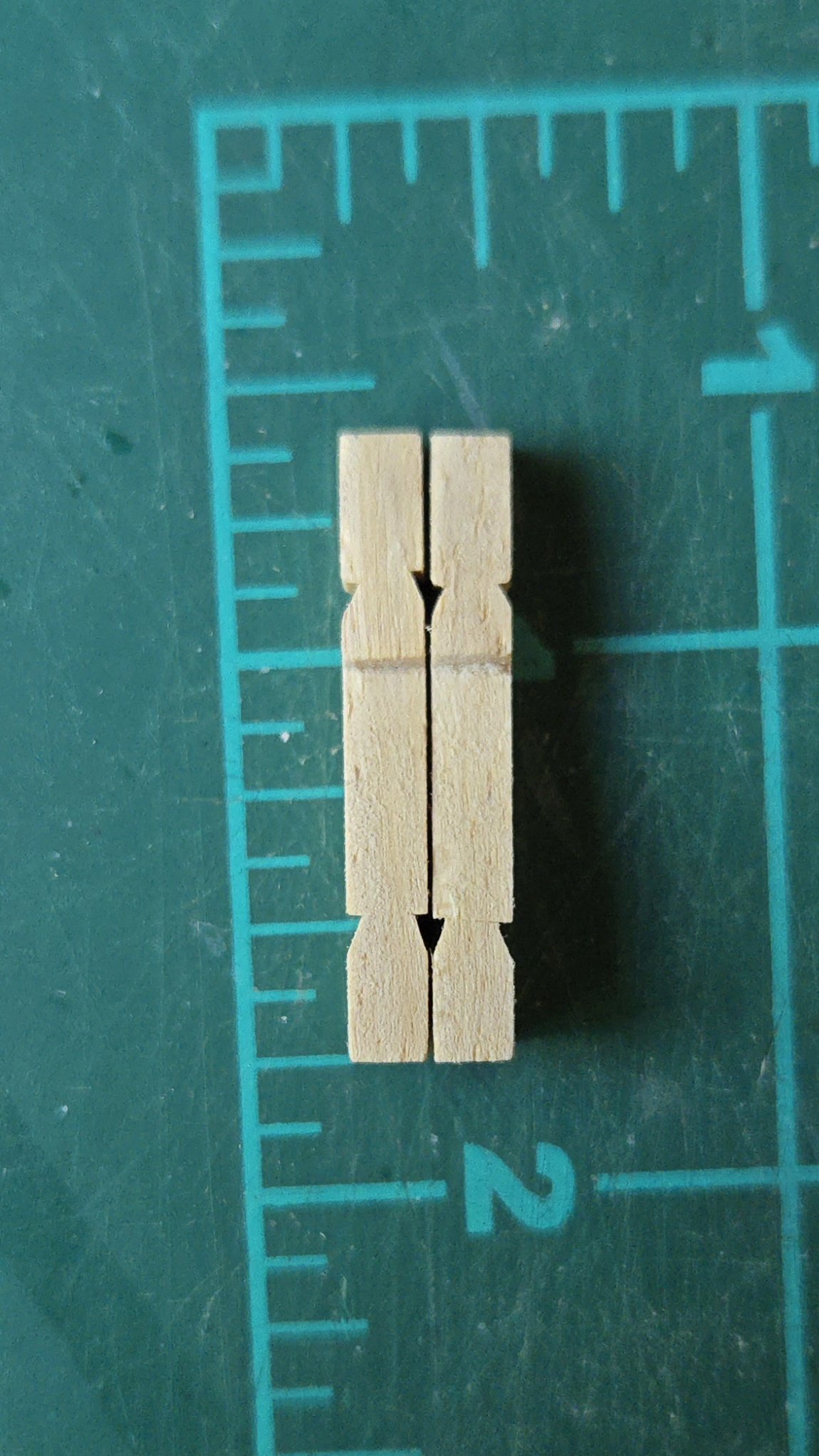
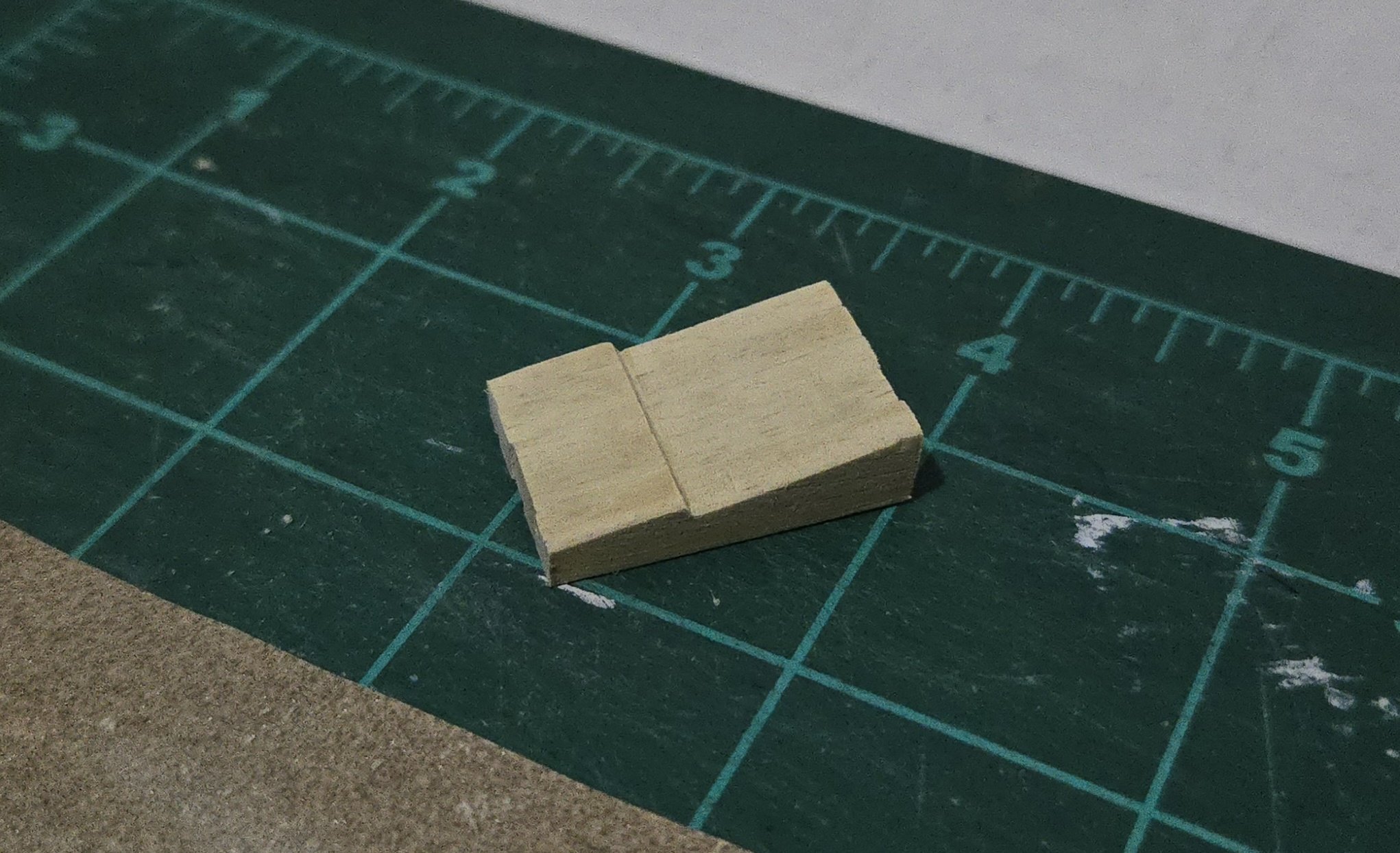
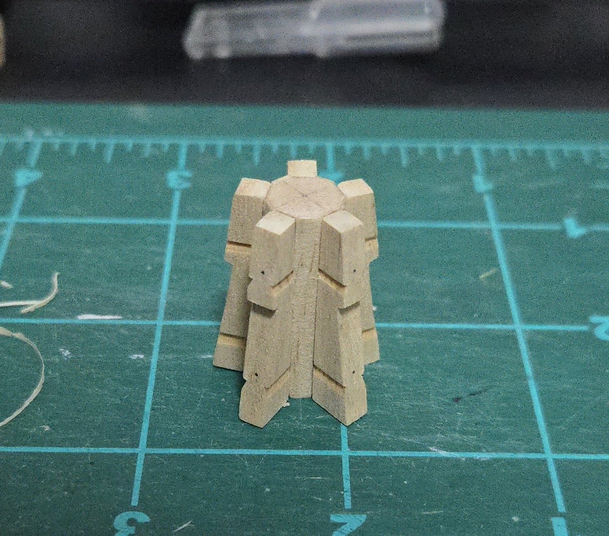
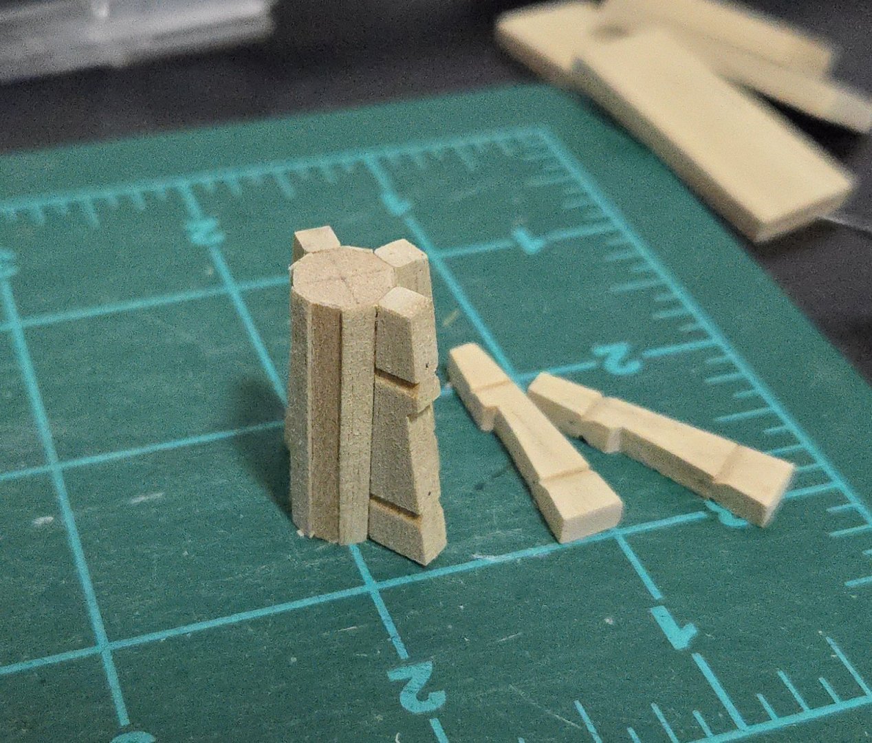
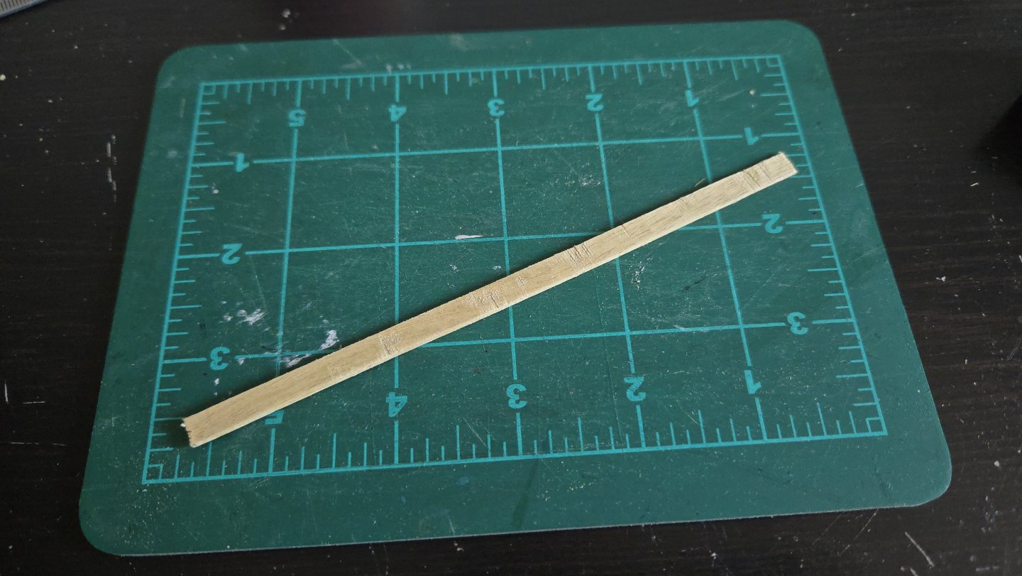
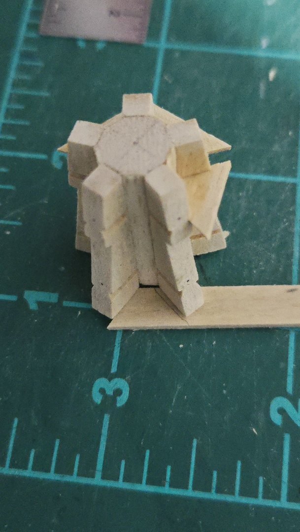
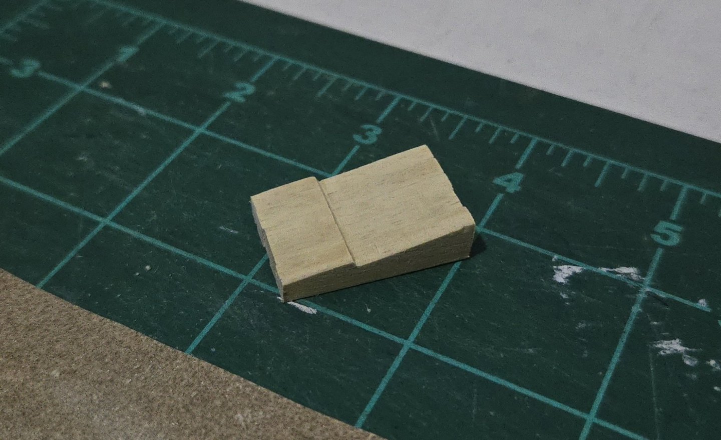
Once back in Mexico City, the next step was to add an extra layer of manzanillo shaving to the spaces between whelps on the barrel. As I noted above, rather than follow the wedge method given in the instructions, I followed @Cathead's lead in making the barrel from a different wood and building it up to create slots for the whelps. He used veneer, which would undoubtedly be a better option than multiple layers of thin shavings, but given my limited milling equipment, shavings are much easier for me to make. I also cut the barrel to size. I then began adding the whelps. In the meantime, I also did a quick test with scrap and found that the shavings seem to absorb linseed oil just fine--I was worried they would be too thin and glue-saturated to do so. At this point, the assembly is slightly over-tall, and it needs to be sanded at the top and bottom to fully even everything out. Before I do that, though, I wanted to add the chocks in order to strengthen the assembly. The chocks need to be quite thin, and I wasn't sure how to go about that. I briefly tried planing down from one of the chunks of 1/8-inch thick "milled" manzanillo, but I realized it would take forever. Instead, I used a coping saw to cut a fairly thin (marked at 3/32-inch thick) strip off the edge of a length of board. Below, it's midway through planing to smooth it out. My saw blade wandered a bit and one side ended up a bit thin, but in this case, that worked in my favor. The upper chocks should be noticeably thinner than the lower ones. So, I cut off the thinner side and planed and sanded to a consistent thickness. To cut out the chocks, I decided against using a template, as my barrel assembly is a bit off from true and every whelp is at a slightly different angle. Instead, I traced each shape directly on the wood, cut slightly oversize, sanded in the bevel, and adjusted to fit. At the moment, I have the upper, thinner chocks glued in place. They're all oversized. Once the glue dries, I'll carefully shape them, and then get to work on the slightly thicker lower chocks.

- 32 replies
-
- 10
-
-
- NRG Capstan
- NRG
- (and 1 more)
-
I'm pretty sure they're the bands. On my build, I added them at this point: They sit on the outboard side of the planks, following the sheer.
- 45 replies
-
- 2
-
-
- Dory
- Lowell Grand Banks Dory
- (and 3 more)
-
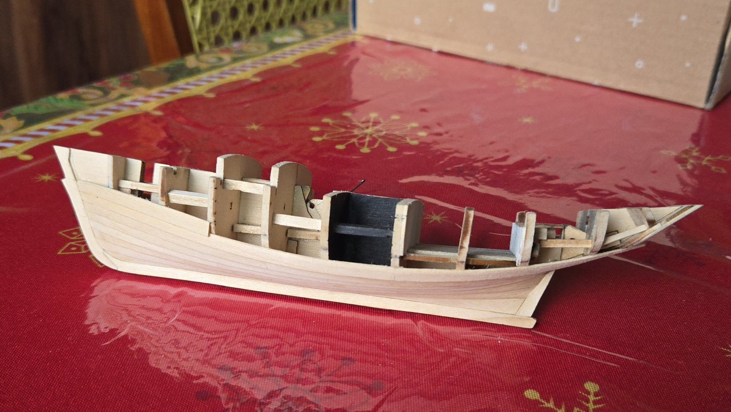
Very nice work, it's great to see this odd little vessel coming together! With the details added, I was going to say that it's really starting to look like a boat, but to be honest, I think it looks more like a floating house--I mean that in the best possible way, of course.
-
Very nice work!
-
Very sorry to hear this, thank you for the excellent cherry lumber and best wishes in retirement!
-
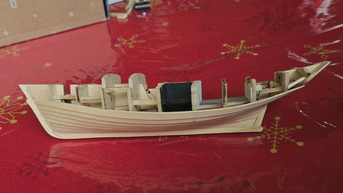
Thanks, all! I next marked out the remaining strakes. The uppermost looks narrower because it will extend up to cover the edge of the false deck. And I added the next strake. At this point, I'm having a difficult time clamping at the transom. It's also worth noting that, while I've been able to get the visible lower edge of the planking fairly smooth, I'm still having trouble getting the upper edge smooth where the planks join. Not that it matters, as it ends up covered, but still. Hats off to those who have done a clinker-planked open boat, that would be a lot trickier!


-
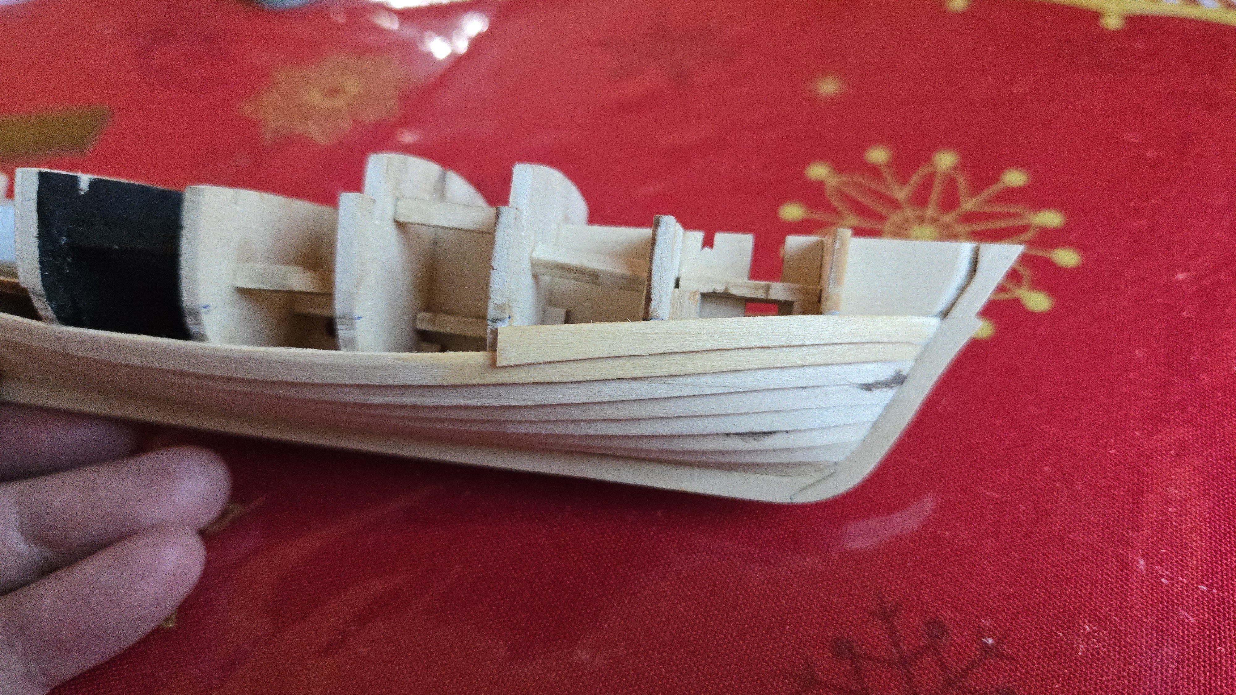
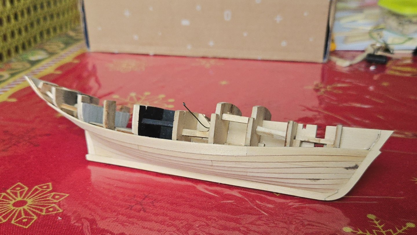
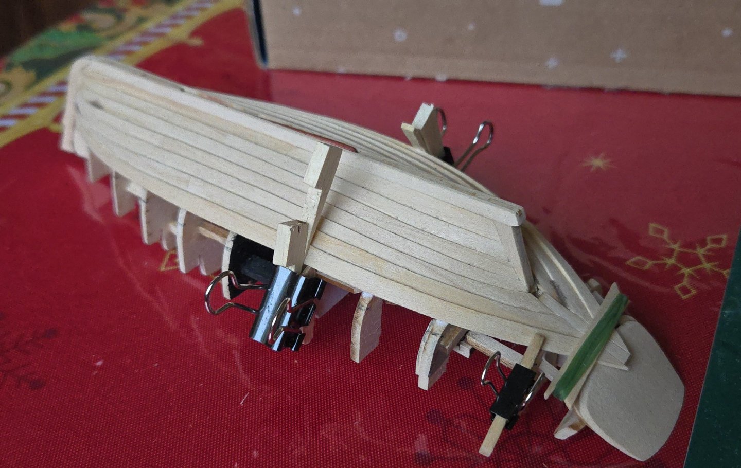
It's been a little while since my last post. During that time, I was pretty busy with work and travel. In fact, I'm still traveling! But, this model is small enough that I was able to pack it with me to advance a bit on the planking. The curves around the stern make clamping difficult, and as I'm going around the turn of the bilge, I've often needed to take care to make sure the bottom edge and not just the top edge of the plank is properly in contact. As can be seen, I've ended up using rubber bands and shims to hold things down. I had a bit of trouble with this bow plank, too, which I accidentally glued too low at its aft end. Fortunately I was able to unglue it and place it properly. At this point, I've finished the second of three bands. I now need to mark out the final band. I'll have to keep in mind that the sheer plank needs to extend 1/32-inch above the bulkhead tops (as I'll be planking the deck), and that I shouldn't glue anything to the bulkhead in the cockpit that will be removed later.

-
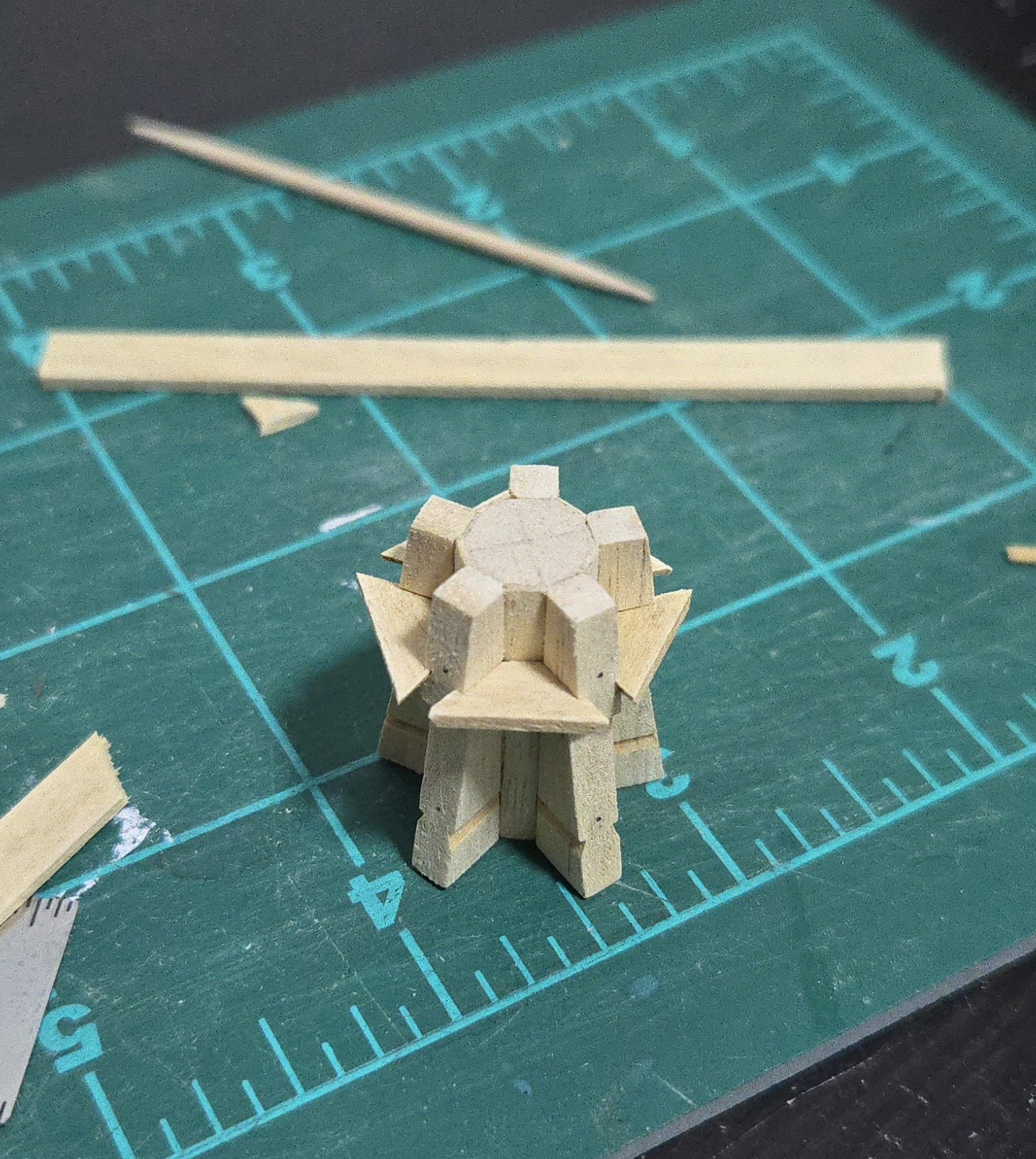
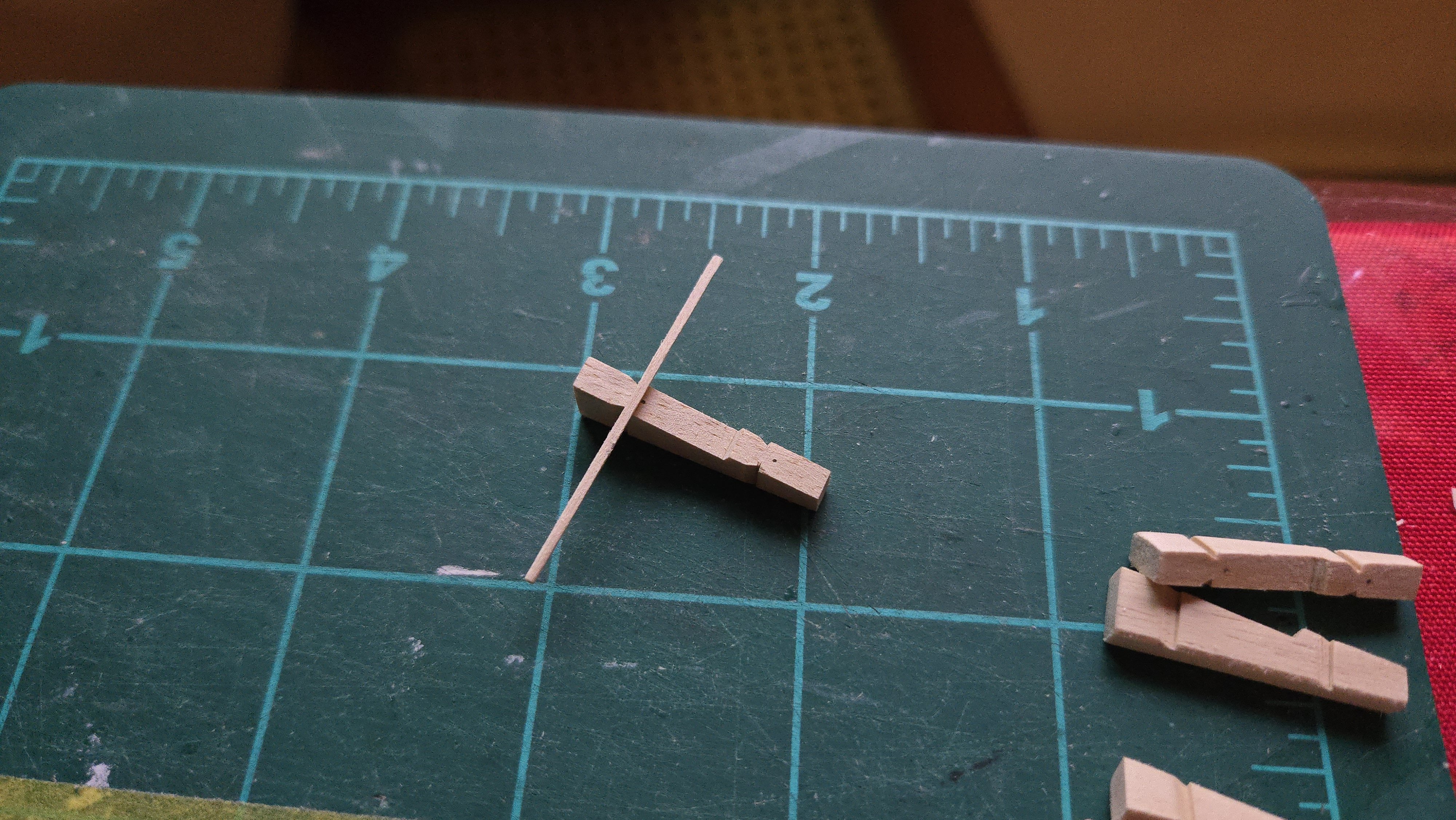
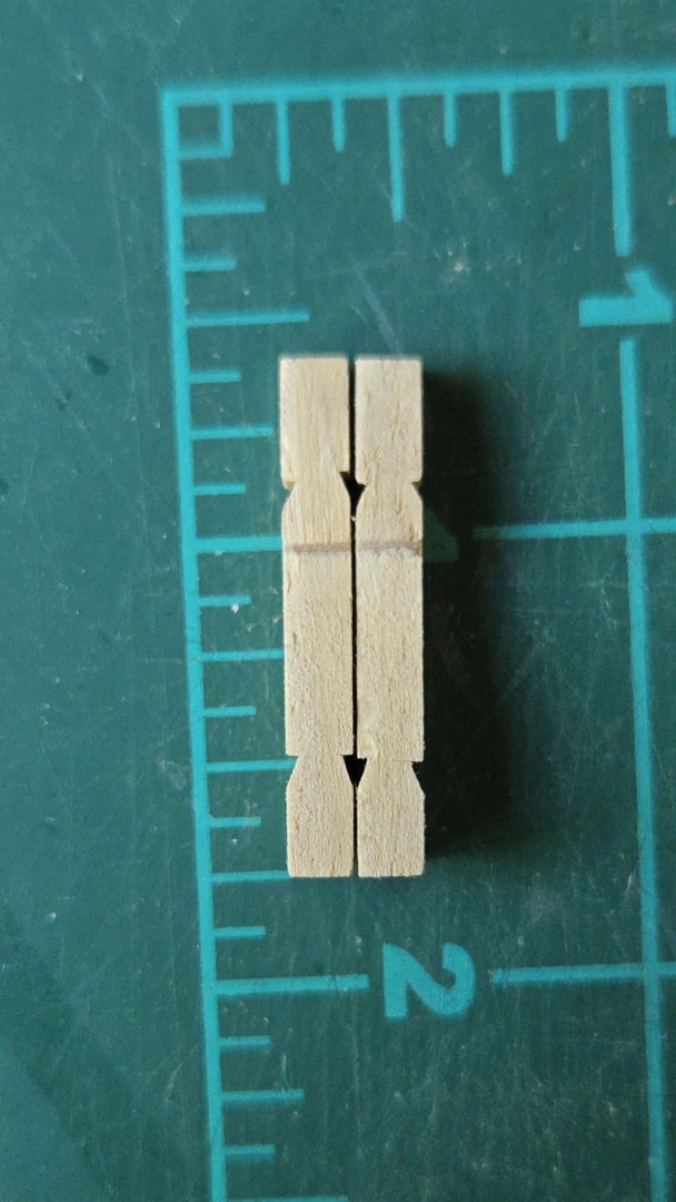
Thanks, all! It's much less precise than it appears. The next step was to even out the whelps and add the chock notches. To get everything even, I tack glued the whelps together and then sanded them. In the photo below, there are still a few sides to be sanded (notably the top and bottom). I then separated the whelps and sanded the slight bevel at their back end. Adding the chock notches was surprisingly tricky. Due to the bevel and the small size (just over an inch long), it was difficult to use my mini carpenter's square to cut perpendicular to the back. I screwed up on one notch, ruining a piece, as can be seen below--the slight unevenness between the lower notches can be easily finessed later, but the top notches are too far misaligned. Fortunately, I was able to make a new whelp fairly quickly. Going forward, I used existing whelps to mark the notch locations on the front and back, making them significantly more even. Finally, I marked out the spots where the bolts (or treenails?, I forget) are located. Given the small size, rather than trying to measure precisely, I just ran a spacer on top of the notches and eyeballed the center. I don't have my pin vise with me, so for now they're just marked. And with that, I have five whelps ready to go. Next up, to try to "mill" some very thin manzanillo and to work on the drumhead.


- 32 replies
-
- 11
-
-
- NRG Capstan
- NRG
- (and 1 more)
-
Very interesting! There are certainly some overlapping features, presumably driven by similar needs.
- 17 replies
-
- 1
-
-
- barco rabelo
- 1/75
- (and 2 more)
-
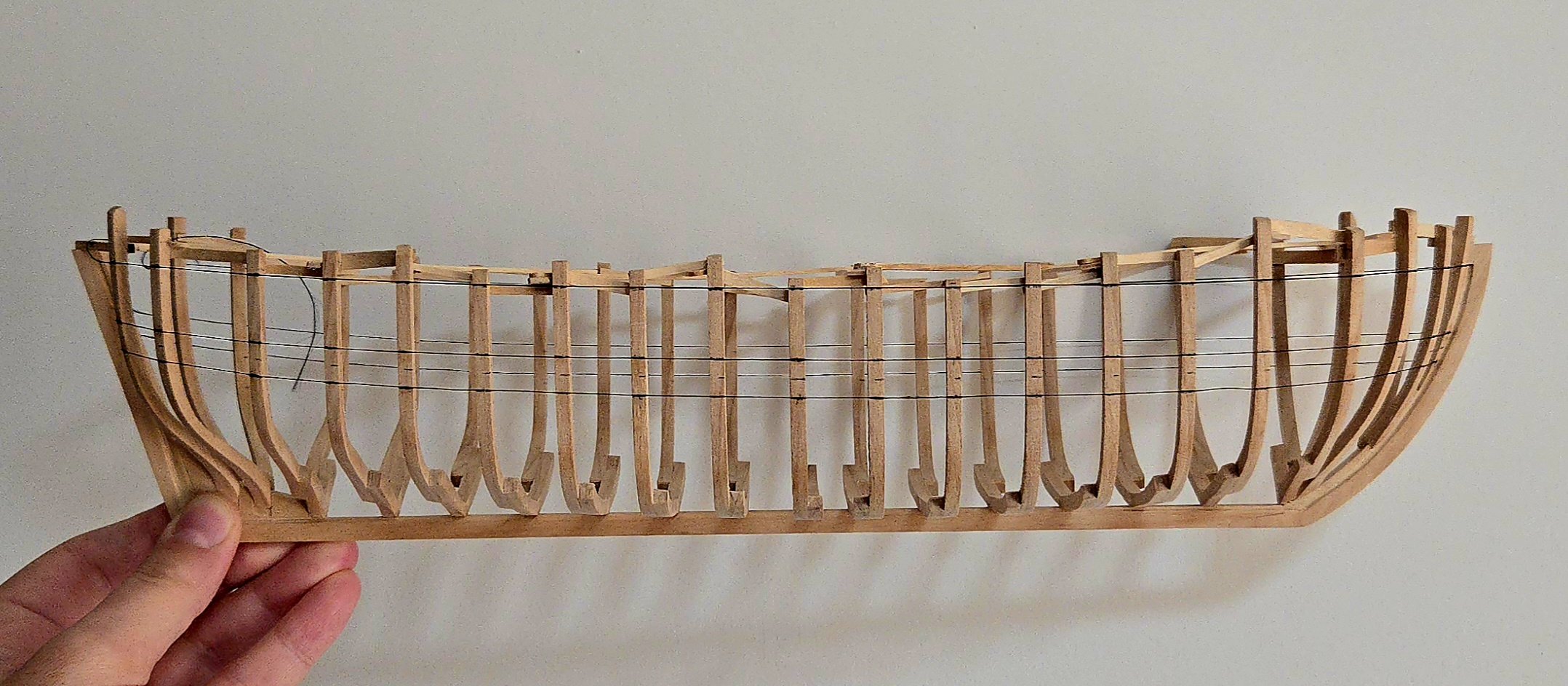
Amazing work! What thickness of wood are you using for the frames?
-
Nice work! The AI-generated rigging is interesting, it seems determined to stick a boom off the aft end of the pilot house. I think you'd have better luck looking for photos of fishing boats and checking if there are any build logs of similar vessels.
- 38 replies
-
- 3
-
-

-
- Fischkutter
- Laser Creation World
- (and 1 more)
-
Nice job!
-
Very nice kitbashing work!
-
Merry Christmas and Happy New Year!
-
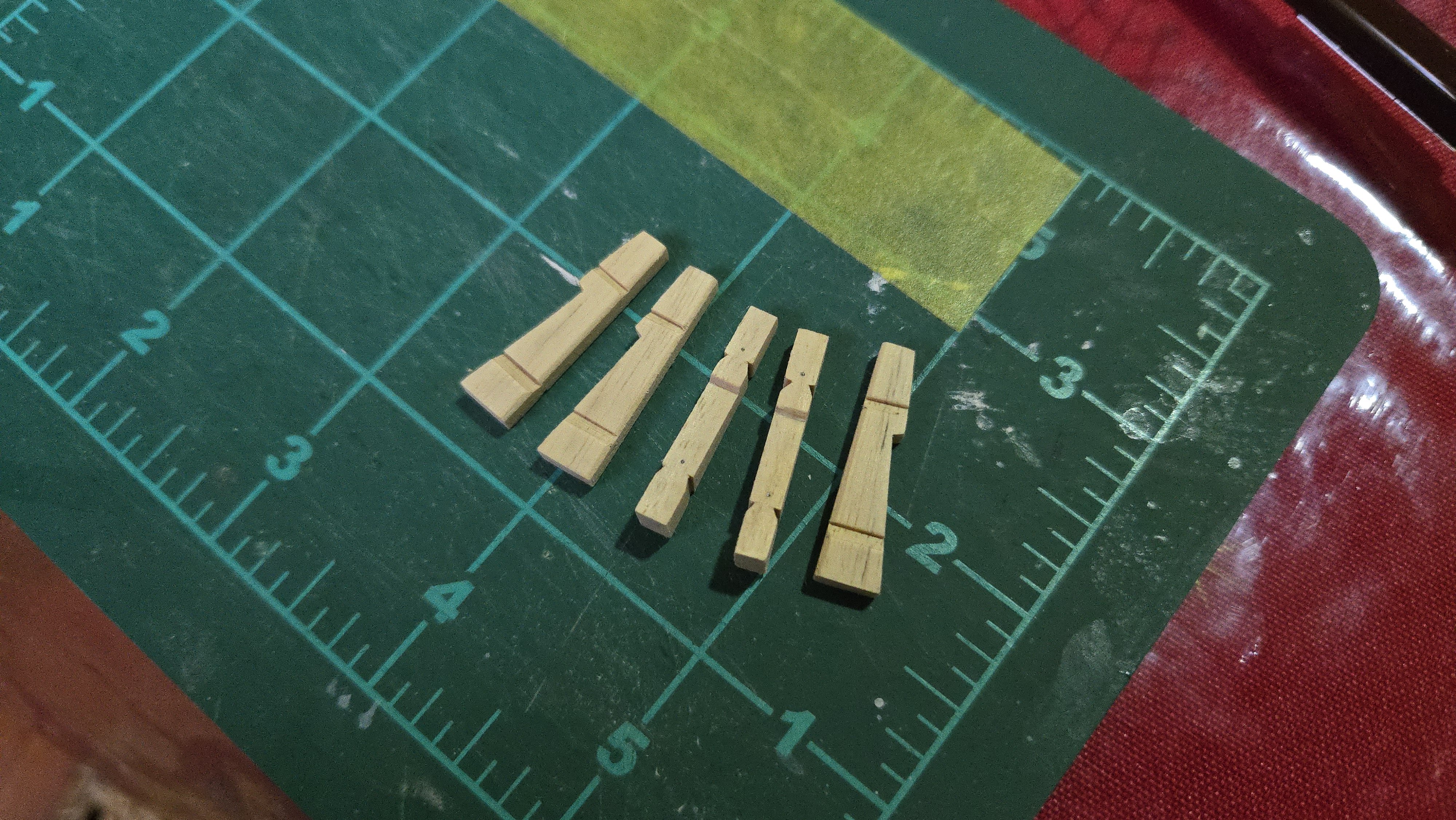
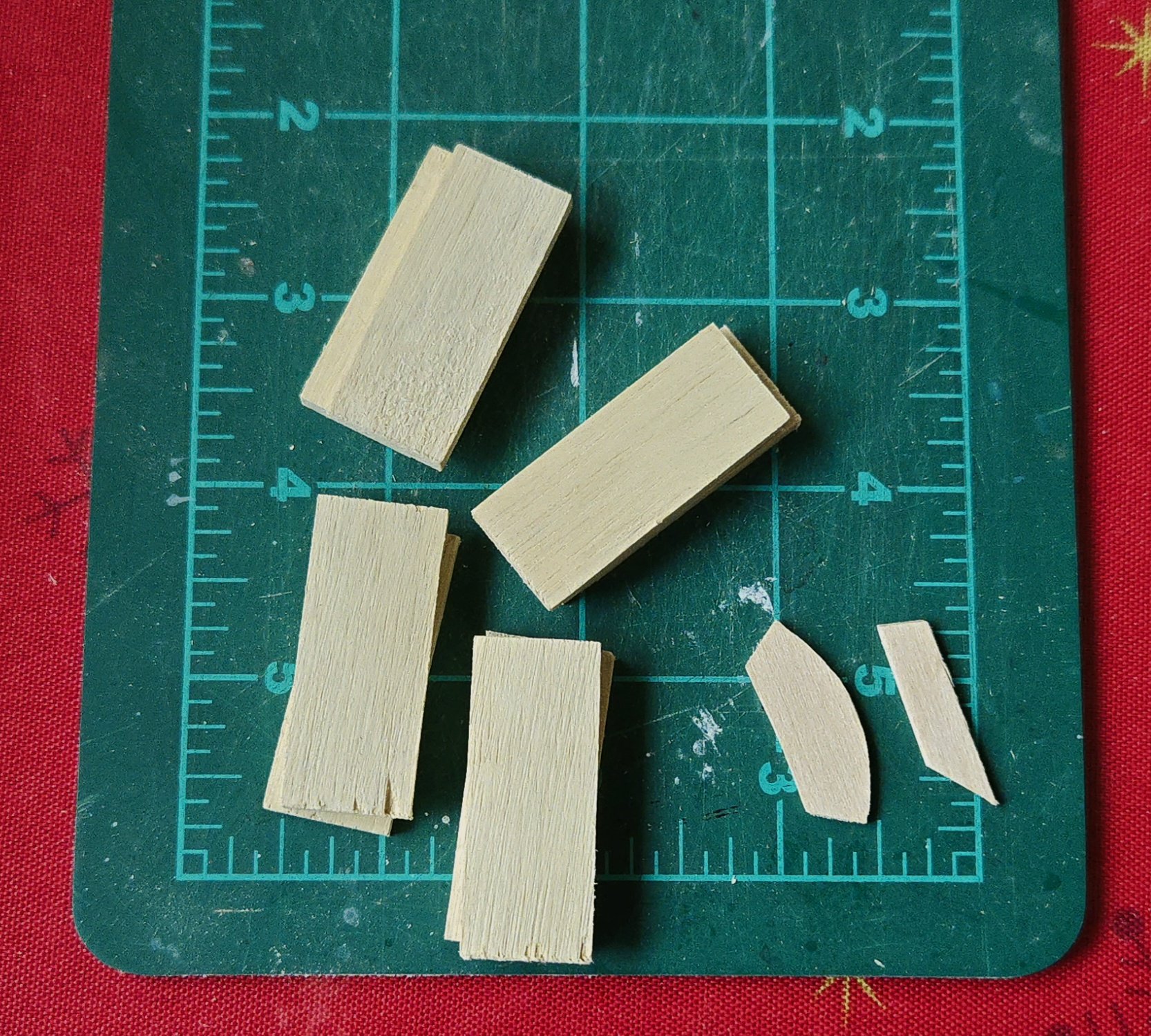
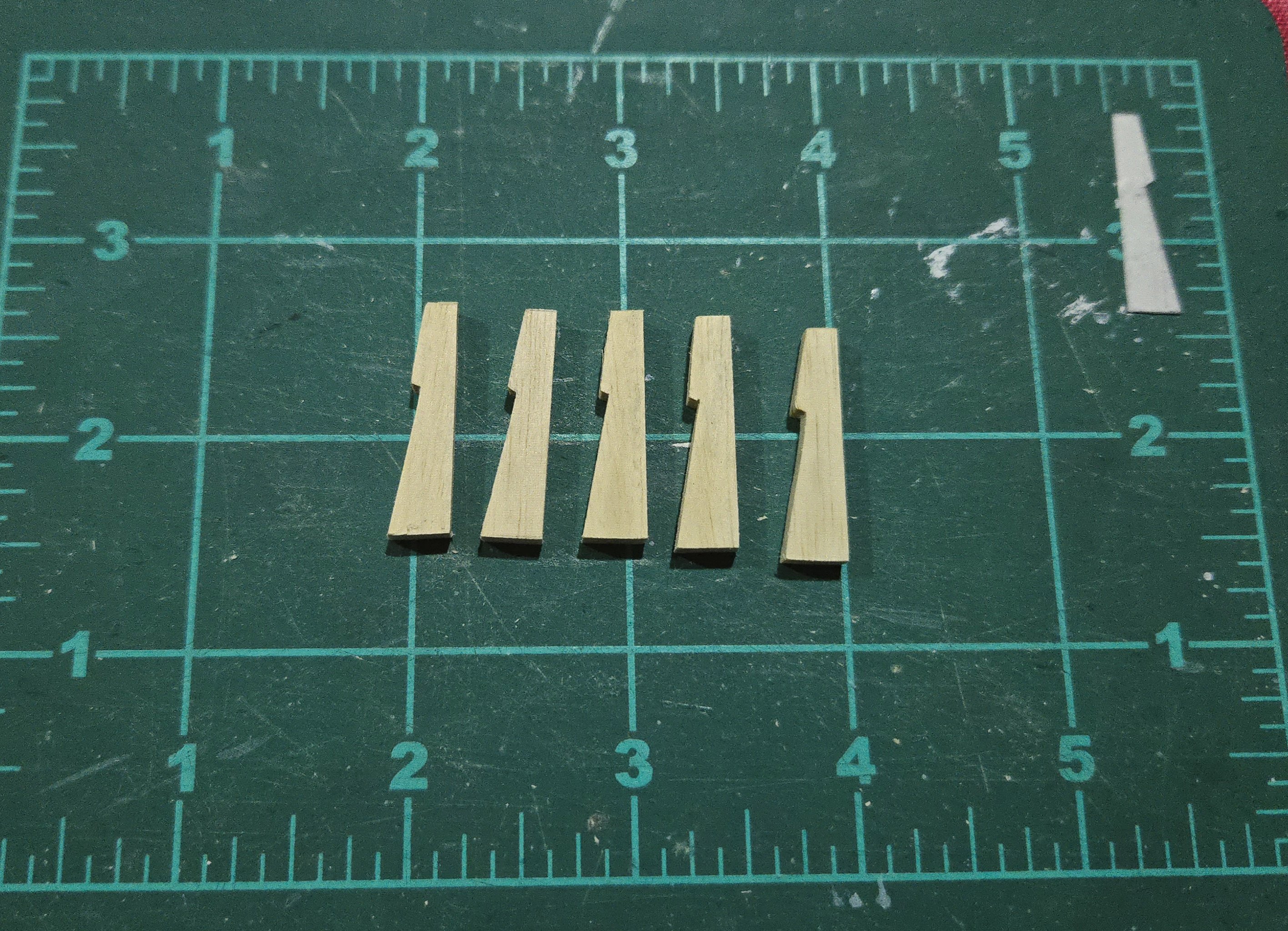
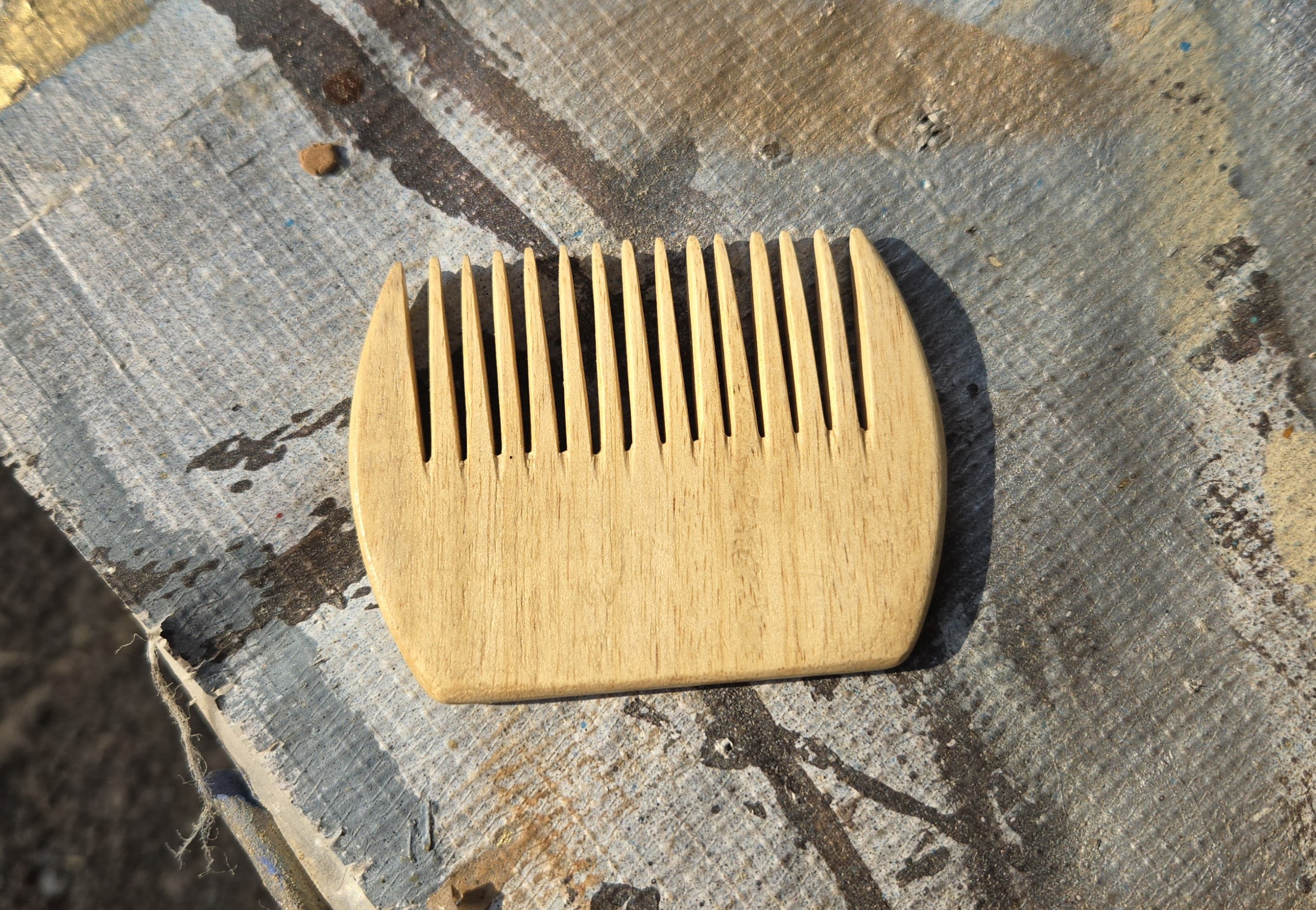
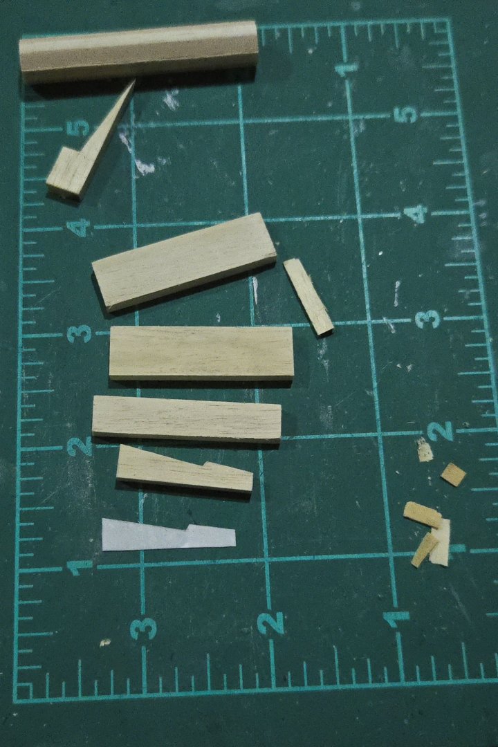
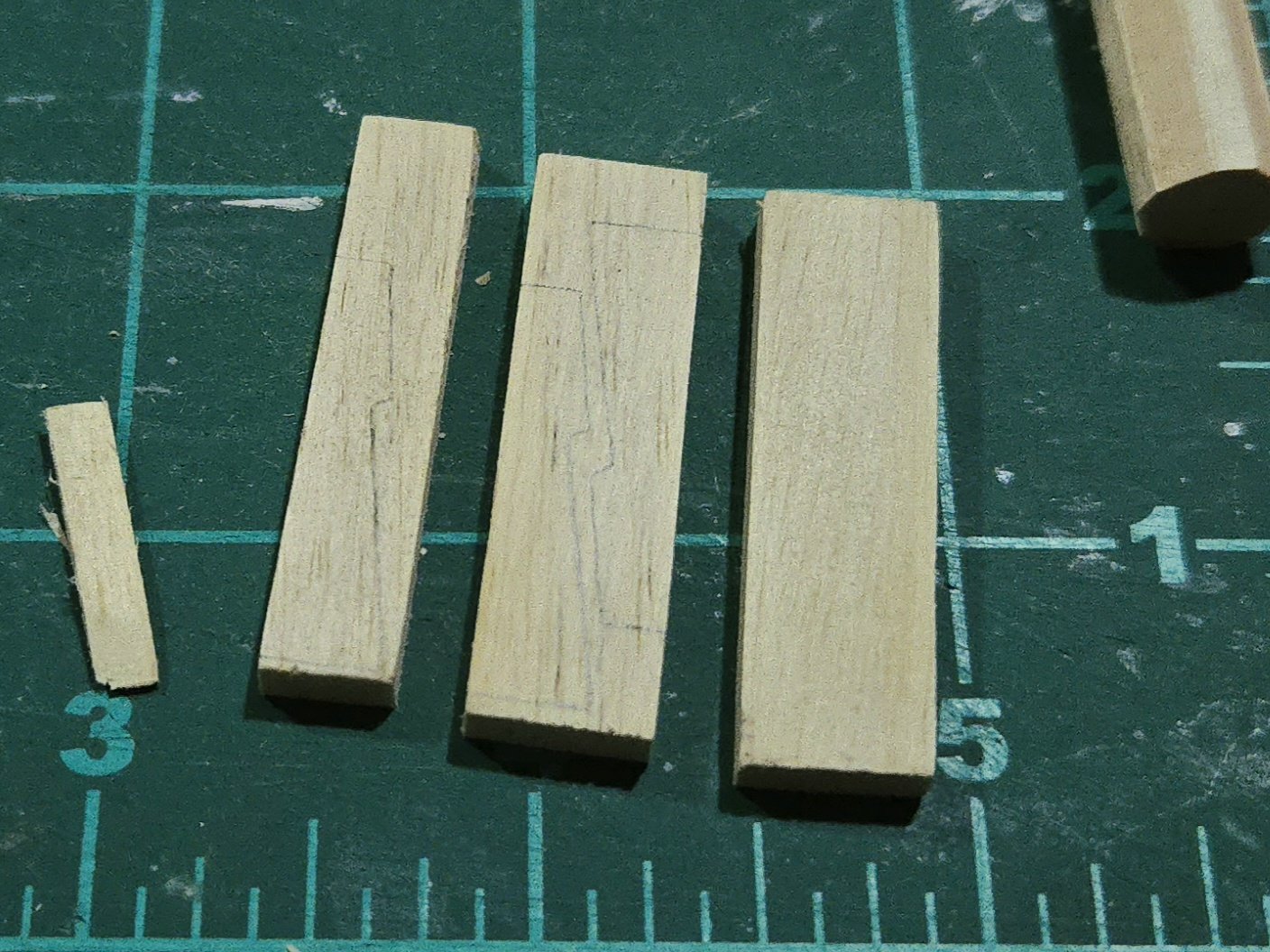
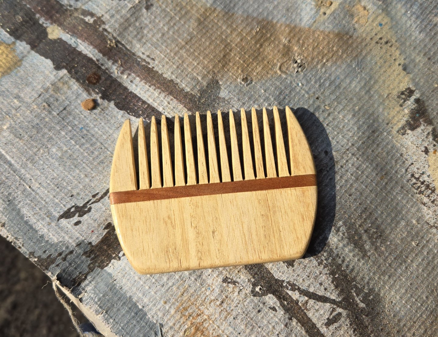
It's been a while since I last posted. I was able to make a bit of progress recently, though. As I mentioned earlier, I wanted to make the barrel out of manzanillo, which required hand "milling" some of the planks down to size and, more generally, learning about the wood's working qualities. As part of learning how to handle manzanillo, I made a comb from it as a Christmas gift, with a cherry accent strip (placed to cover up some uneven sawing on the teeth--I think it would look better further back on the handle) and finished with shellac. The comb was a real challenge to make, and there's plenty of things I would do differently if I made another one, but it was a helpful experience for figuring out how to work with manzanillo. The good news: the manzanillo hasn't caused any sort of reaction, allergic or otherwise, so I'm good to go with sanding and shaping it. It's a lot softer than I had initially realized, maybe close to basswood, but with somewhat more prominent grain. So, it may not be a fully ideal modeling wood, but I don't think it's a terrible option, especially if I'm looking for wood that's available here. Milling it from the 3/8- and 1/4-inch thick boards into useable sizes was challenging given my total lack of suitable milling equipment. Thankfully I don't need very large parts, so I was able to handle everything with a razor saw and a mini-block plane. (The scrap at bottom right in the photo below is basswood, the more yellowish color of the manzanillo stands out). Some of these will be used for thw barrel head, and others for the whelps. I made a card template for the whelps and stiffened it with superglue, and used that to draw the shape of the whelps. I was then able to cut them out. I'm currently traveling for the holidays, so instead of using a saw, I only have access to a hobby knife, but the manzanillo is soft enough that I was able to cut it. Soon I had all five whelps: They need a bit of final shaping for consistency, the bevels added at the back end, and the notches for the chocks carved out. I'm not looking forward to trying to thin the manzanillo down to 1/16 and 1/32‐inch thick parts for the chocks, but I think it will look more consistent than taking the easy way out and using basswood.


- 32 replies
-
- 11
-
-
- NRG Capstan
- NRG
- (and 1 more)
-
Looks like you're off to a great start! Very cool to be able to model something you have a personal connection with. Wye River seems to make some very interesting models.
-
Looks good to me! I feel like with a bit of filler and sanding it should smooth out nicely. Challenges with the sheer strake aside, the kit planks seem to go together very nicely. I almost regret going with lapstrake planking on mine, as it has made what I was hoping would be a straightforward, fairly simple build into something rather more complex. As for the more prominent grain on the sheer strake, I wonder if a bit of shellac or some other sort of sanding sealer would smooth it out? (I seem to remember that you're planning on painting this hull, I could be wrong though). I recently tried shellac for the first time on a different project and was pleasantly surprised by how smooth it turned out and how straightforward it was to apply, and apparently it takes paint very well.
-
Thanks! There's certainly some variety, I wonder to what extent that comes down to different boatbuilders having different ways of doing things. A higher stern than bow seems a constant.
- 139 replies
-
- 5
-
-
- ancre
- Bateau de Lanveoc
- (and 2 more)
-
Thanks, Waldemar! That's certainly much more sheer than the monograph drawings. After a lot of consideration, I decided to adjust the sheer line slightly in order to get a little bit more of a curve than in the monograph drawings, but not quite as much as in the Pâris plan. It's a small adjustment, a matter of a millimeter or so amidships, but I think it looks better without deviating too drastically from the monograph plans. Of course, the photo is barely distinguishable from the previous photos... I've now marked out the wales and sheerline. I'll next need to remove the thread, lightly sand the fore abd aft sides of the frames, and then begin planking.

- 139 replies
-
- 7
-
-
- ancre
- Bateau de Lanveoc
- (and 2 more)
-
Very nice work! That Brazilian pine looks great. I wonder how many of Luisito's furnishings and fittings were scavenged from the shipwreck, which could result in some seemingly oversized equipment for a small vessel.