JacquesCousteau
-
Posts
1,374 -
Joined
-
Last visited
Content Type
Profiles
Forums
Gallery
Events
Everything posted by JacquesCousteau
-
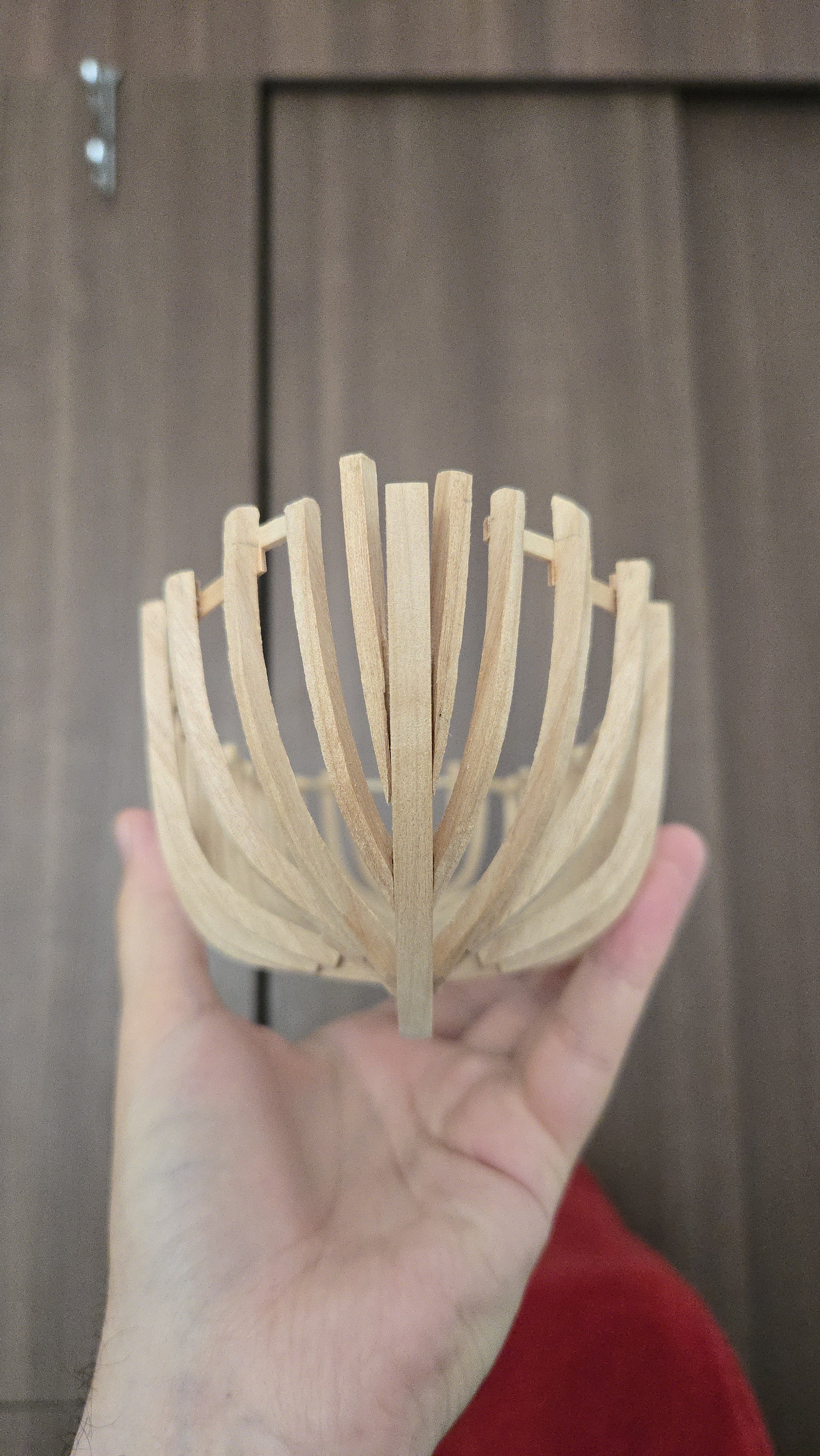
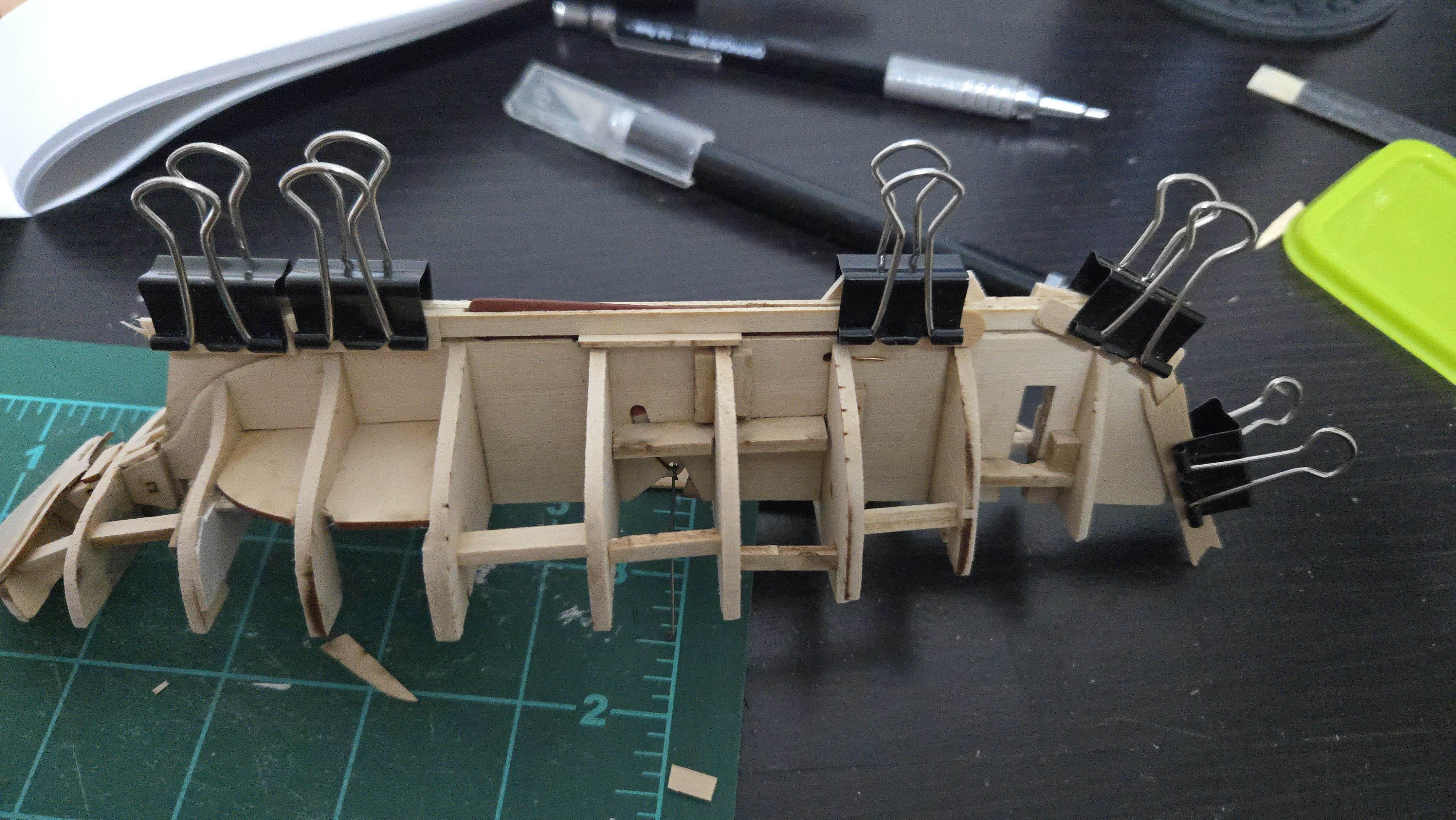
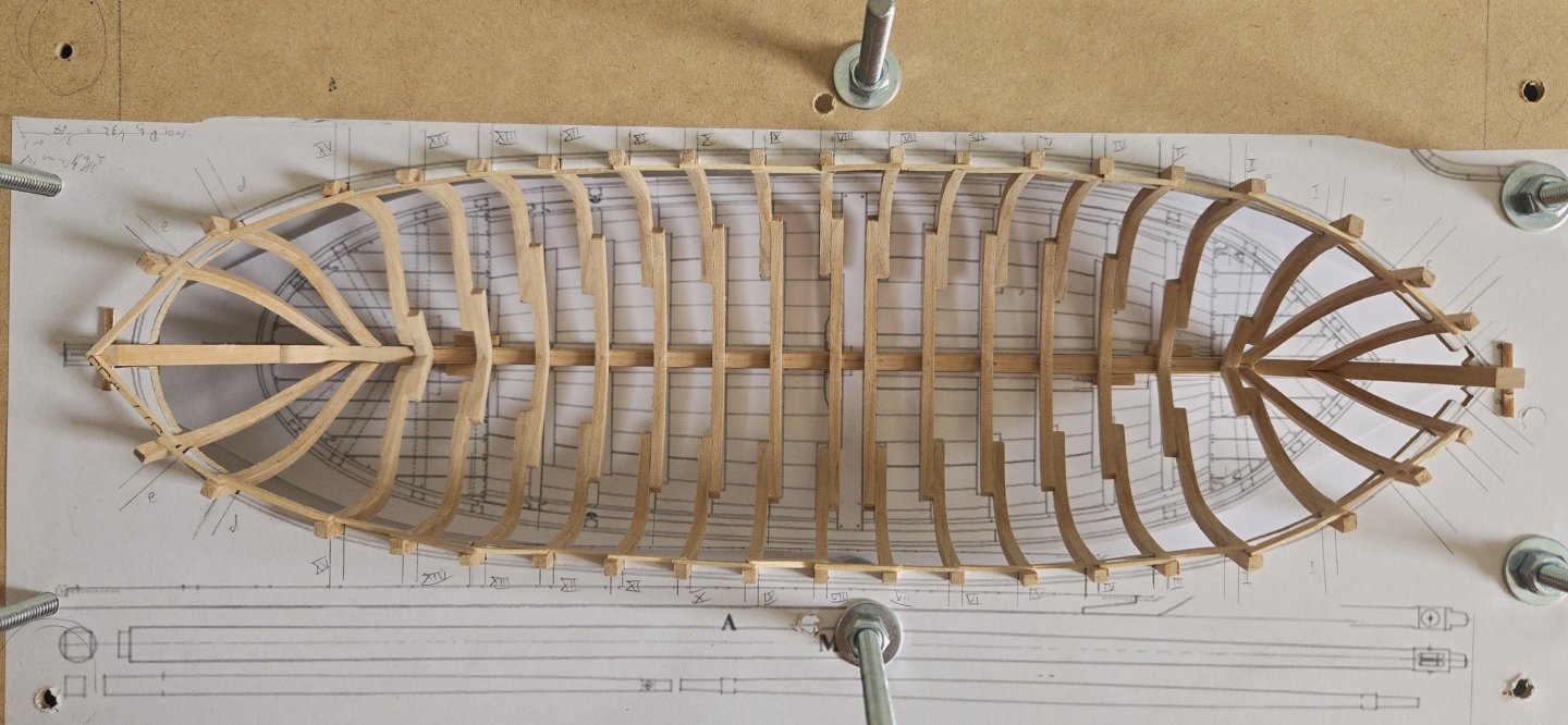
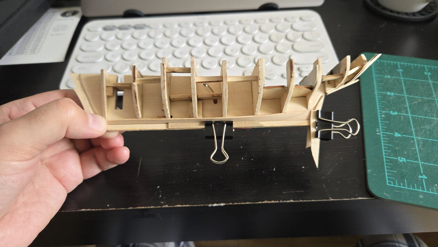
 Thanks, all! @tkay11, I knew one of those dimensions had to be molded and one sided, but I wasn't sure which, so thank you very much for clarifying! I decided to go ahead with fairing. If the frame needs to be redone in the end, there's no harm in trying to fair it into shape first. I tend to fair pretty slowly over the course of days if not weeks, both because it's tedious work, and because taking my time makes me less likely to take too much off and more likely to really get things right instead of deciding that it's close enough. I noticed that the hull was quite flexible, so I added a bunch of supports across the top. They're as haphazard and ugly as the supports between frames, but thanks to the power of triangles, the hull is now pretty resistant to flexing and twisting.
- 139 replies
-
- 8
-

-

-
- ancre
- Bateau de Lanveoc
- (and 2 more)
-
Amazing work! It's incredible how realistic it looks at such a tiny scale.
- 457 replies
-
- 3
-

-
-
- sternwheeler
- Hard Coal Navy
- (and 1 more)
-
I can't speak to what would make more money (from what I understand, model making is quite a tricky endeavor to make profitable). But as for paint vs natural finish, it's really a matter of style. Most workboats would have been painted or otherwise at least partially covered with some sort of material, like tar, as a protective measure. So if your goal is to make an accurate representation of what one of these vessels looked like, paint would be necessary. But modelers frequently avoid straight realism for something more stylized--think, for instance, of the many models out there with exposed framing. Highlighting the natural colors of the wood is a stylistic choice that can be quite nice. All of which is to say, painting isn't just to cover mistakes, but whether to paint or not is a stylistic decision for you to make based on what you're going for.
-
Thanks, Waldemar, for the suggestion! I started writing my earlier post before you posted this, so I didn't see it until now. That would definitely work for the external side of the frame, but that's the part that's been giving me the least trouble. The cant frame is so close to the stem that its alignment with the rabbet is pretty easy to eyeball. The joint with the stem is the part that's really been giving me trouble. Although I suppose a series of battens along the exterior would reduce the amount of play in test-fitting the joint. I'll keep this in mind if I decide to redo those cant frames. I'd like to have them in place before planking as otherwise there's very little gluing surface at the stem.
- 139 replies
-
- 3
-
-
- ancre
- Bateau de Lanveoc
- (and 2 more)
-
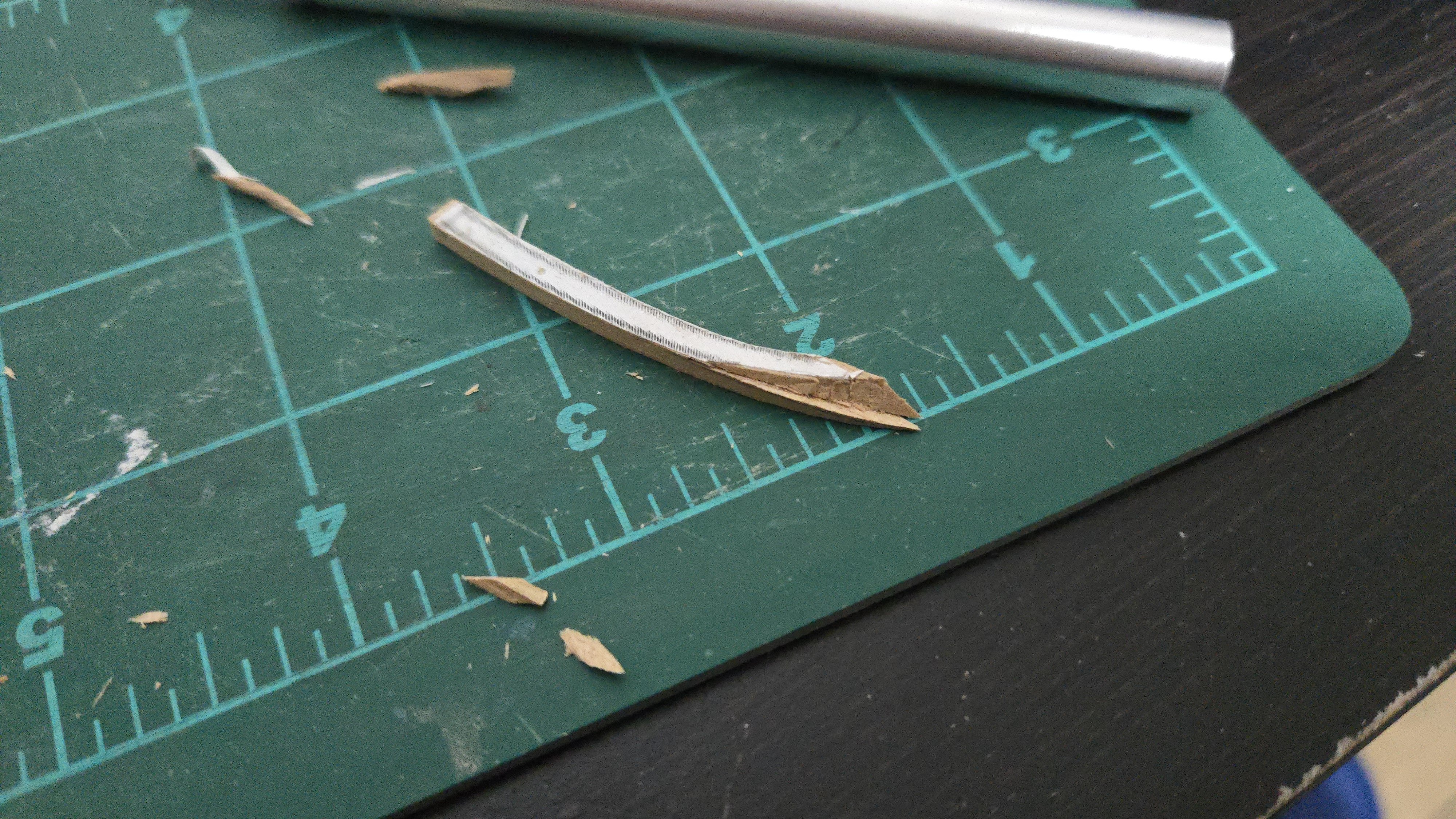
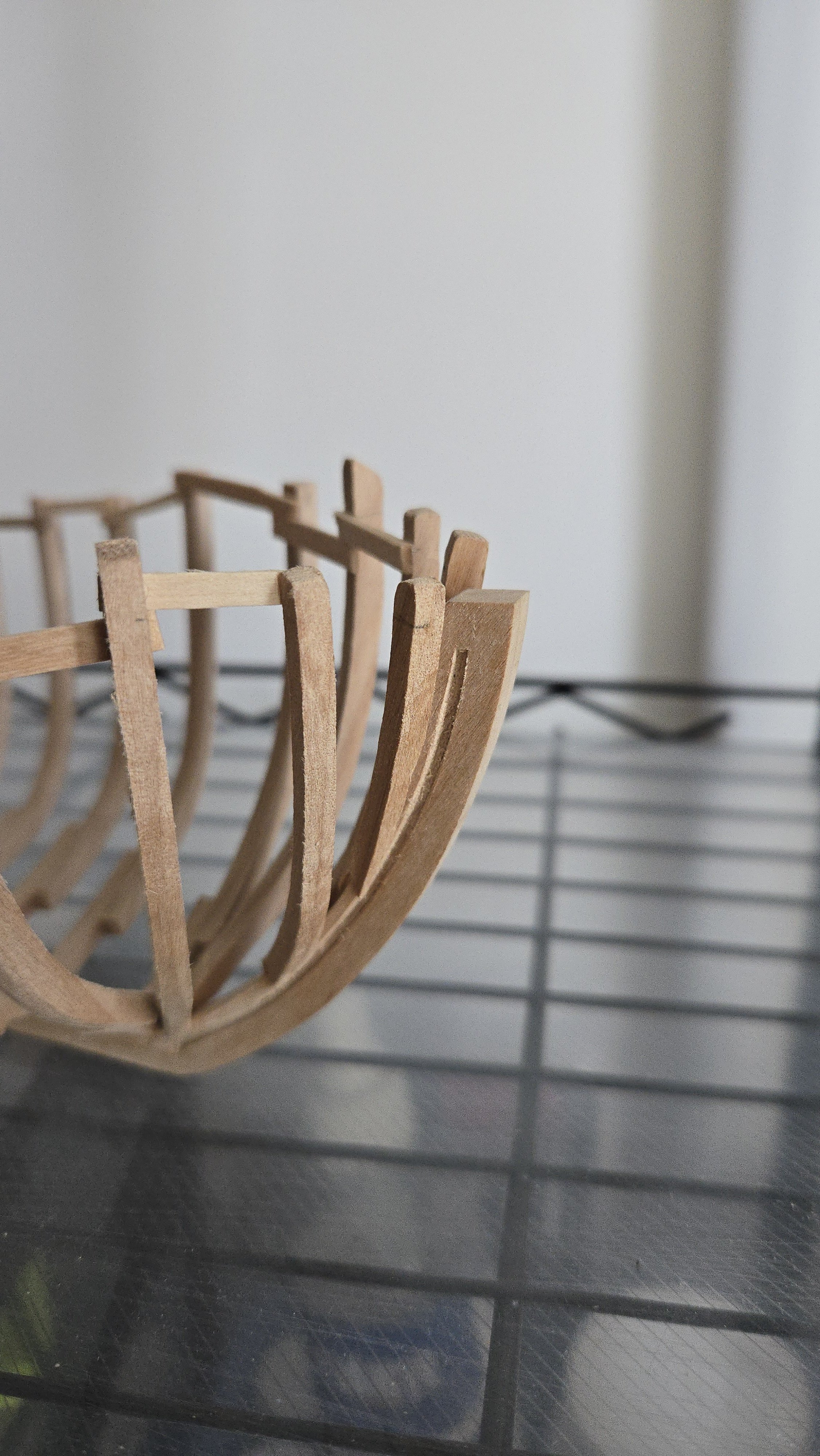
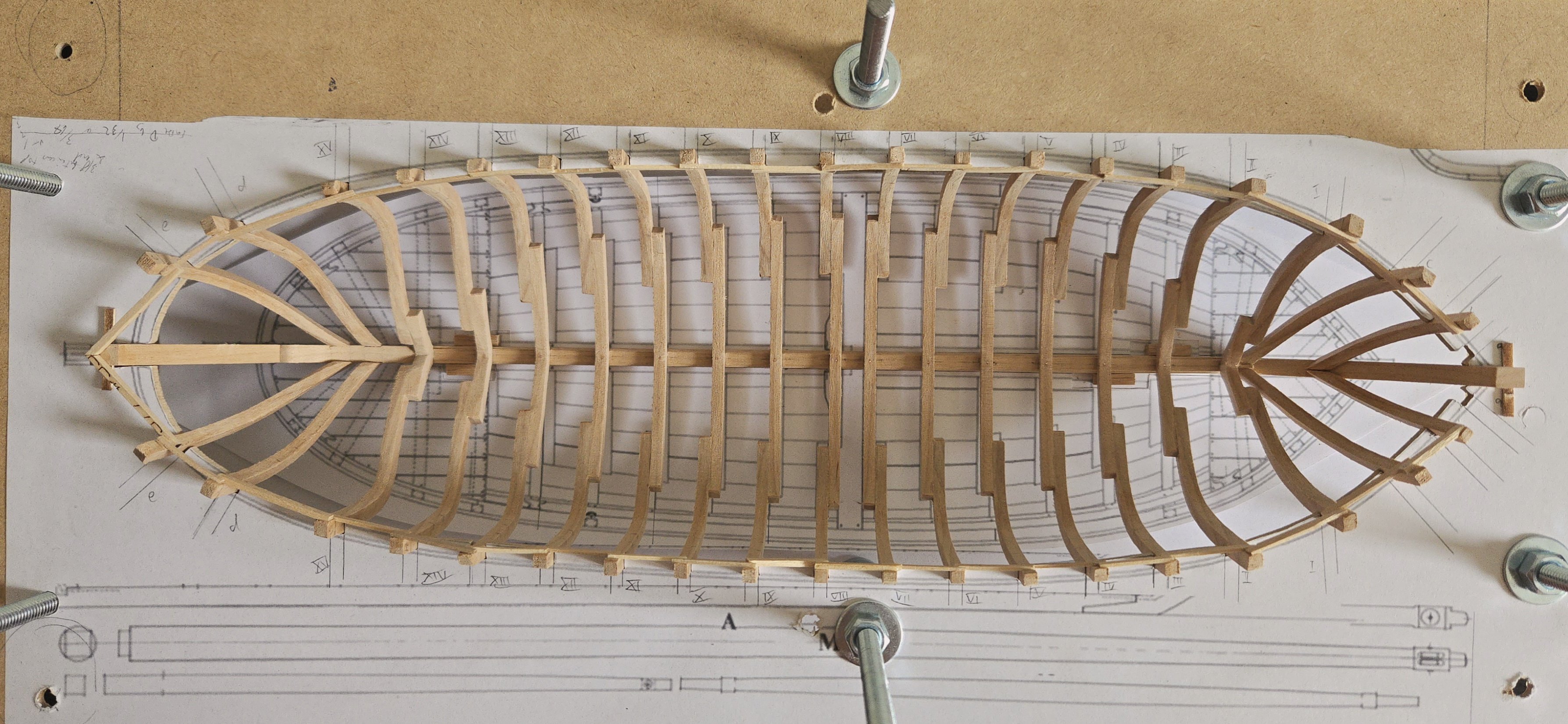
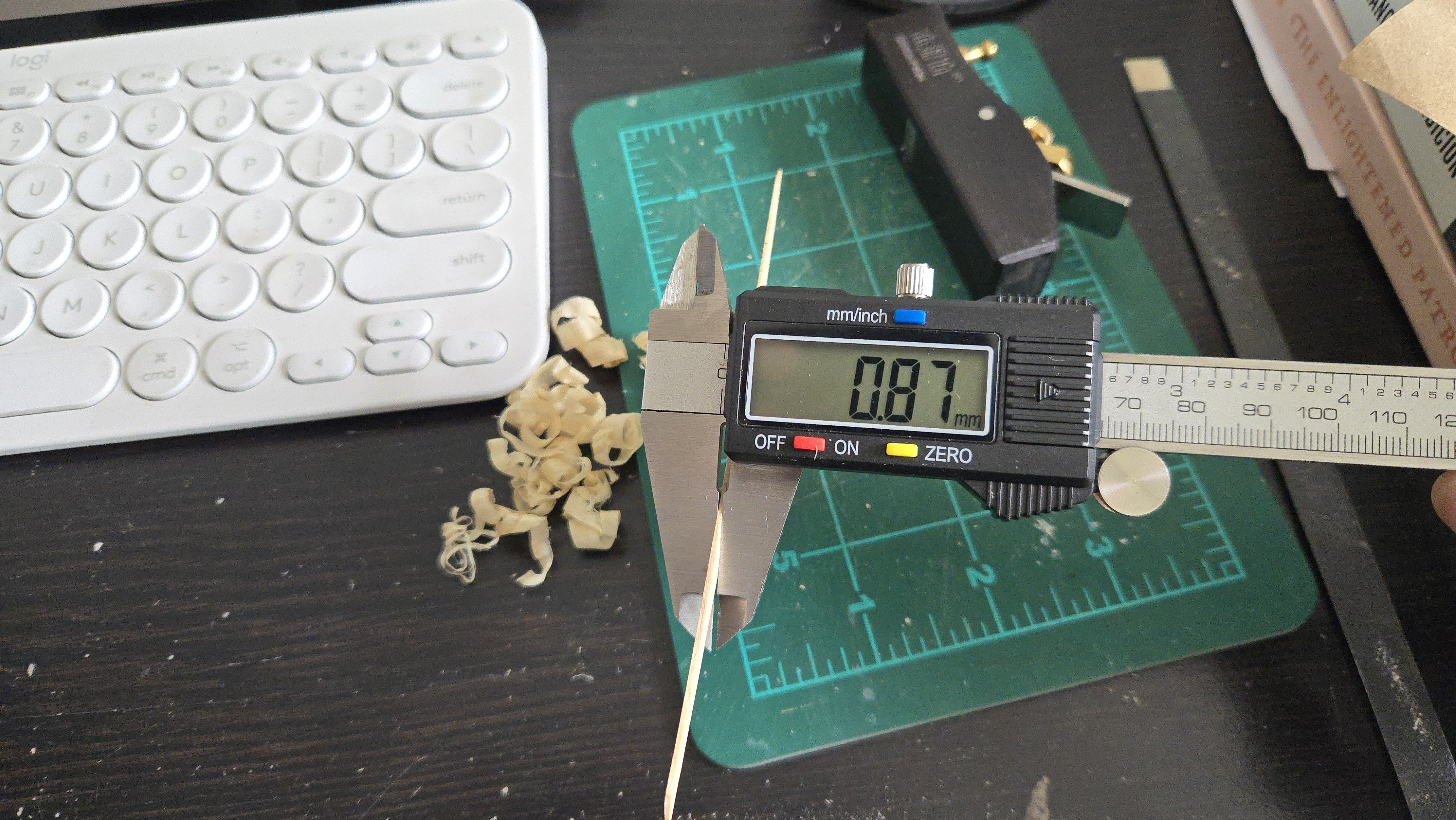
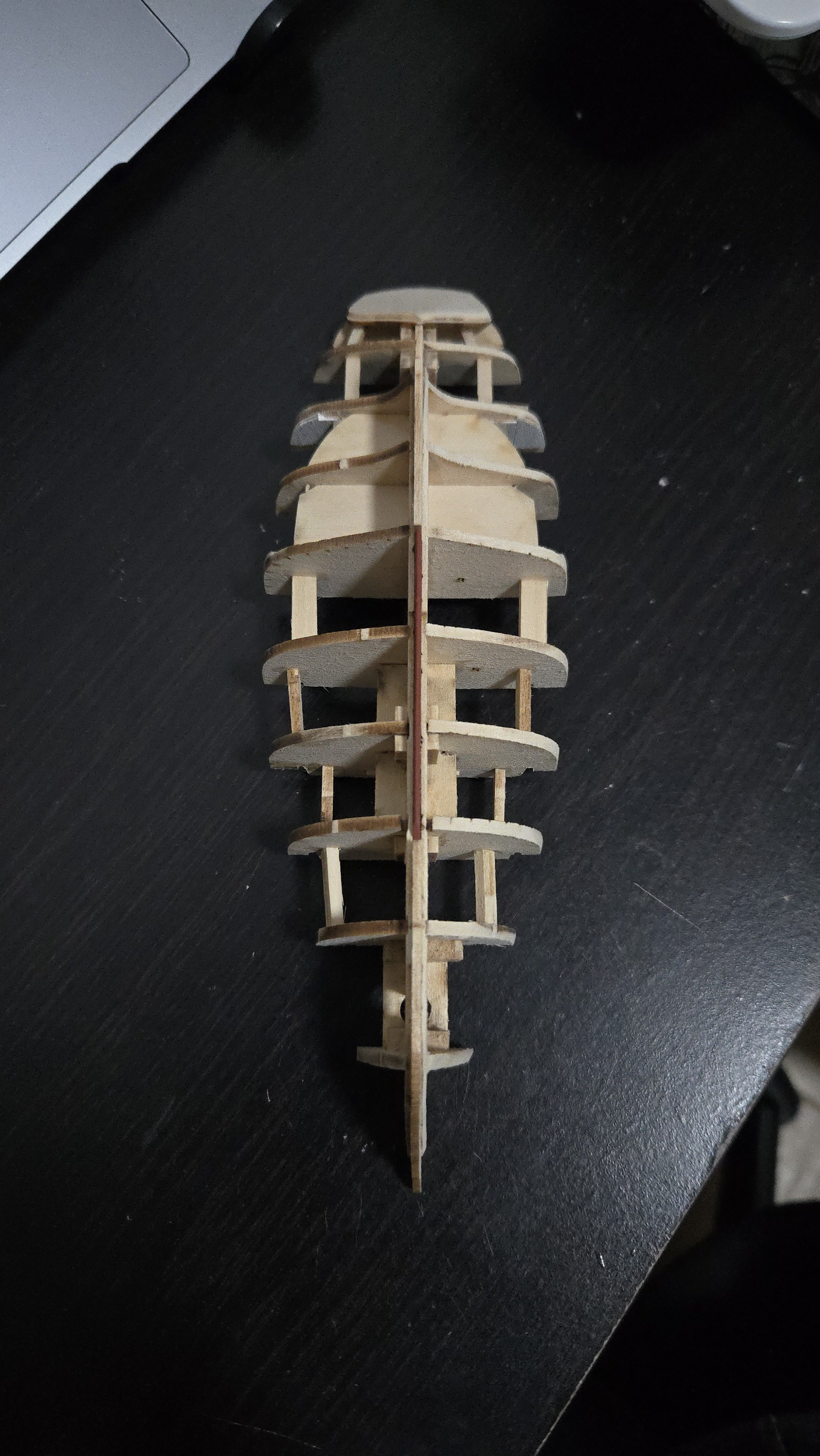
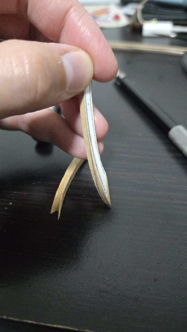
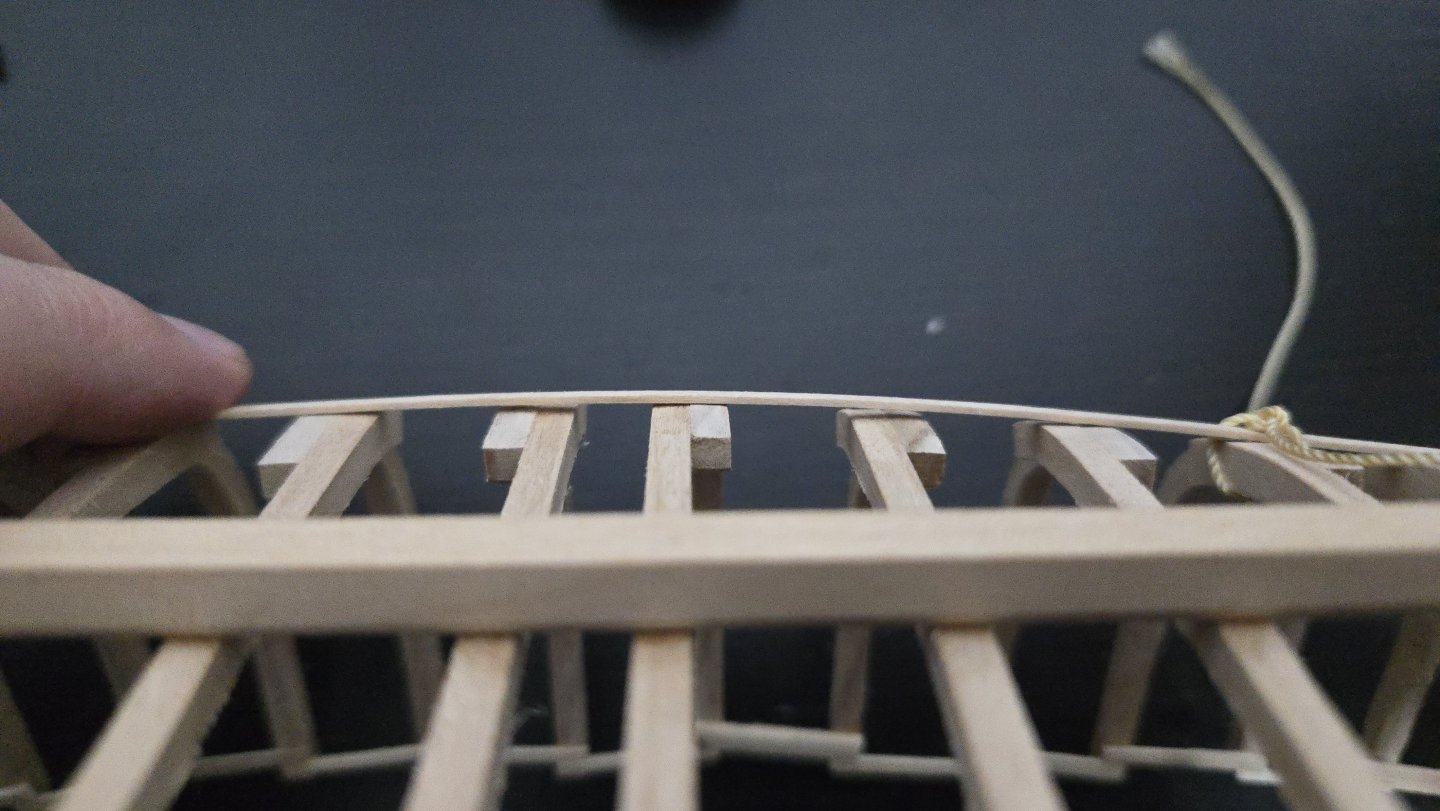
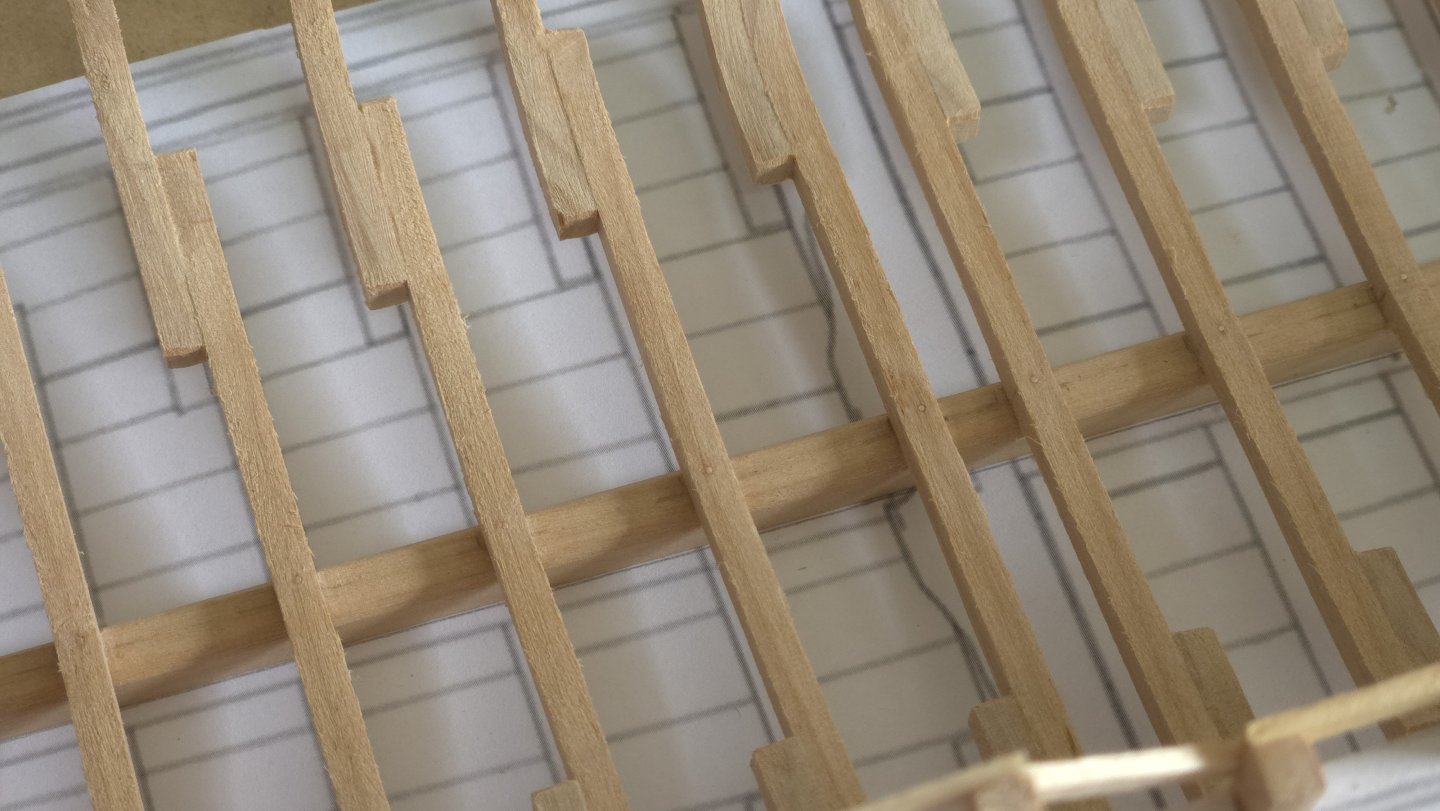
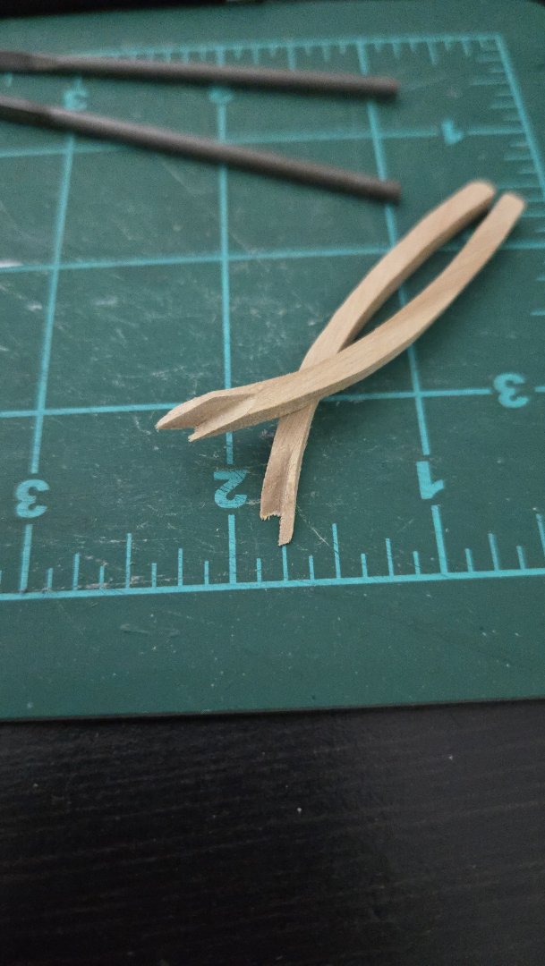
That's a very intriguing suggestion, thanks! I think I would have to pre-shape the notch to some degree before fitting it to the stem, as there would be a lot of excess material distorting things if I just squished an unnotched frame against the stem. I haven't seen such clay but haven't been looking, I'll have to keep an eye out next time I'm in an art supply store. I ended up removing the starboard cant frame and cutting a replacement one from some scrap with a knife. Shaping it was a slow process, trying to adjust everything so it would fit better than the first one. I realized that the line of the cut across the outer face (which should join the stem) needed to be a curved line that, when the piece was positioned as it would be on the model, would appear straight when viewed from ahead (as can be kind of seen below). After a lot of slow, careful shaping and fitting, I ended up with a piece that looks very slightly better than the original. I think I can live with it, it more or less matches the port cant frame at least (minus some chipping that occurred). If the cant frames are tricky but ultimately maybe liveable, I've found another issue that may require a frame replacement, but I'm curious what others think. Running a batten along the hull, I'm generally very happy with how fair things are at this point. Without any external fairing, things are lining up pretty well (although the stern will be quite a pain in the neck to plank), much more so than on the plank and bulkhead models I've made so far. There's one part, though, that's not fair. As can be seen below, frame 8 seems to stick out quite a bit around the turn of the bilge, enough so that a 1/32‐inch/0.8mm strip can be slid between the batten and the frame to the right of it. There's a similar, though less extreme, problem on the other side of the frame. Would this be considered a big enough deviation from fair that I should try to remake the frame? It may be possible to just redo the floor, perhaps adding a tiny bit more height where it meets the keel so as to raise the turn of the bilge by a hair, and keep the original futtocks. (Although if so, I wish I had noticed this before I pinned the floor in place!) If I don't replace it, I think I would have to remove about 1/32 of an inch from the exterior of the hull here, and sand down the interior of the other frames by a similar amount to fair the interior. Looking at the monograph, I found the following about frame dimensions on page 41: "La membrure est compossée d'allonges ayant 88 [mm] d'épaisseur sur le tour et 122 de largeur sur le droit." Which google translates as: "The frame is made up of extensions having a thickness of 88 [mm] on the circumference and a width of 122 on the right." So I think the 122 is referring to the dimension of the frames from fore face to aft face, the frames are supposed to be 88mm thick (from exterior to interior side), at full scale, which translates to 2.75mm at 1/32‐scale. This comports with the frame drawings. My frames, including frame 8, are about 3.75-4mm thick right now depending on where they're measured. This suggests I could theoretically remove the 0.8mm or so needed to fair the exterior without dropping below the thickness given in the plans. So, replace or fair it out? If the former, I'd have to be careful to slightly adjust the floor from the drawings in order to not repeat the issue. If the latter, it does sound like a lot of sanding, but I suppose I need to do a lot of sanding anyway given that I cut the frames a bit wide of the plans. Any suggestions are welcome!


- 139 replies
-
- 9
-
-
- ancre
- Bateau de Lanveoc
- (and 2 more)
-
Thanks, Bryan, your shallop build looks great! For the most part, going the POF scratch-build route has been a lot of fun. Cutting out all the frames was more tedious than difficult, and I don't think it's beyond the skill of anyone with a bit of experience and lots of patience. The cant frames have really been by far the most challenging part of this, though, and here the problem is at least in part just due to a lack of clear info in the plan set about what to do. Something like David Antscherl's Hayling Hoy monograph seems from the build logs I've seen to have clearer directions (although it's also a much more complex vessel). That said, I have yet to fair and plank this hull, and it's entirely possible that I'll find that I screwed up in a major way on the frames due to a lack of precision somewhere.
- 139 replies
-
- 5
-
-
- ancre
- Bateau de Lanveoc
- (and 2 more)
-
Very nice work! On the sheet, is it just temporarily double-looped through the blocks, or is it supposed to use double blocks?
- 38 replies
-
- 2
-

-
-
- 18th Century Longboat
- Model Shipways
- (and 1 more)
-
Thanks for the suggestion, that would probably be the easiest way to get things. Yeah, hats off to anyone who can conceptualize these complex shapes intuitively (or through long experience). I suppose I could simplify it by not running the frames over the back of the stem and just cutting them at the right angle to butt-joint against the sides of the stem.
- 139 replies
-
- 5
-
-
- ancre
- Bateau de Lanveoc
- (and 2 more)
-
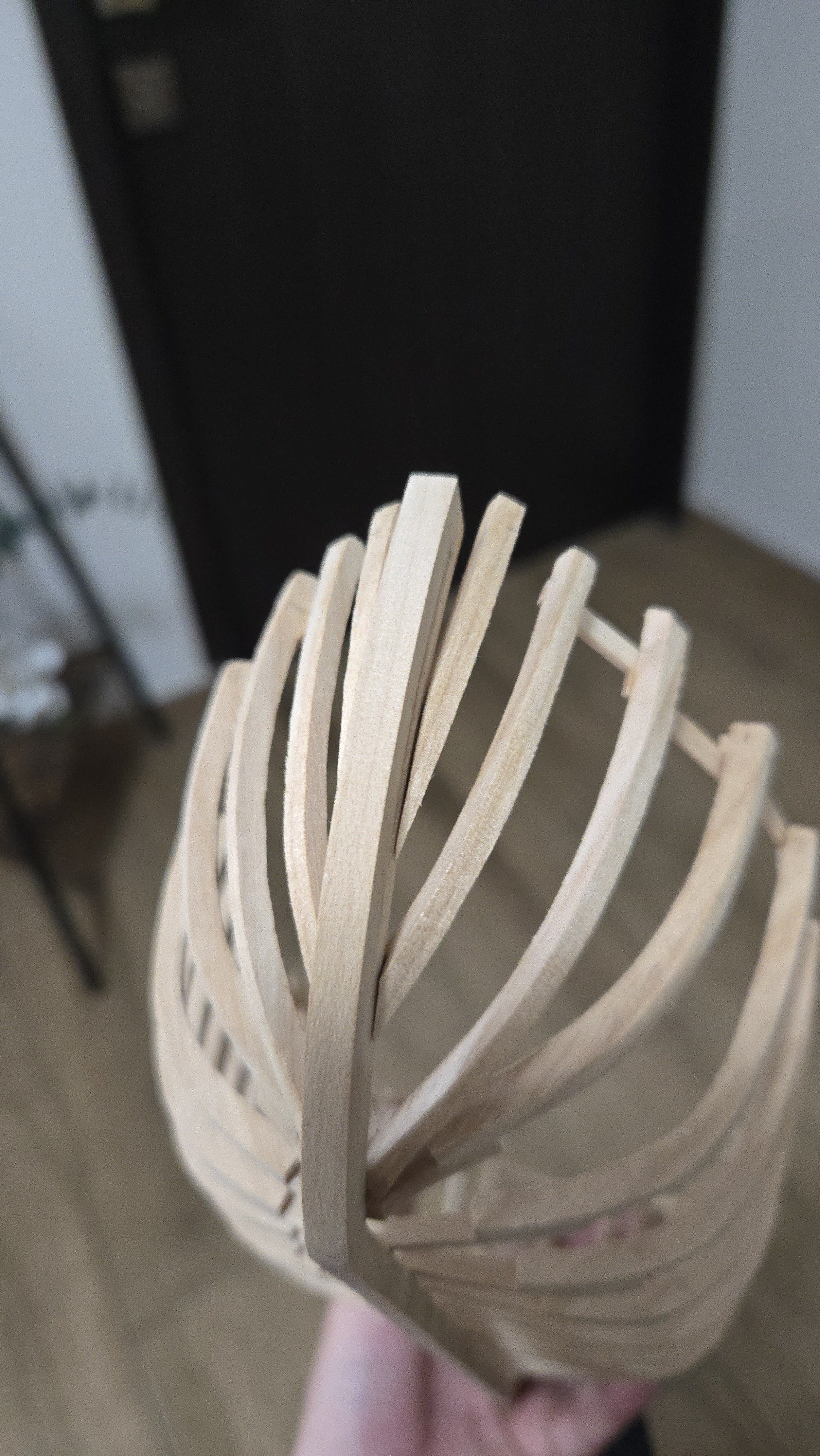
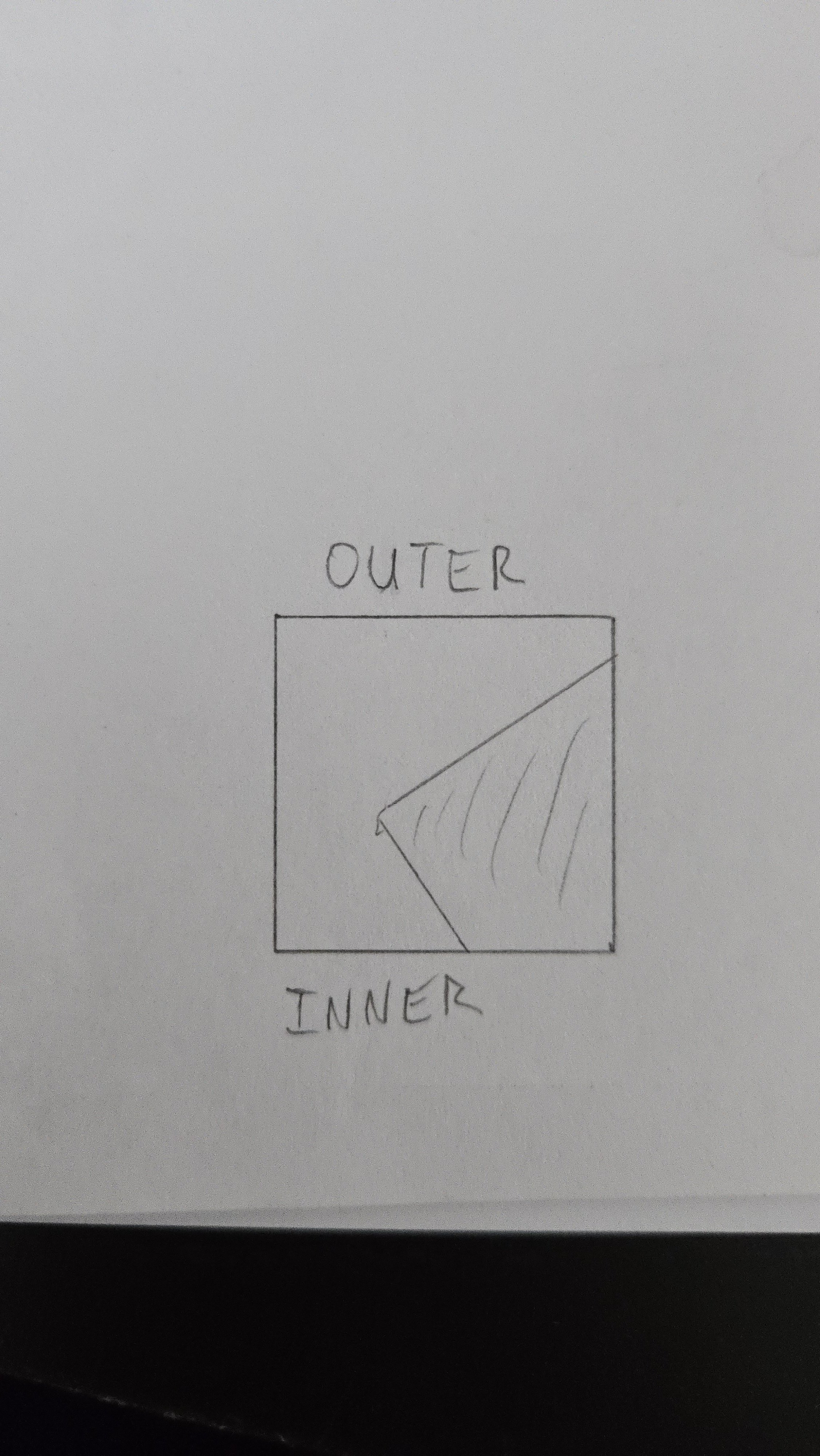
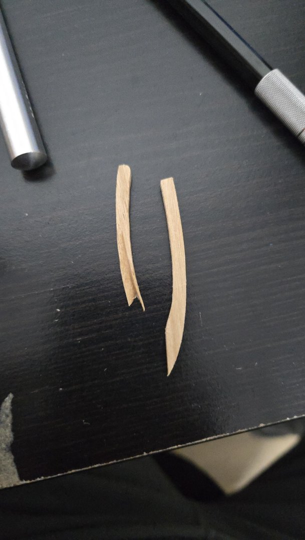
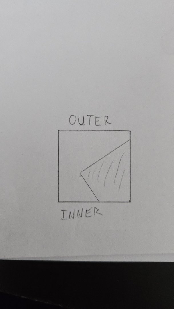
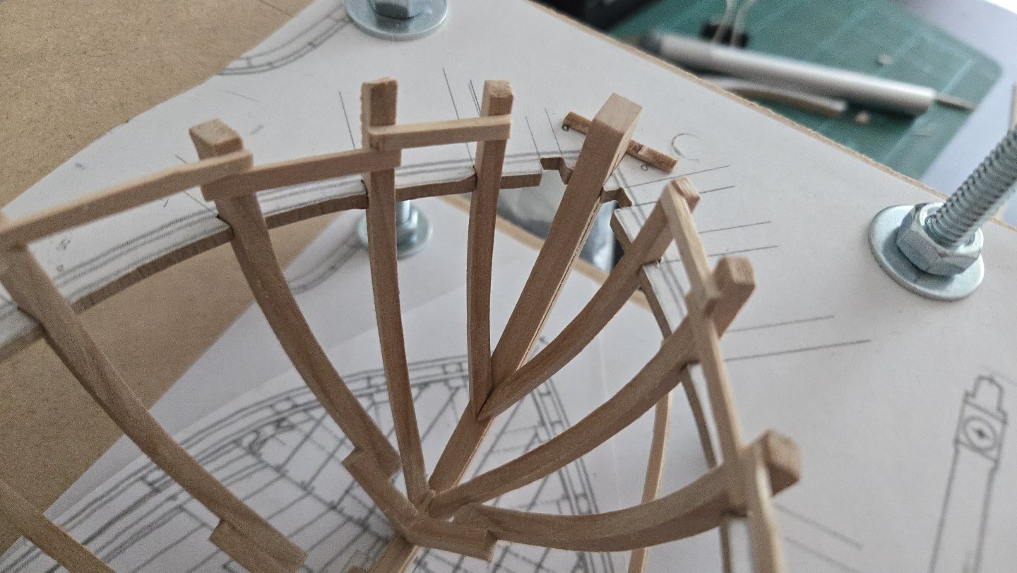
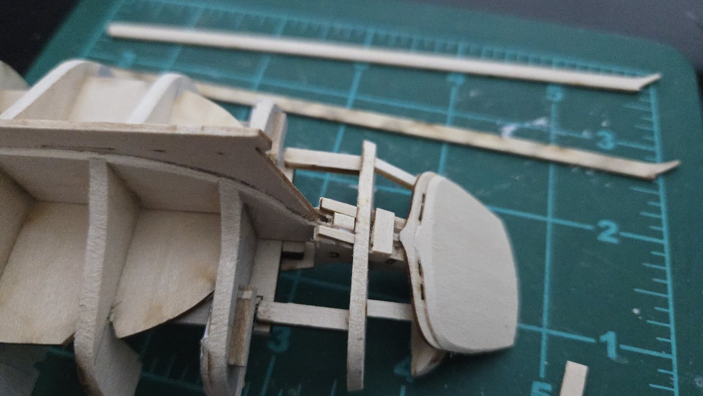
Thanks, @wefalck. I'll have to check out the watchmaking/repair shop here again. They seemed to have some interesting stuff. Unfortunately like many small shops here, their setup was not very amenable to browsing--I got the impression that you have to already know what to ask for when you go. I may have to redo some parts. Cant frames A turned out more challenging than I thought (I'll spare everyone my now-habitual complaining about the plans). Due to their position right alongside the keel, it was hard to test fit them until they were already shaped. Shaping them took a while, as they needed very long notches, curved to match the stem curve. I then glued them in position. Unfortunately, there ended up being quite a gap where they meet the stem. The starboard side is especially bad, the port side better but still not great. The aftmost part of the joint with the stem is also off, with the tips floating a bit above it. Apparently I added too much of a curve to the notch (after initially being unable to properly fit it because there wasn't enough of a curve). I'm debating whether or not to remake these frames, or at least the starboard one. Part of the problem is that I'm having a really hard time conceptualizing what the notch should even look like. I think that, at a certain point, it should be something like the drawing below showing a cross section of the frame piece, but the exact position would need to change along the length of the piece to match the angle of the frame-stem joint and the curve of the stem. I'm also not sure if the angle of the notch relative to the frame piece is really close to correct. So, on one hand, it would be better to have better-fitting frames here. On the other hand, I'm not at all confident in my ability to do a better job, given that I can't really figure out what shape the notch should be, and the jig makes it difficult to trial fit until you're already fairly close (but you also need the jig to trial fit in the first place). It's also worth noting that the second frame piece I made, not the first, is the one that turned out worse. I'm also not sure when I'll get the chance to go to the carpentry workshop again and would be able to cut new pieces--things are so busy with work that I really haven't been able to go, and have only been able to spend an hour here or there on modeling at home. Anyways, if anyone has any suggestions about the frame, I'd be happy to hear them!


- 139 replies
-
- 11
-
-
- ancre
- Bateau de Lanveoc
- (and 2 more)
-
Fantastic job, very precise work!
-
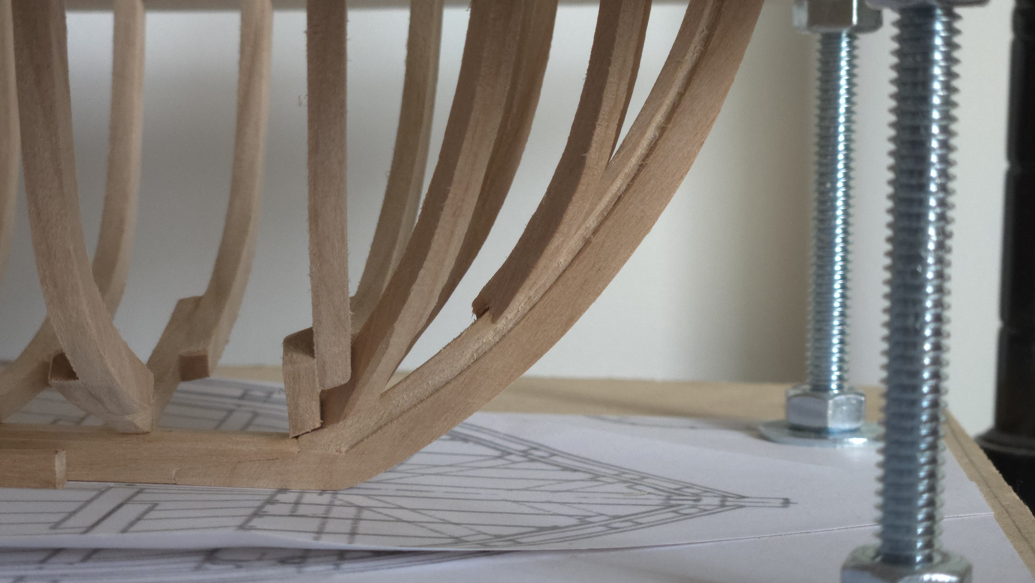
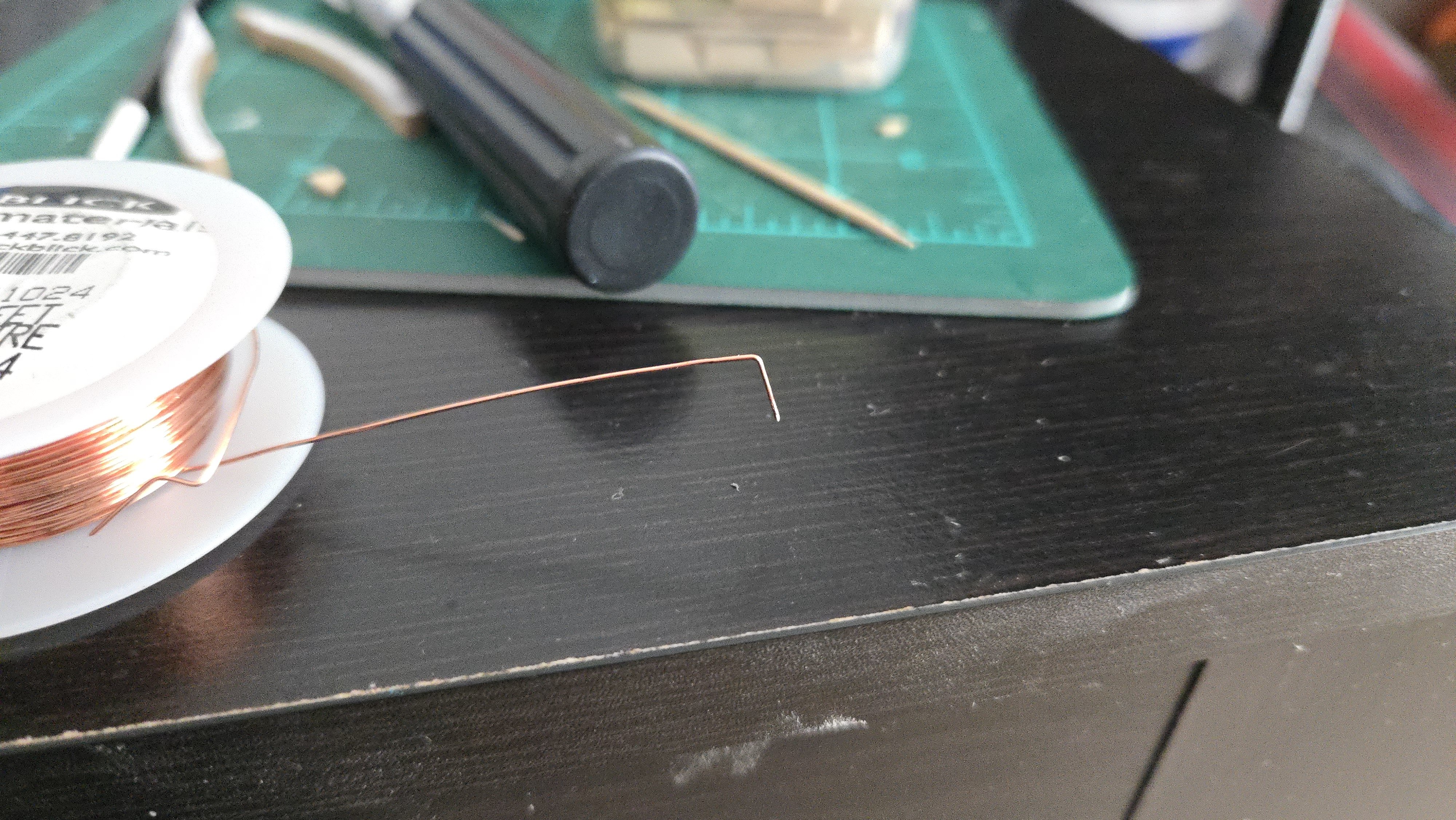
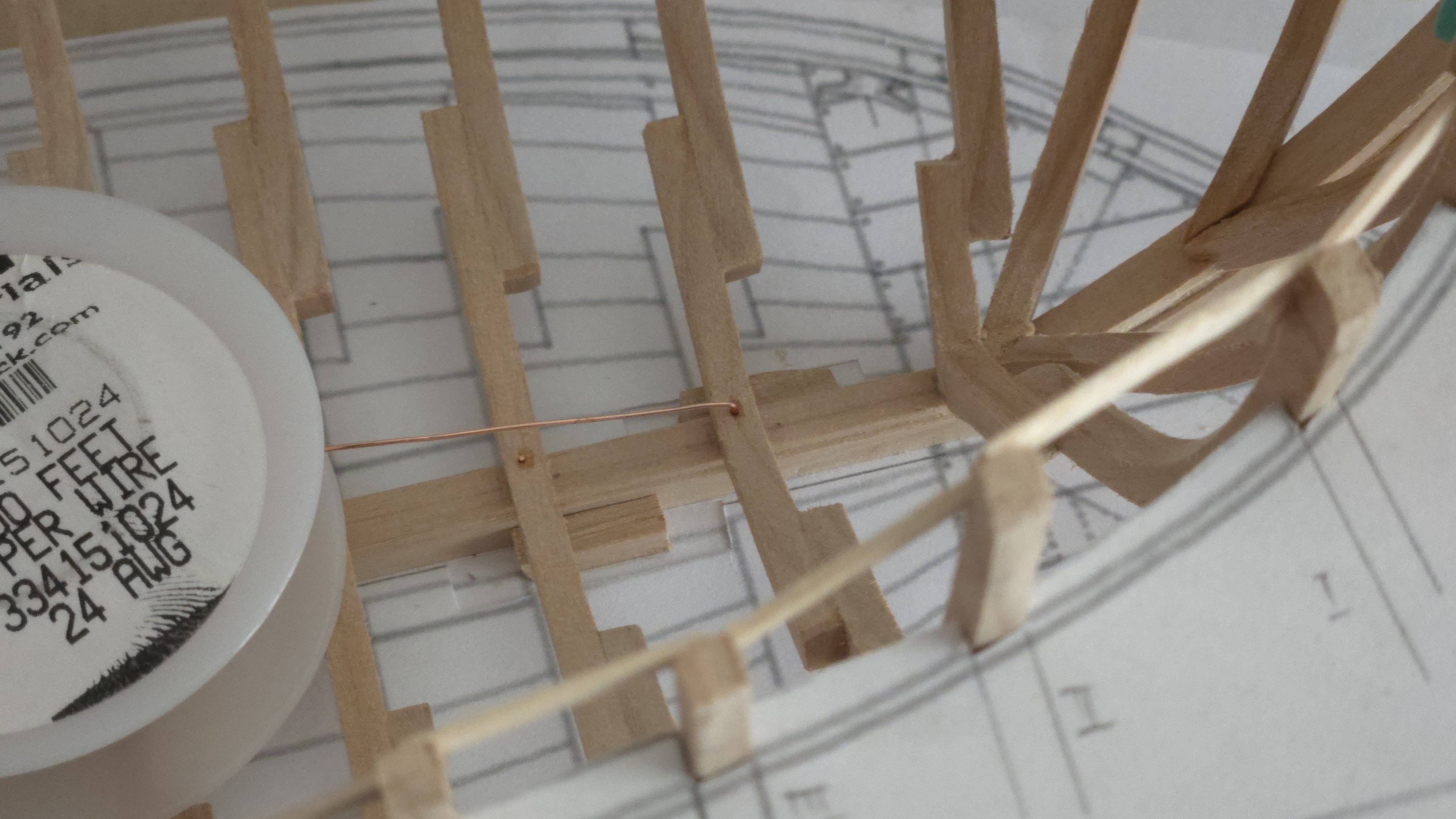
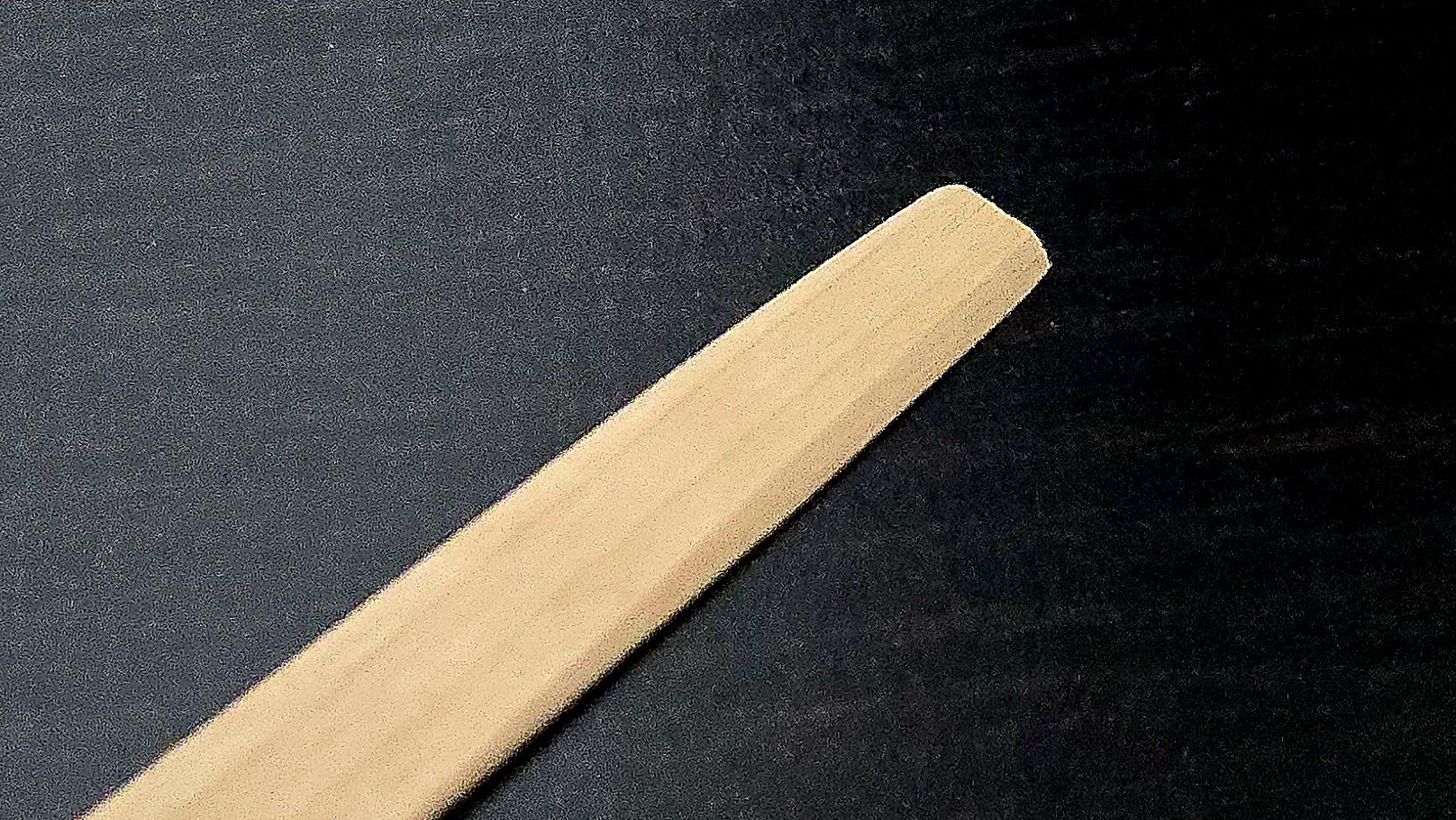
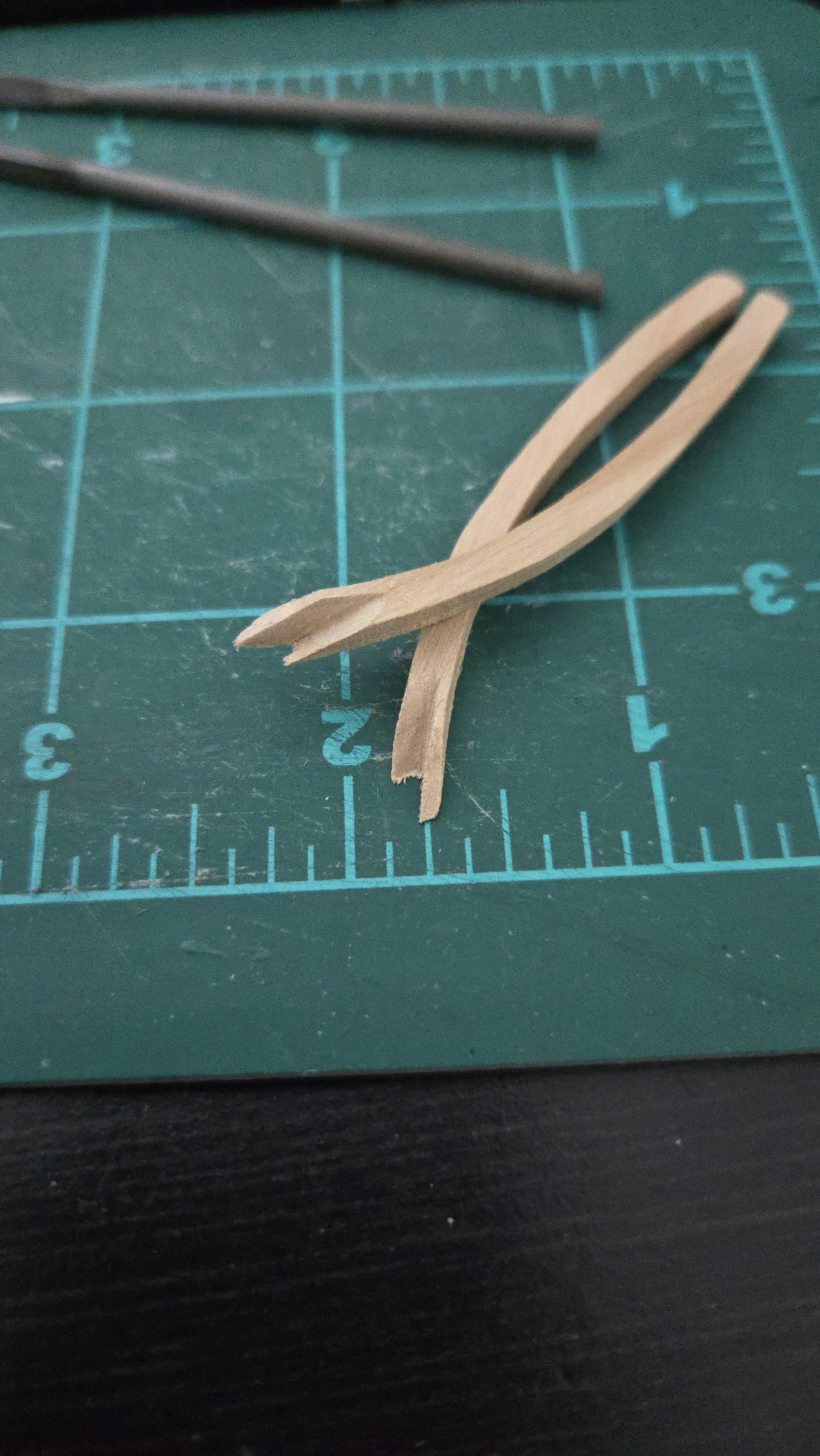
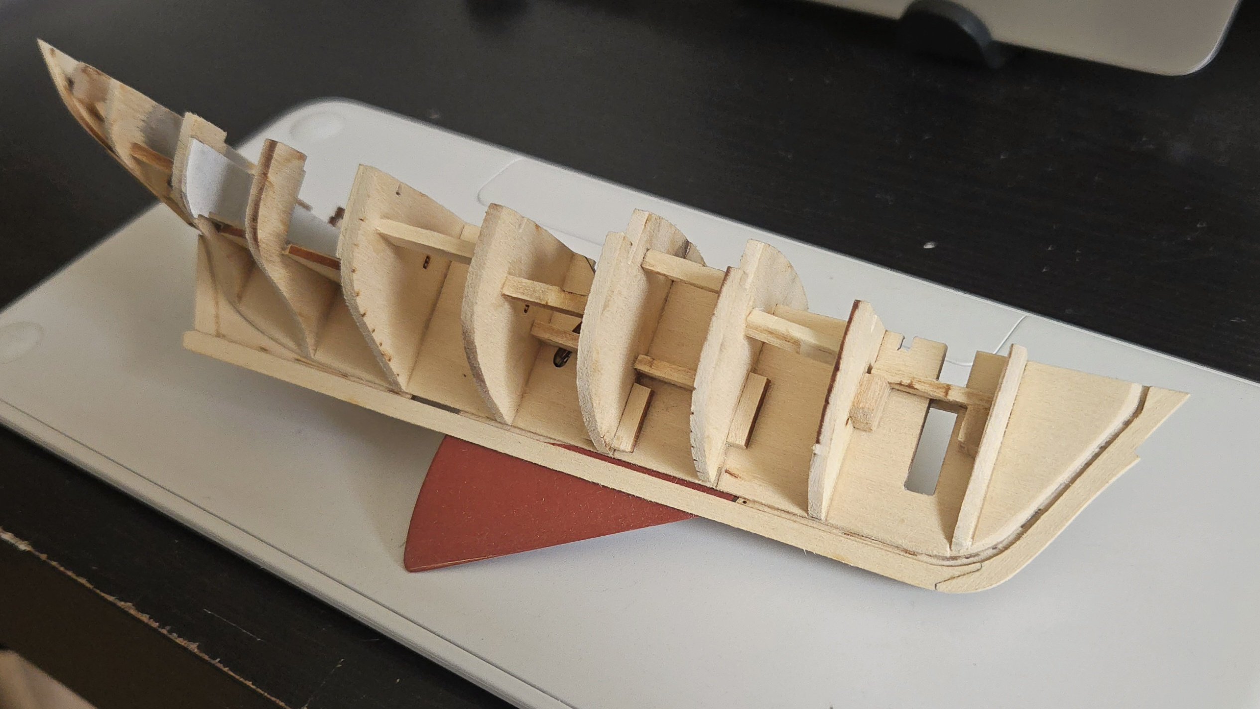
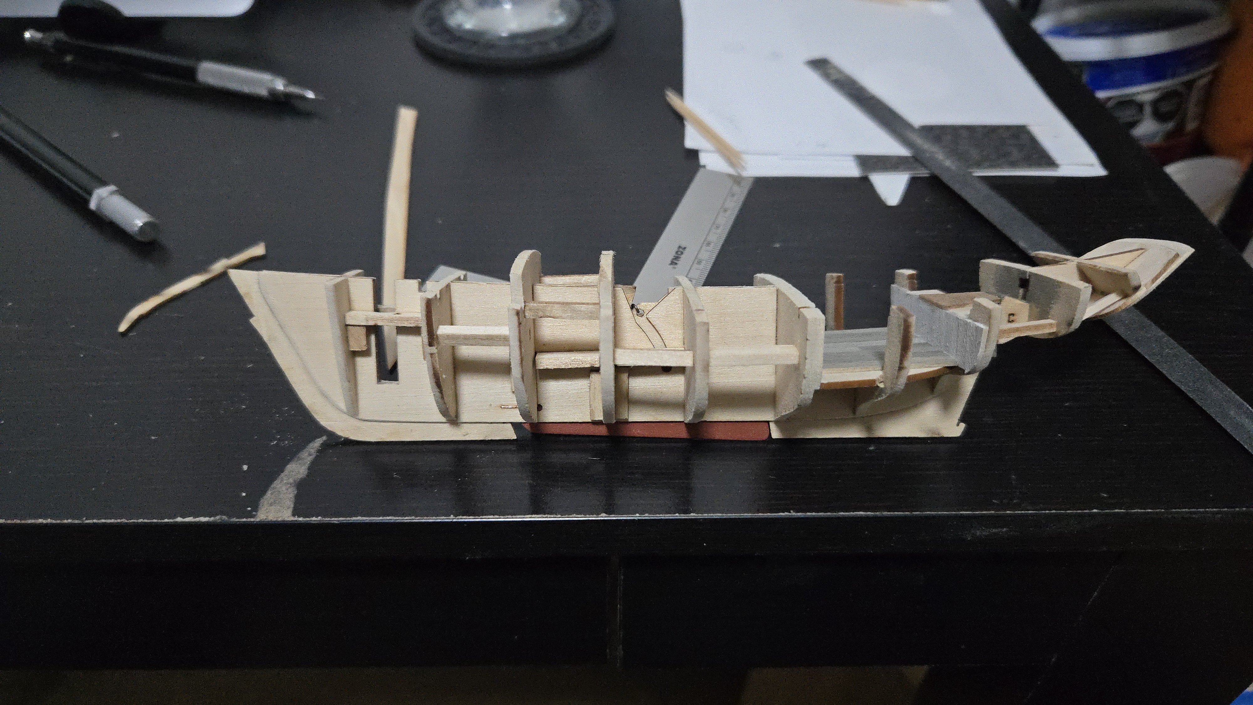
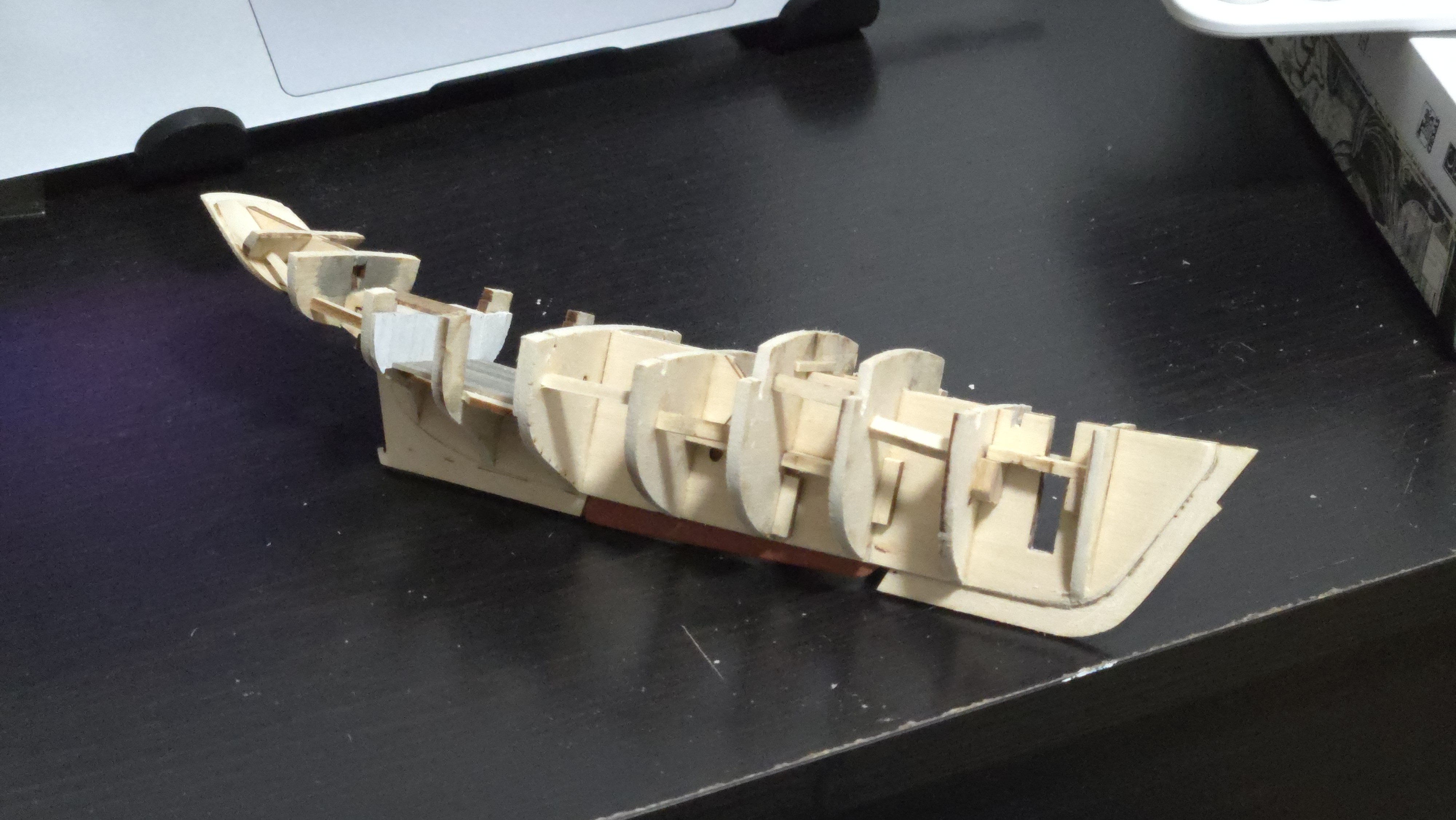
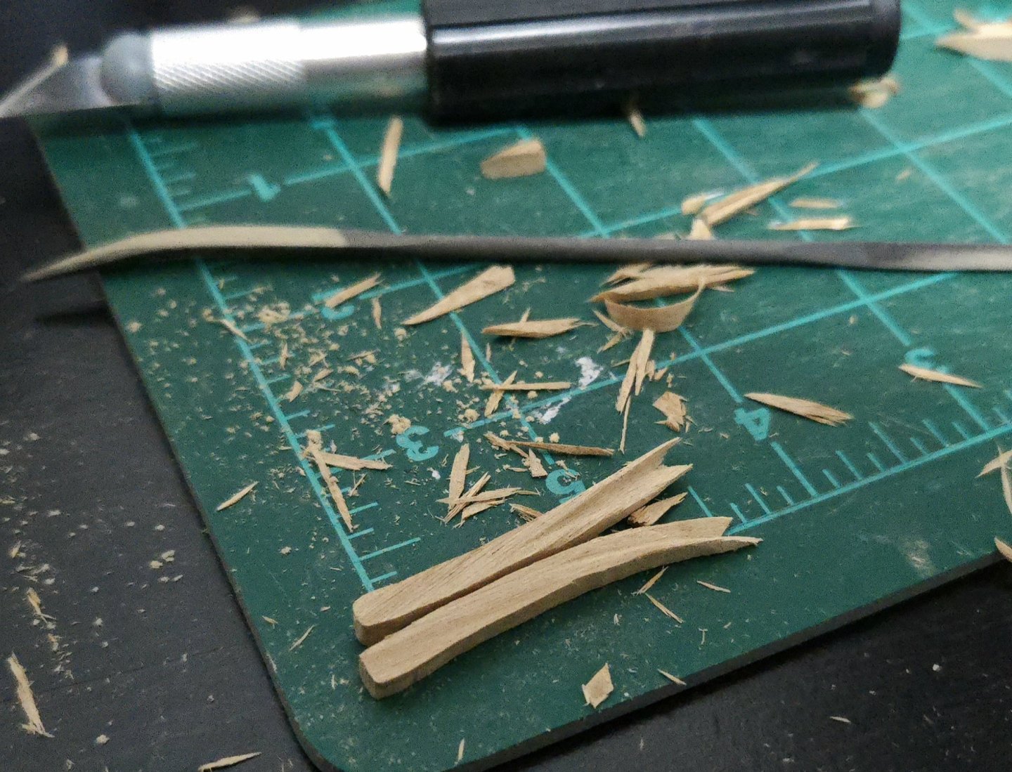
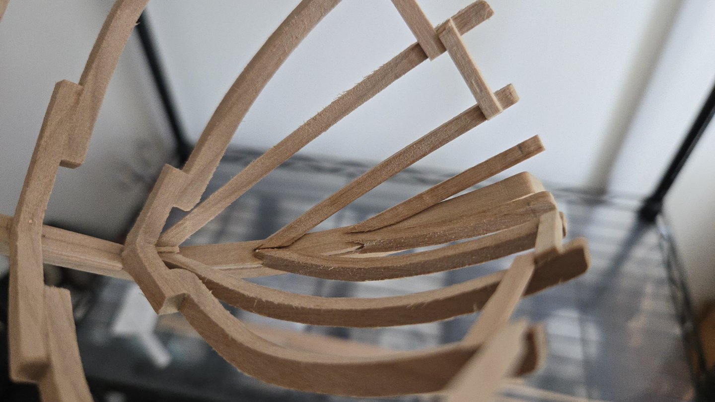
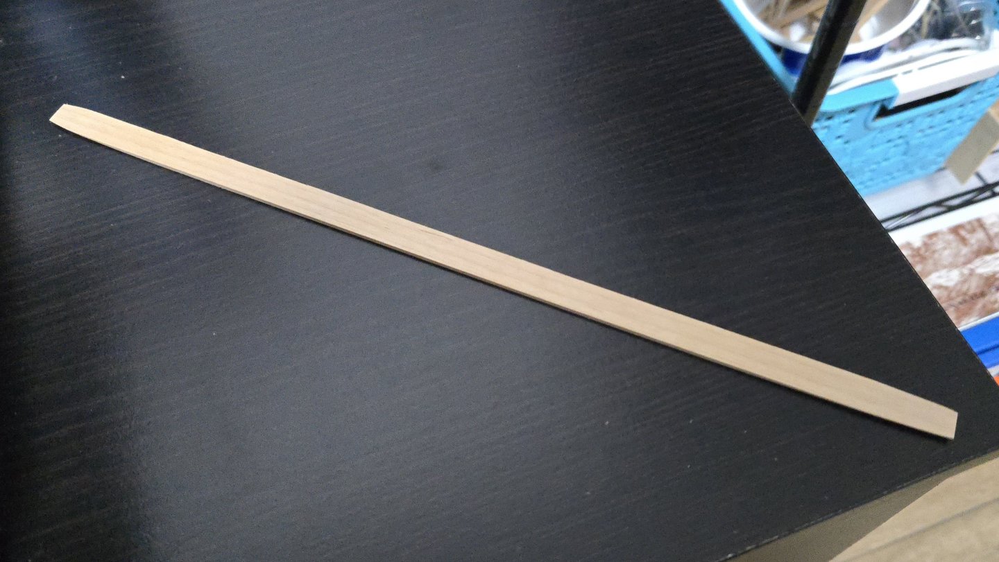
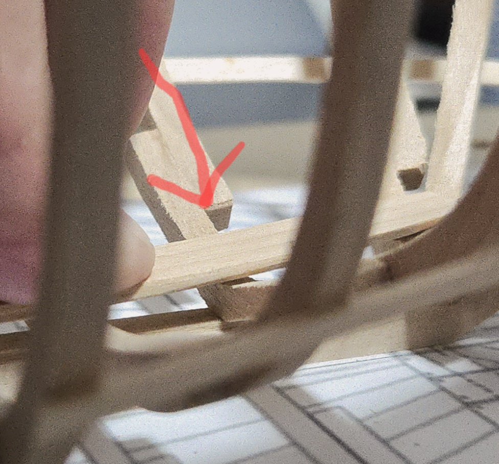
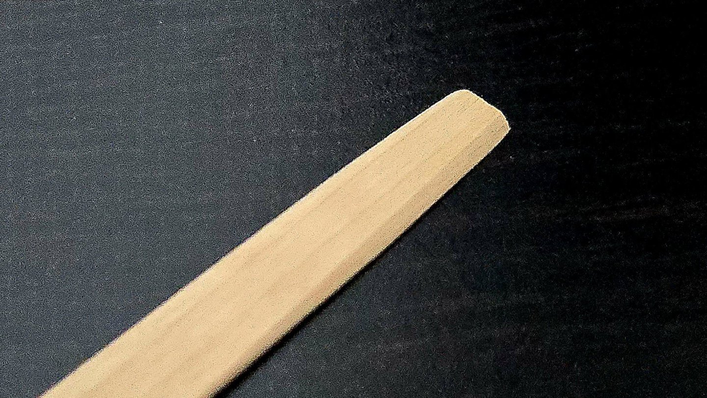
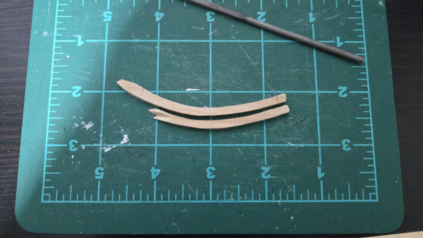
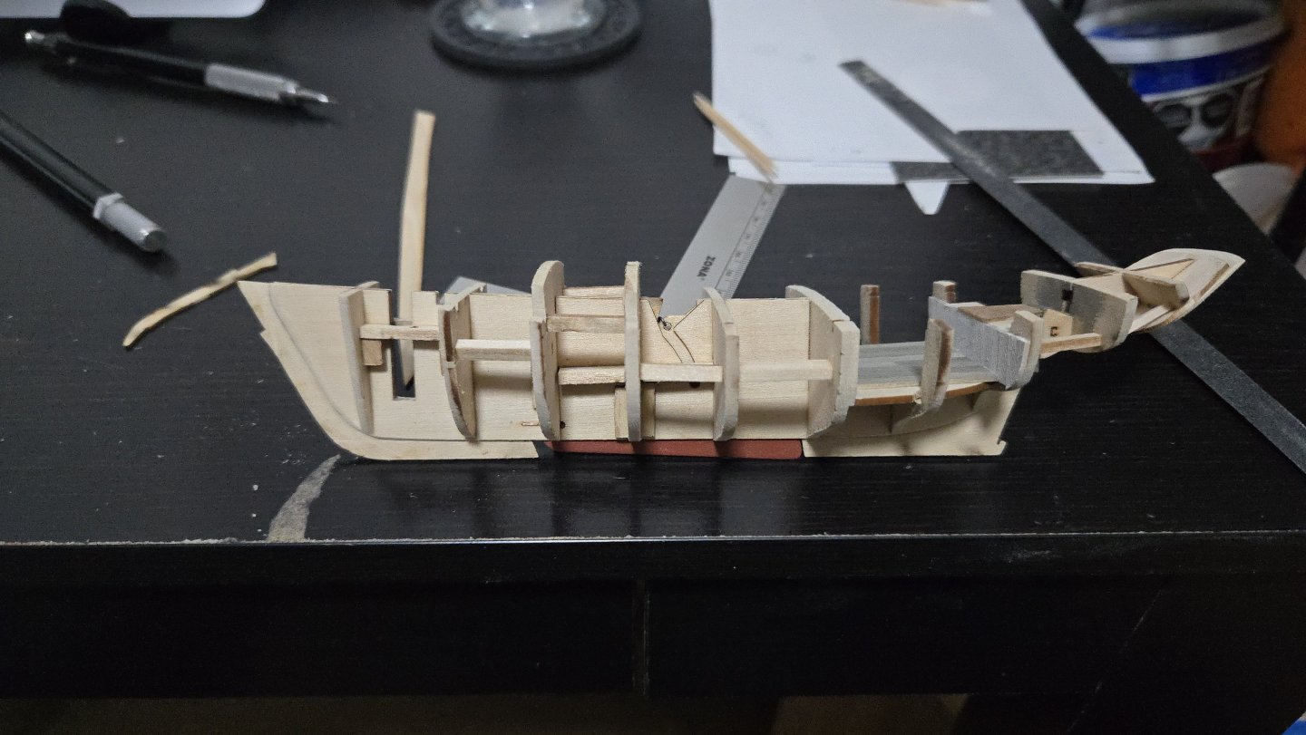
Thanks, Paul! I've found the time to make a bit more progress on this build. First, the keelson. This is just a long strip of wood, slightly tapered at both extremes. I'm making mine slightly longer than given on the plans to better cover the messy joints of cant frames C. Each end was also angled on the underside to better fit against the frames there. After a good bit of fairing, it fits smoothly across the frames, except for at frame 2 near the bow. I'm not sure if I cut the floor too thin here or what, but the keelson can't really be bent to fit onto this frame. I'm going to continue fairing frame 1, which I think is still too thick--the keelson is supposed to sweep up a bit at the ends, but maybe not quite this much--but I may have to add a support piece here. Second, cant frames B. As I've mentioned many, many times, the plans don't show the bottom ends of these. I had to trial-and-error my way into fitting them against the stem. One challenge is that the frames need to be on the aft side of the rabbet, but the frames are thicker than the relatively narrow ledge of the stem behind the rabbet. Checking photo logs of this model, I found that other builders have shaped these frames to fit onto the back of the stem--e.g., ending the frame in a notched joint rather than just a straight cut. I did one side first, constantly checking for fit and adjusting. It was a tricky cut to get right! By the time I had it right, the frame was a lot shorter than shown on the plans, as can be seen below (the parts were cut overlength, but the ends given by the plans are marked in pencil). Eventually I got both cut to shape. And I glued them in place. The joint with the stem didn't turn out quite perfect, but it should be stable enough and will be covered by the foredeck. Finally, I decided to pin the frames to the keel with a bit of copper wire and super glue, in order to strengthen the small butt joint there. It was tricky to push the wire all the way down into the holes because it easily bent and it was hard to get a grip to push it down, although it got easier once I started bending the wire at 90 degrees just above the length of the pin so that I could push down on the bend instead. Once all the pins were in, I was able to file them flush. I finally got to use the riffler file set I bought a while ago for this. Here's the current state of the build: Next, I need to add the last frames, cant frames A (which are basically hawse timbers or knightheads on either side of the stem). Given the highly acute angle where they meet the stem, these will be another challenge to shape.


- 139 replies
-
- 13
-
-
-
- ancre
- Bateau de Lanveoc
- (and 2 more)
-
If I remember correctly, I added some scrap wood to the edges to keep the frame sections lined up and tightly held in position.
- 45 replies
-
- 2
-
-
- Dory
- Lowell Grand Banks Dory
- (and 3 more)
-
I have no idea about this kit in particular, but it's pretty common for wooden boat kits to require a good bit of shaping to get everything lined up. One of the advantages of wood is that it's pretty easy to shape and, if there's a mistake, to glue back together. The model's coming along great!
-
Best of luck! Using a flexible sanding stick can be helpful for sanding several bulkheads simultaneously, which can really help keep them fair.
-
To be honest, I think you're going to have a hard time getting a satisfactory second planking with the first layer like this. There are a lot of large gaps and general unevenness. Getting a decent second layer requires a smooth first layer. There would be a lot of very tedious filling and sanding required at the moment to get to that point, and it would be quite challenging. The area over the square cutout at bulkhead 3, for instance, will be very hard to plank over without having an incongruous flat spot there. From the photos, it looks like the bulkheads weren't faired enough, which explains the gaps and probably the space between false deck and planking at the bow. You should be able to run a batten (a thin strip of flexible wood) over the bulkheads, at every point in the hull, such that it touches all of them evenly without bulges or spaces. Especially near the bow and stern, this usually means substantially beveling the bulkheads and taking off a surprising amount of material--usually there should only be a thin line of laser char left. There's an example of this in post #21 in my NRG Half-Hull build (and you can see the long slow process of fairing in the posts before that one): All of which is to say, I think you'll have a much easier time down the line if you remove this planking, fair the bulkheads more, and redo it. Following Mastini's advice to taper the planks is also a good one. Planking a hull is one of the hardest parts of ship modeling, so I wouldn't feel discouraged, but I think it's worth it to try to get it right to avoid frustrations down the line.
-
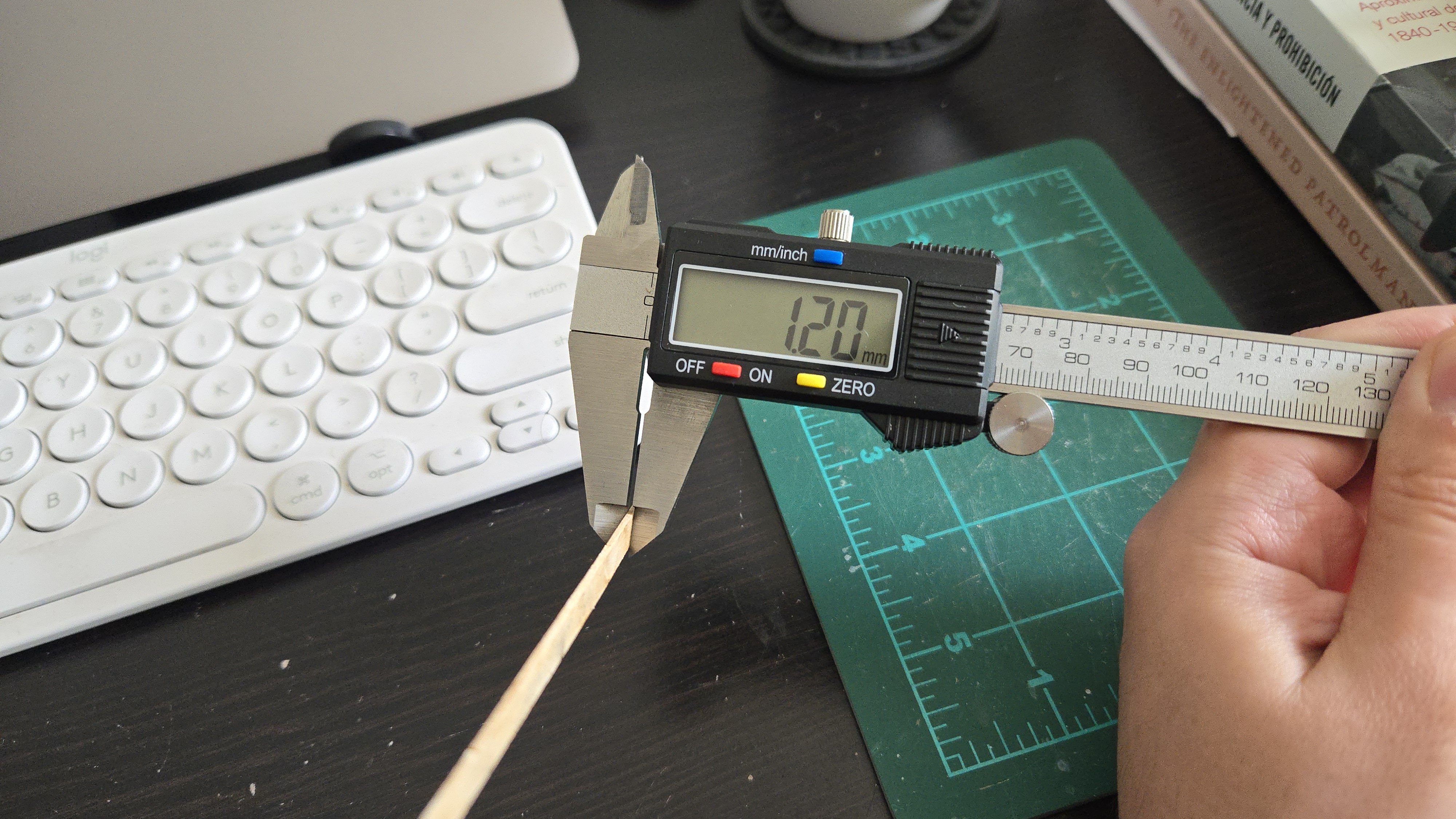
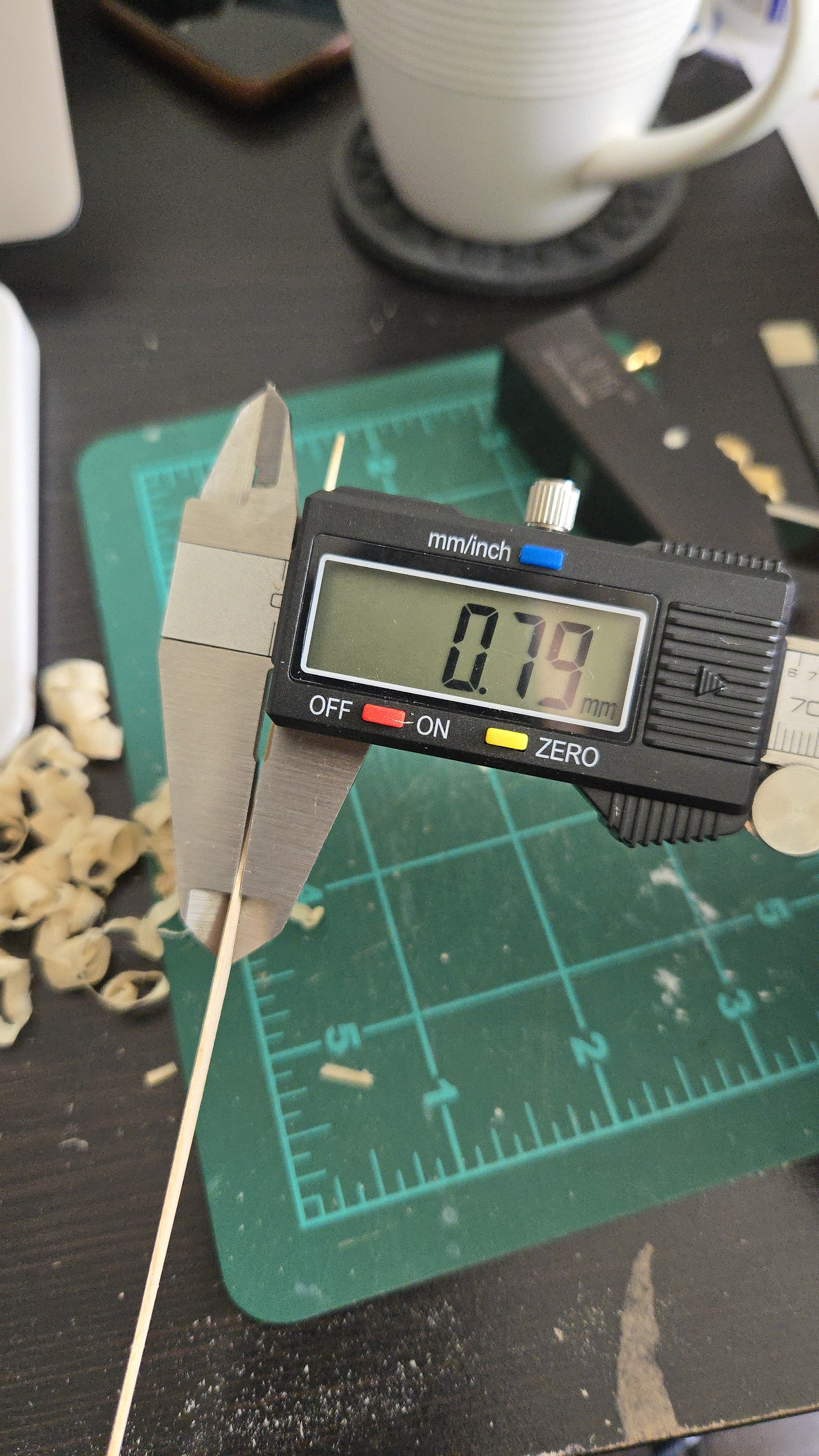
Thanks, @wefalck! The chamfering shouldn't be too bad, I think. Working out the run of the planking around the overhanging stern is a little tricky, though, and I'll have to take some time on it. I was curious to know whether the kit designed precut planks could be at all modified to serve as the basis for at least some of the lapstrake planks. This could in theory help a little with the complexity of the stern, and would also enable me to use the wood that's already been laser-cut. Looking around at images, it seems like most vessels had around 15-18 strakes of planking. (See below, for instance--granted, this is a deeper Friendship Sloop.) Source The kit design has 11 including an extra-wide sheer plank (which could be split in half or so to be about doubled). Both photos and kit are, of course, caravel planked. I'm assuming that a lapstrake planked vessel would probably use a similar number of planks, or perhaps very slightly fewer (as I'd imagine that it would be easier to use slightly wider planks rather than narrower ones, given the need to overlap planks. Taking a few preliminary measurements, it looks like the largest bulkhead measures around 2 inches. The precut planks are generally around 3/16-inch wide. So, if they were overlapped by, say, about 3/64‐inch, that would lead to around 15 strakes per side. Of course I need to do a lot more planning work, but I think I may be able to use the precut planks as the basis for at least some of the planks. I'll have to line off the hull and check how things look first, though. I thought I would try to dry-fit a precut garboard strake just to see what it would look like. I found it extremely difficult to bend into shape, even when soaked and heated. There's a pretty drastic twist from the stern to amidships, then another at the bow, over a fairly short distance of a little under 6 inches. I then checked with my digital calipers and found that the 1/32-inch thick basswood I had bought was actually 3/64 inches thick! (Dimensions shown in millimeters. 3/64 in = 1.19mm; 1/32 in = 0.79mm). I began planing it down to size with my mini-plane. This went pretty quickly, although I had to check repeatedly to make sure I wasn't angling the wood and creating an uneven thickness. Below: getting closer. And finally there! After being thinned, the plank bent easily into place even without being soaked or heated. Looking at it, my sense was that it looked a little too wide, especially aft. However, I soon realized that it would actually look narrower due to the overlap of the plank above. If I set the overlap for around 3/64 inch, it should look pretty good. It's also worth noting that, based on the photo below showing the stern of a Maine lapstrake sailing vessel, the Whistler, with a similar overhanging stern (although it's rather smaller than the vessel I'm modeling), it looks like having a wide garboard plank aft was entirely possible. In this case it's combined with a triangular deadwood piece, which is interesting to see although I don't think I'll be adding that. Source Anyway, I clearly have a lot more work to do on this, especially with lining out the hull and planning the chamfers, but even just fiddling around with the precut planks is helping me get a sense of how the strakes should run, especially at the stern.


-
Best of luck with the back! Your dory diorama project sounds like a great idea. There are plenty of paintings by Winslow Homer and Andrew Wyeth of dories drawn up on shore or in harbor that might serve as inspiration.
- 44 replies
-
- 1
-
-
- maine peapod
- peapod
- (and 4 more)
-
After a bit more work with the sanding sticks, both sides are now faired. This hull has been much, much easier to fair than my Lancha Chilota build was. The only real issue has been that I think I didn't quite get bulkhead 2 seated properly so it ended up being less sanded than the other bulkheads. I also realized that I needed to build up the area around and just aft of the opening for the rudder, as it was a bit low. I added some scrap and sanded it fair later. Next up, attaching the outer pieces of the keel, stem, and sternpost. The joint of the stem turned out nice and tight. It's good to see that my rescaling and conversion for laser cutting didn't ruin these parts! Next up, I'll be starting planking. This will be my main modification from the kit design*, as I'll be doing lapstrake instead of carvel planking. This will definitely be a challenge, and I'm looking at other build logs for inspiration. Druxey's Greenwich Hospital Barge log has some great information for lapstrake planking in a relatively small build. *I had almost tried to reshape the bow to do away with the beakhead and to be more vertical, but I realized that, besides causing difficulties in fairing the hull, it would also substantially reduce the area to affix the bowsprit. Modeling something like the Muscongus Bay sloop photos I've shared with plumb bows would probably be easier as a complete scratch build rather than a rescaled kit.


-
Very nice work, the hull lines really shine through! That Brazilian pine seems to work really well for planking, it looks a lot nicer than the pine I've been using for non-modeling purposes.
-
It's definitely an interesting hull shape. I have to wonder what purpose the sharply raked stern served.
- 49 replies
-
- 1
-
-
- Lady Isabella
- zulu
- (and 1 more)
-
While my modeling time has mostly been focused on the Bateau build, I've progressed a bit. The next step is fairing the hull. The kit design would have you add the deck now to stiffen the hull for fairing, but I won't be adding the deck until much later so I can more easily build the cockpit. So, as the frames felt a bit fragile, I added supports between the bulkheads. I've also started fairing. My method for a small hull like this is to first use a batten to check which frames seem especially high at the top, middle abd bottom of the hull, taking notes on this. I then fair with a flexible sanding stick, and a curved sanding block in the hollow of the lower aft hull, giving special attention to the high frames. It's then a slow process of continuing sanding and checking fairness with a batten. By this point, I've gotten the starboard side and the deck mostly fair. Next up will be the port side, then I'll check both sides for evenness and final fairing.


-
Getting back on the horse....
JacquesCousteau replied to Sterling59's topic in New member Introductions
Welcome! The NRG Half-Hull is a great kit for learning planking, although definitely a bit challenging. I'd highly recommend checking out build logs, if you haven't. -
That's what I get for not zooming in more.... Still an excellent mug!
- 489 replies
-
- 2
-
-
- minesweeper
- Cape
- (and 1 more)