JacquesCousteau
-
Posts
1,362 -
Joined
-
Last visited
Content Type
Profiles
Forums
Gallery
Events
Everything posted by JacquesCousteau
-
 Nice work!
 -
That's unfortunate. It's odd to me that they haven't updated to at least basic wooden ones, as model expo makes and sells those and includes them in model shipways kits. Why not simplify production? At least better replacements aren't too hard to find.
-
Looks like a fun little build! I'm curious, are the blocks wood or plastic? I know I've seen some mentions of plastic blocks on the older kits, I don't know if Model Expo updated that when they restarted production.
-
Thanks, all! @Some Idea, I hadn’t remembered that from your build. Looking at it, your repair really is pretty much invisible. It's good to know that the shellac shouldn't give me any trouble on this section.
- 139 replies
-
- 3
-

-
- ancre
- Bateau de Lanveoc
- (and 2 more)
-
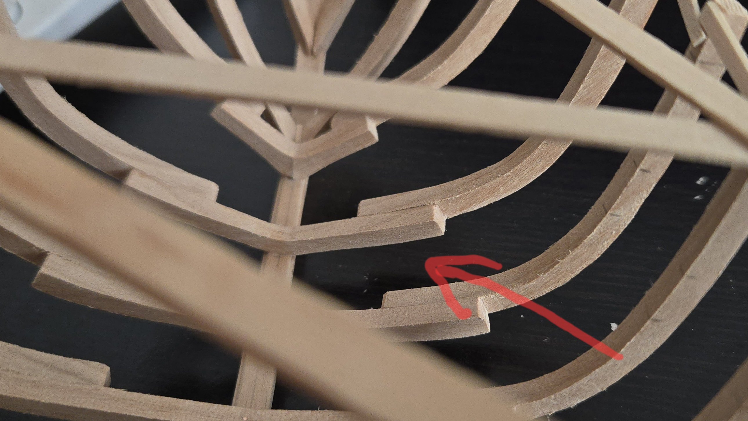
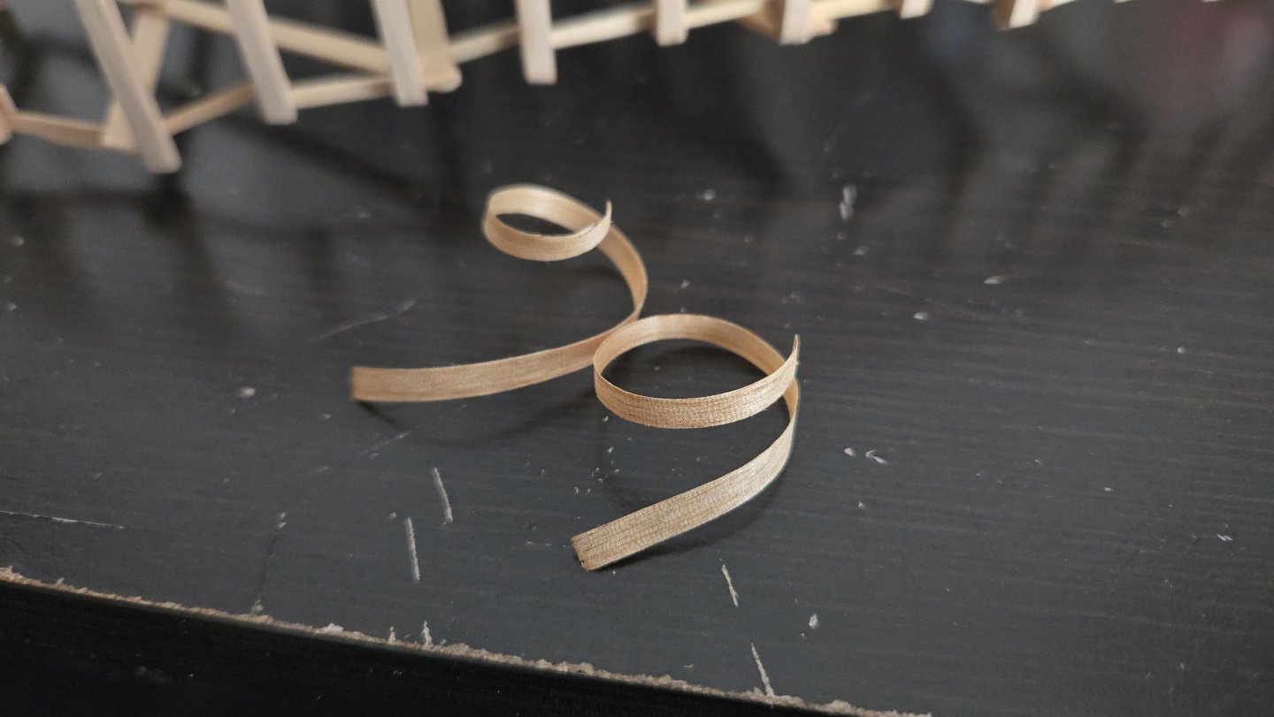
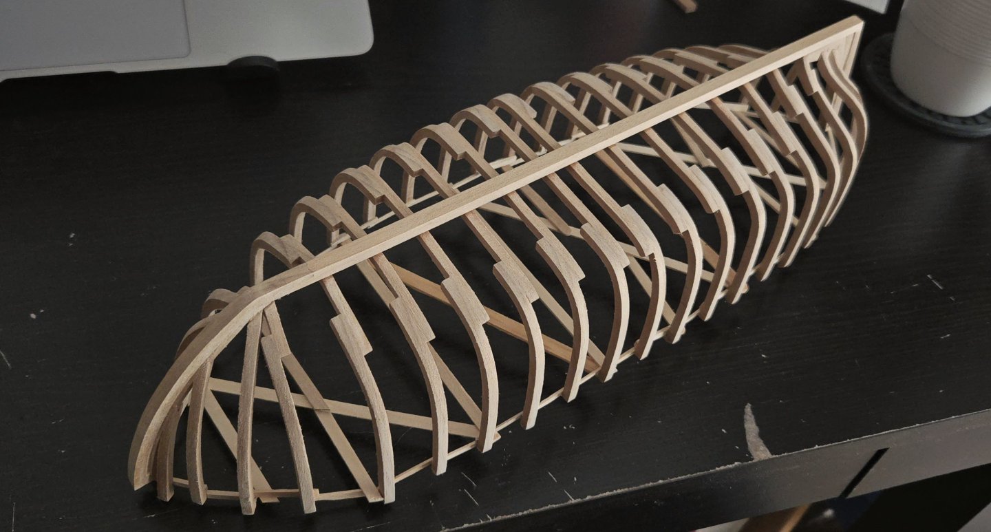
Thanks, all, for the comments and suggestions! I decided to try layering some thin alder shavings. After trimming and sanding, the repair is not very noticeable. The built-up frame is indicated below, it looks pretty much like the other frames. Some layering is visible right next to the keel, but that will be covered by the garboard. From ahead, a very thin line from the layering is visible, but only barely. And from aft, the only way it will be seen if I totally plank the hull, it's negligible. I assume that the repair would be more visible if I applied an oil finish, due to the glue blocking absorption, but at the moment I'm thinking of finishing the hull interior in shellac. I'll have to test whether shellac over glued wood looks all that different from shellac over unglued wood.


- 139 replies
-
- 8
-
-

-
- ancre
- Bateau de Lanveoc
- (and 2 more)
-
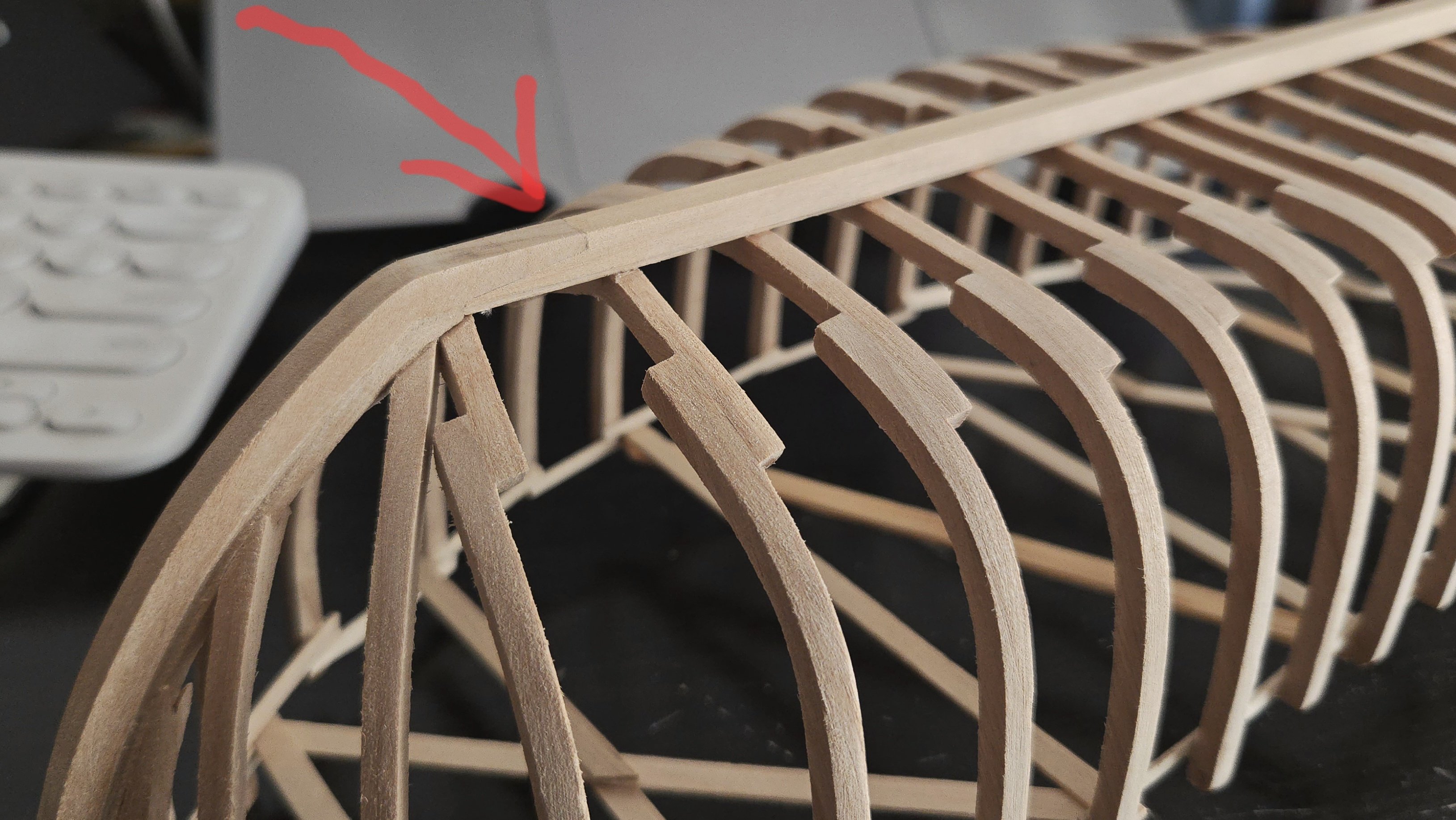
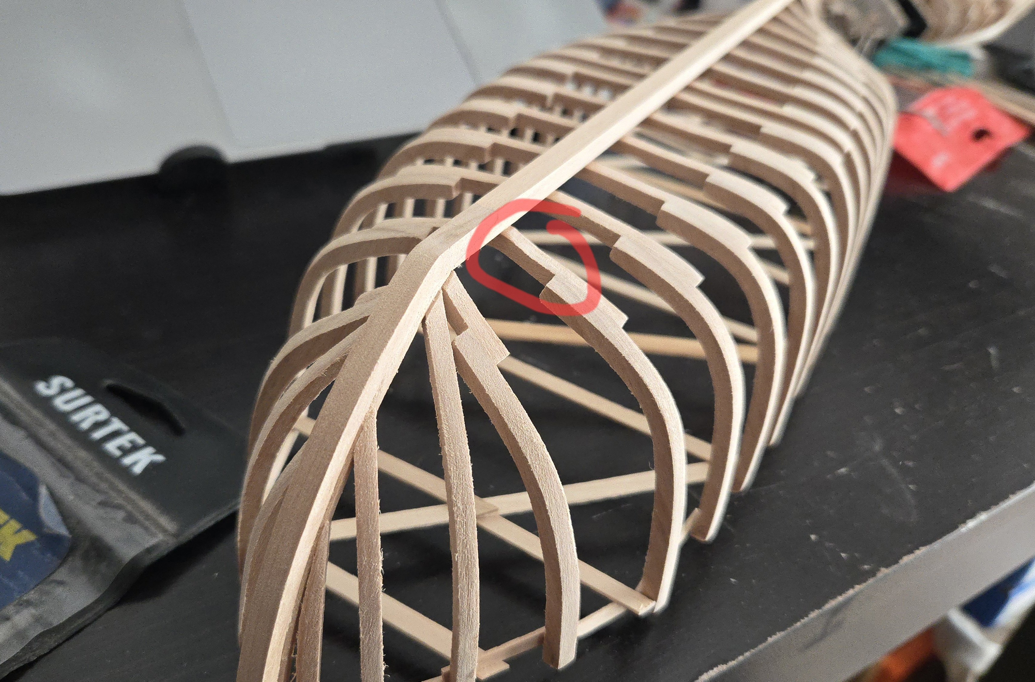
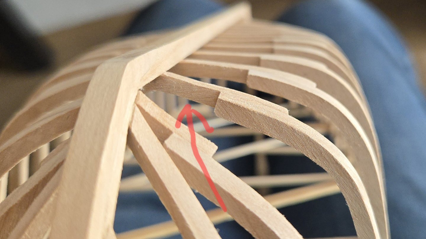
Fairing continues to be a slow, tedious process. Having already finished the port side (more or less), I'm now about midway through fairing the starboard side, starting at the bow and moving aft. In general, I wish that I had cut the frames slightly closer to the lines, as I left a lot of meat on them which has made for a lot of sanding. On the other hand, I've come across a frame that's too low in one spot. Frame 2's floor is a little too low compared with the other side, low enough that I can't simply sand down the other frames to meet it without throwing off the hull shape compared to the other side. I had noticed the divot when I was making the frames, but as it didn't go below the line, I thought I'd be able to fair it out. Ths spot is circled below. As I see it, I have two options here. One is to remake the floor. This would give the nicest end result, but would also take a lot of work--debonding the floor not just from the futtocks, but from the keel, where it's held by a pin as well as glue, and then getting everything glued up properly without screwing up the existing fairing. The second option would be to build the frame up slightly with some thin layers of planed alder, cut from the same thickness as the frame parts. I think two layers in the lowest part of the divot should be enough to bring it fair again. The repair will be covered from the exterior by the planking, although this will require me to plank up to at least that spot and not leave the lower hull open, something I was considering doing. The view from the interior will be blocked from above and ahead by the foredeck, but may be slightly visible viewing from aft. That said, I don't think it would be all that noticeable. Any suggestions? I'm leaning toward trying the second option--if it works, it is the much easier repair, and if it doesn't, that piece will need to be replaced anyway.

- 139 replies
-
- 7
-
-
- ancre
- Bateau de Lanveoc
- (and 2 more)
-
Thanks! It's definitely a bit different from carvel planking. I'm still having trouble getting the joints in each strake to line up well. I should also note that I've snapped off each side of frame 7 in the cockpit at least twice. It hindsight, I may have scored it for easy removal a little too early.
-
Thanks, all! The planks are indeed curved, all are made from templates tracing on masking tape. Between travel and some other projects, planking has been very slow, but today I reached a milestone. The sixth strake has been placed and I am now midway through the planking. My previous planking band ended right at the top of the sternpost, and I was a bit concerned about how I would transition to the overhanging stern. It actually wasn't that complicated, although as can be seen below, unfortunately one plank was a little low and I couldn't fully seat the plank end flush. I also accidentally spaced a plank a little far off the one below it at the bow. It's hard to see the planks once the clamps are in place, I'm guessing it slipped as I was adjusting the run aft. In both cases, and a couple other spots, I was able to add a tiny bit of filler. I've had some trouble with clamping due to the position of the supports I added to the framework. In the future, I'll have to remember to place them a bit further inboard. And that brings me up to the halfway point in planking. Six strakes down, six to go.


-
Despite the challenges, the model looks great so far!
-
Very good question, hopefully someone has a good answer! I think that looking at paintings of the subject, period, and place might be a good start. At the very least, it would probably give you an idea of typical paint schemes. Of course, that will only get you so far as artists undoubtedly changed the exact shade to capture different lighting conditions, express different moods, and fulfill other artistic purposes, but comparing several paintings may allow you to triangulate something like the original.
-
Nice progress! I think that when I used bobby pins and rubber bands on my build, I pushed the pins all the way down against the bulkhead/former, so that the pressure on the rubber band forced the plank to twist and hold flat to the former. It was tricky, though.
- 24 replies
-
- 1
-
-
- maine peapod
- midwest products
- (and 1 more)
-
Very nice work! Before going on to the masts and rigging, you may want to check that the blocks aren't backwards (the one at the tip of the bowsprit looks like it is). Real blocks are basically pulley wheels in a casing, but many modeling blocks just have a single hole to represent this. So you would want to set it up so that it looks like the rope is passing over the wheel, not below it, if that makes sense.
-
Nice start! For what it's worth, posting in some detail can actually be really helpful, not just for yourself, but for anyone else who builds this model. Maybe you'll come across different challenges than other logs described, or resolve them in different ways. Don't sell the quality of your work short!
-
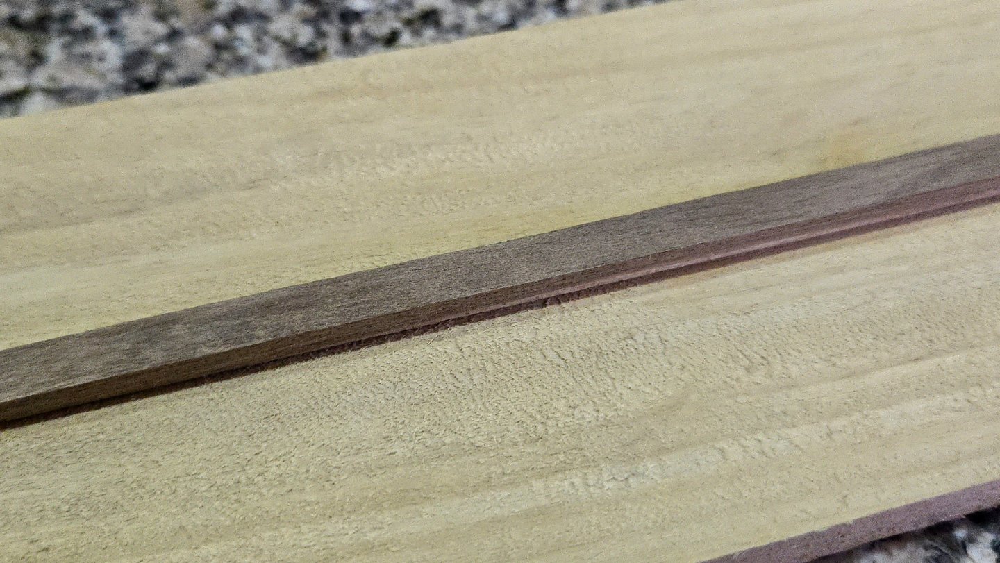
It's easier to see the color of the xochicuahuitl bars in the following photo: As can be seen, the color is pretty close to the cherry base. I'm now realizing that this build may end up going a little overboard in terms of using a different type of wood for nearly every subsection. Oh well, part of my goal with this build is to try out different woods and finishes than I have previously worked with.
- 32 replies
-
- 15
-
-
-
- NRG Capstan
- NRG
- (and 1 more)
-
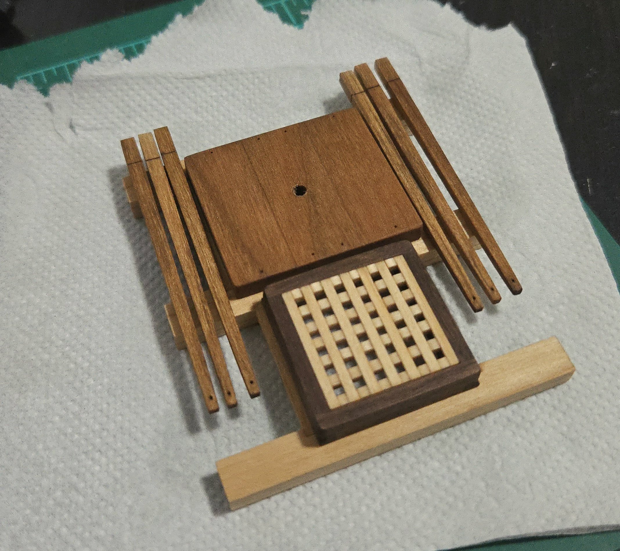
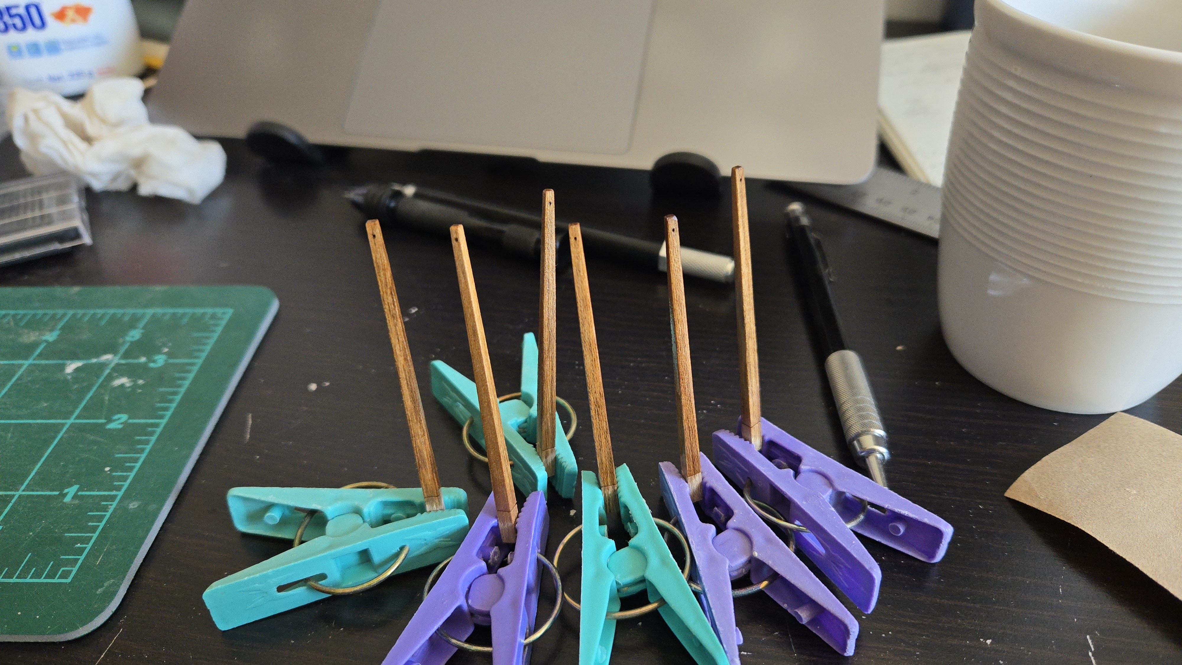
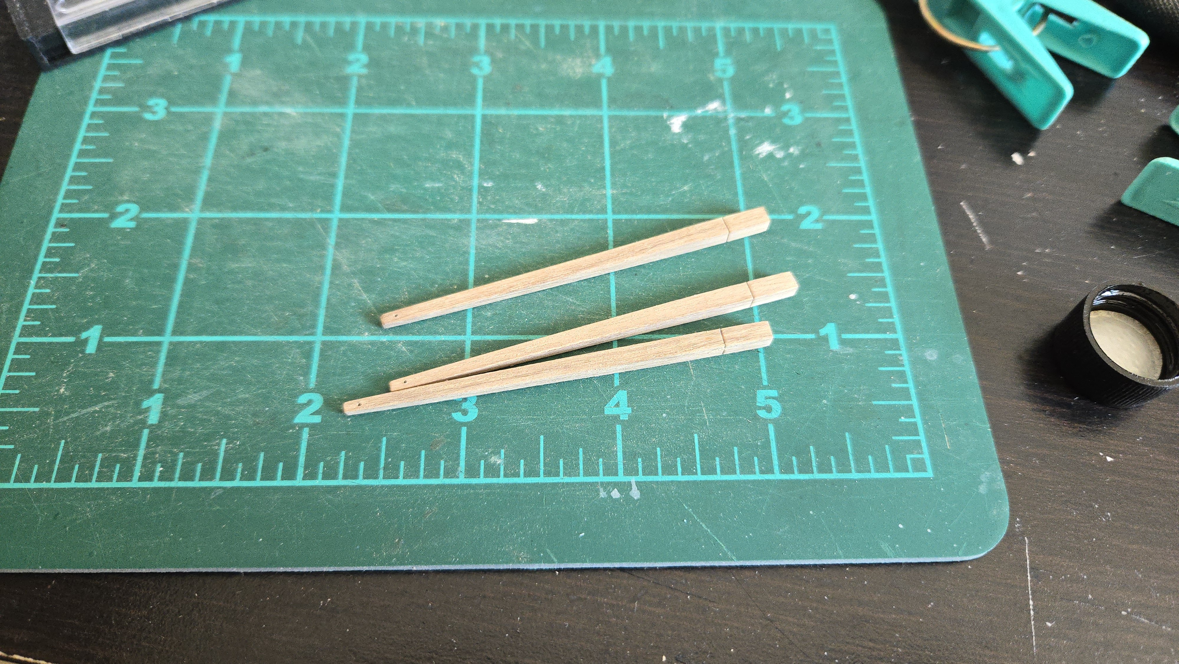
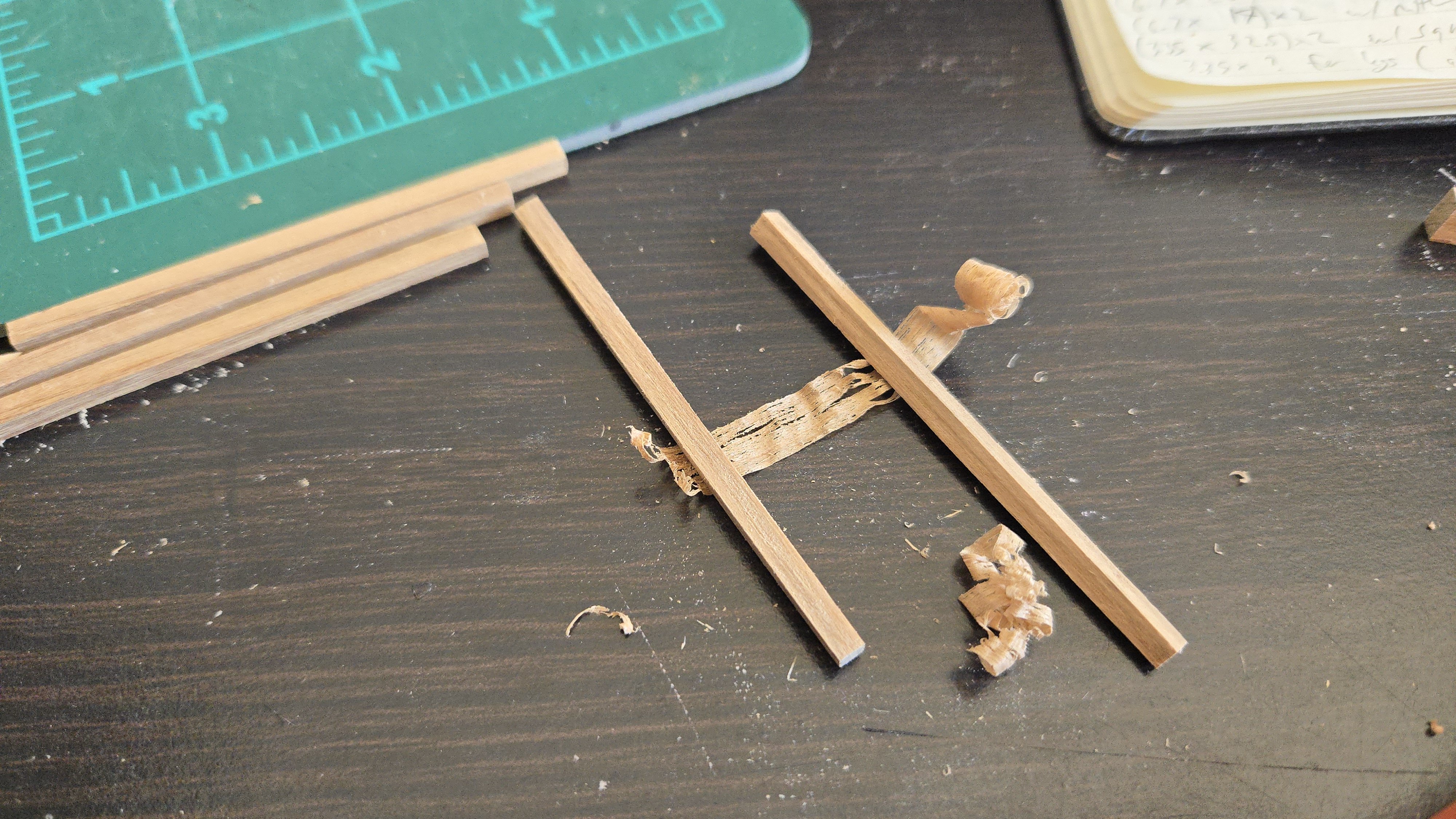
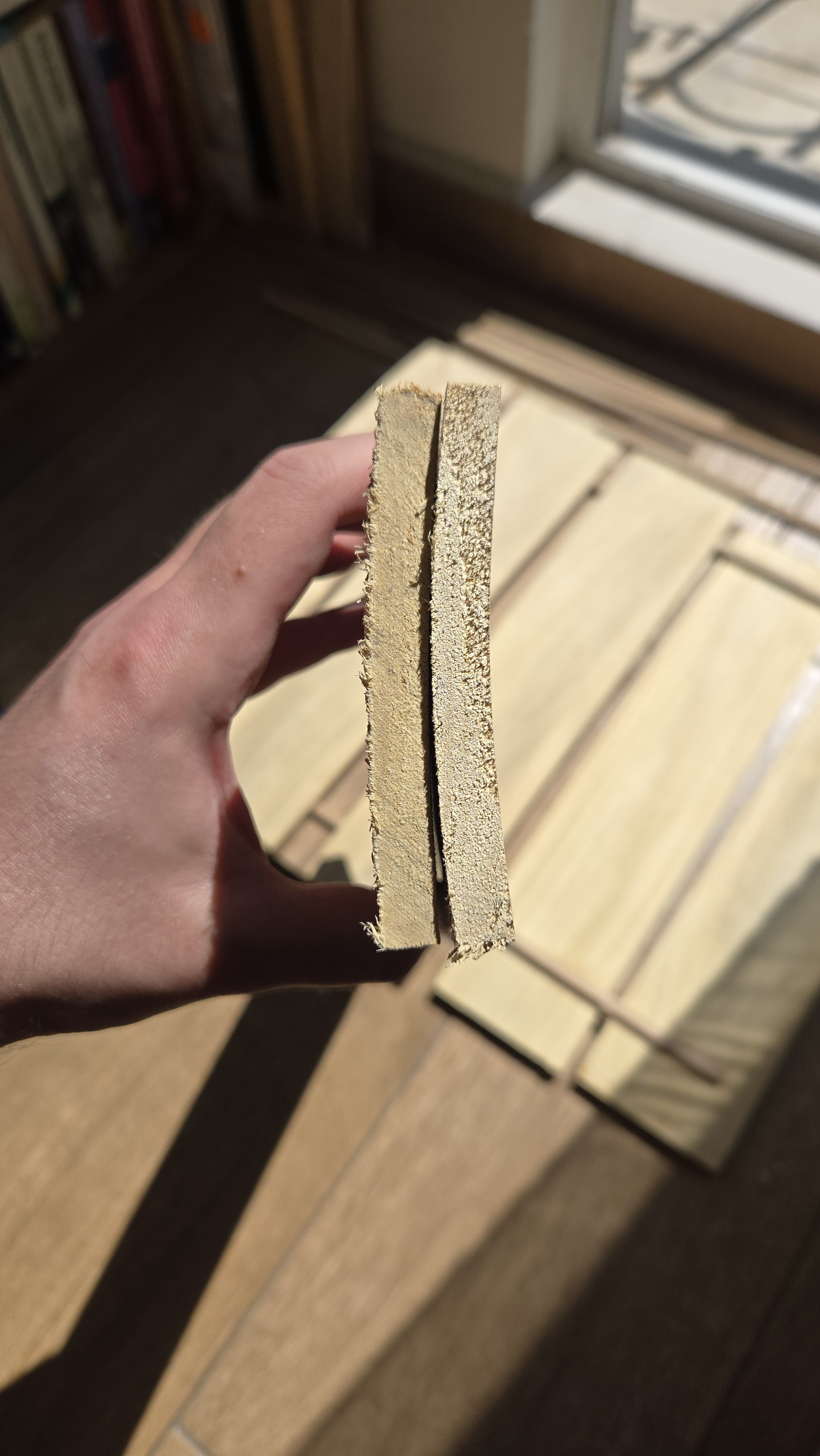
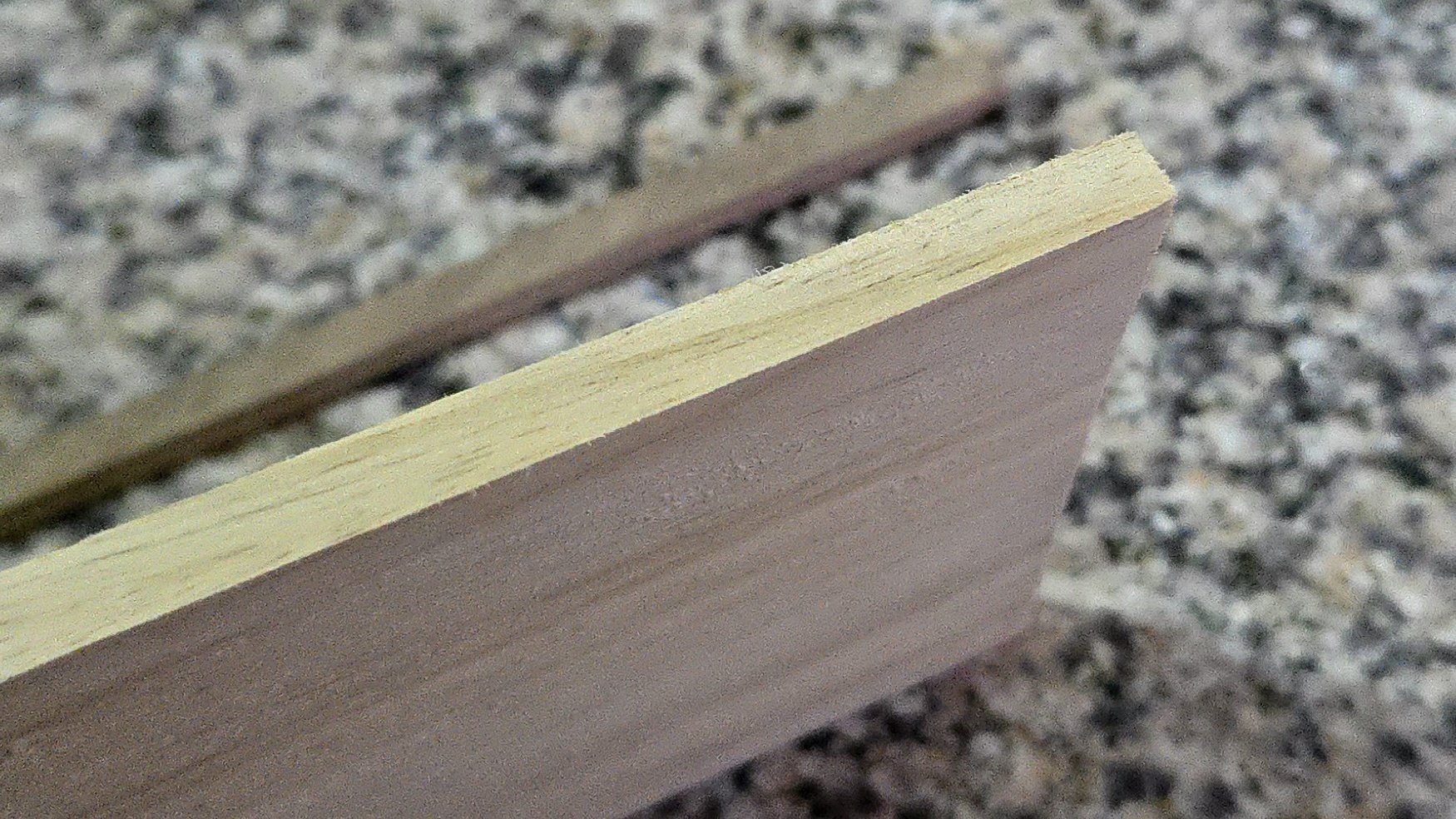
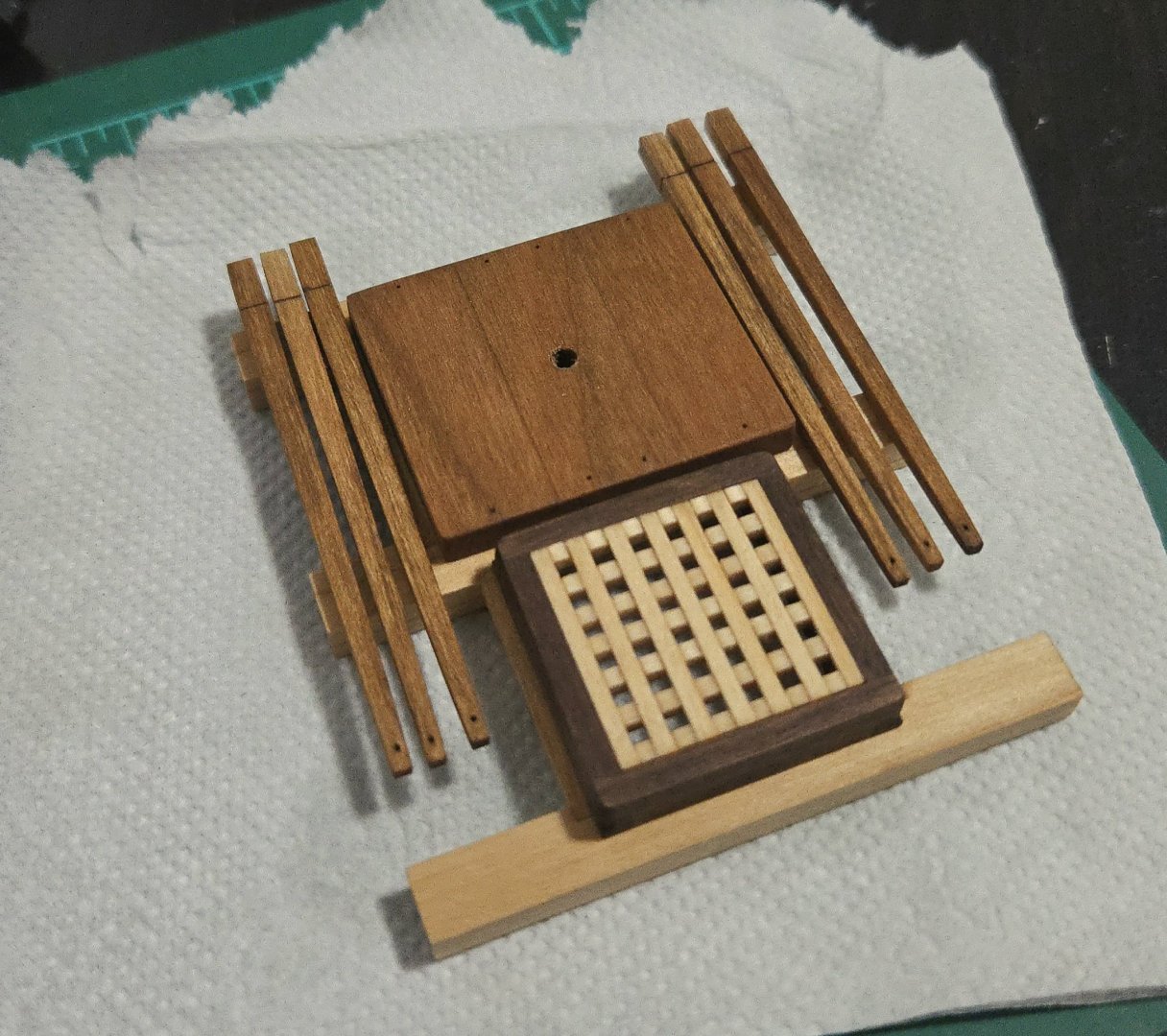
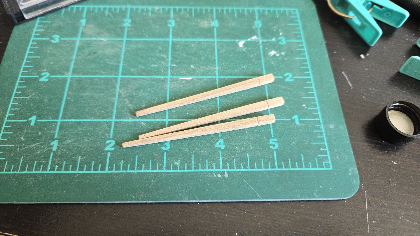
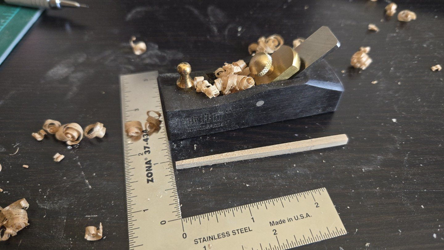
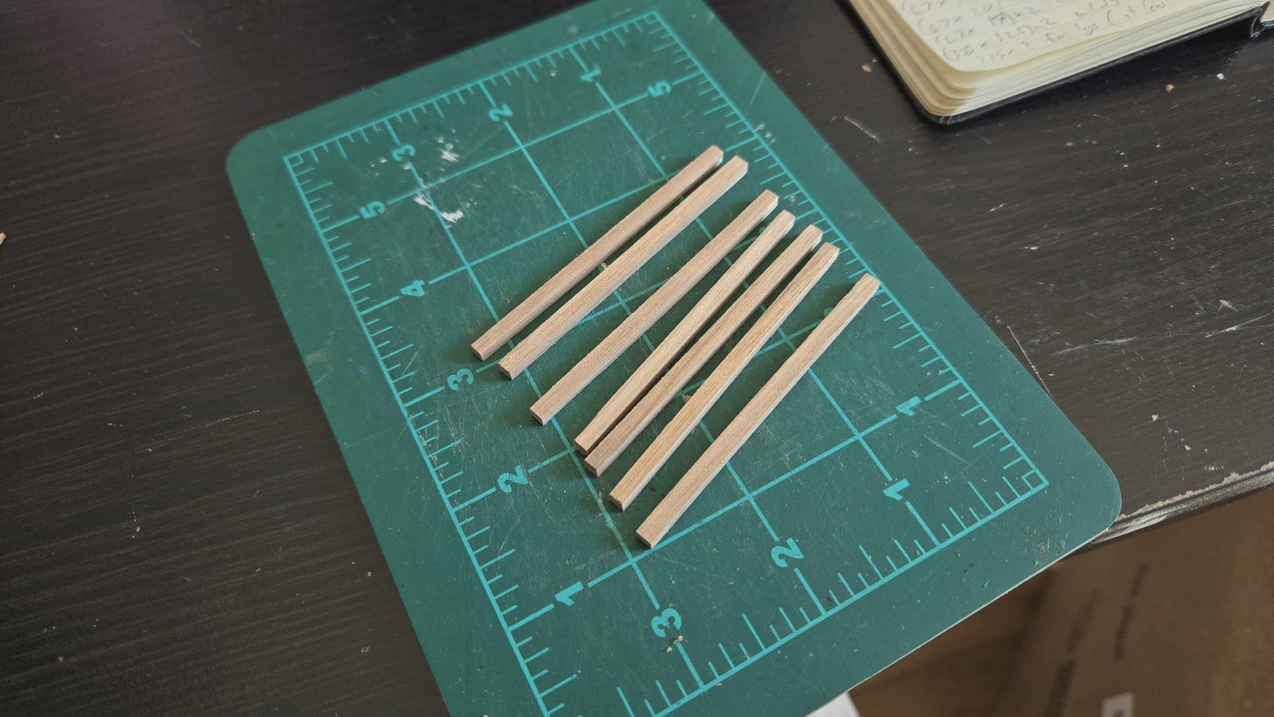
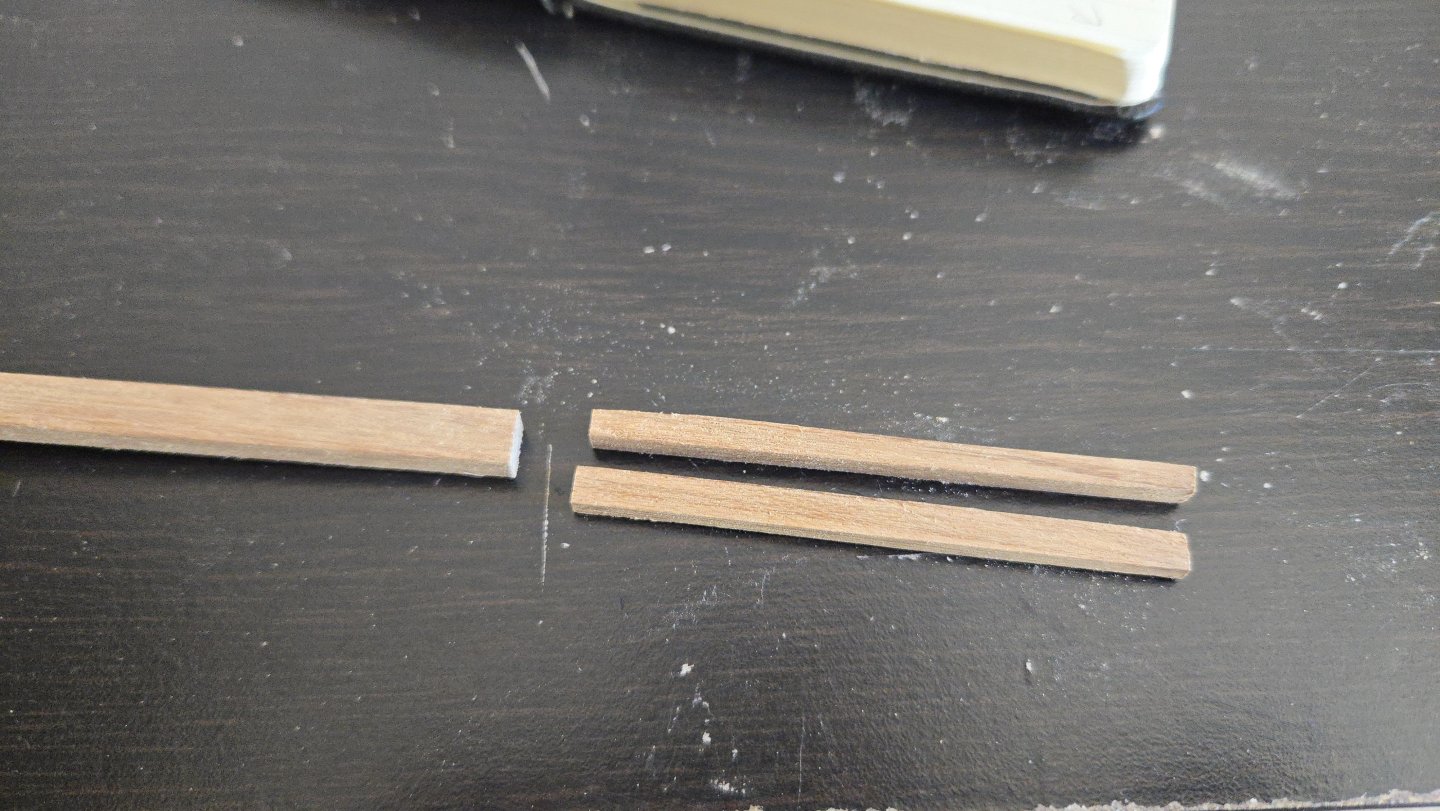
I'm back in Mexico City and was able to do some modeling today. The capstan itself will have to wait a bit, as the manzanillo wood needs some time to acclimate to the different climate. While Veracruz was around 80% humidity, Mexico City is currently around 30%, so quite different. Originally I just had the manzanillo boards stacked up, but I realized that the top boards were the only ones really drying (and only on one side, which was causing warping, as seen below. I've now stickered and stacked all the boards, hopefully they flatten out as they finish drying on all sides. In contrast, the xochicuahuitl strips were thin enough that they don't seem to need extra drying, so I began making the capstan bars. First I cut a little overlength and split a length of the strip. I initially tried sawing down into the wood, but I soon realized that xochicuahuitl is very soft and actually easier to cut with repeated passes with a knife. I screwed up on one cut, so ended up with a single extra bar blank. Once split, I used my mini plane to square up all bars in the proper dimension. I found that the xochicuahuitl planed decently, although it produced a lot of dust. It also smelled very pleasant when cut--I thought slightly peppery, my wife thought it was a Christmas-like smell. I then planed in the tapers. The amount of dust produced even from planing is somewhat visible below. I then marked where to cut the shoulders to fit into the capstan holes, although I haven't cut these as I'll need to fit them to the holes, and drilled the small hole at the end of the bar. Finally, I applied linseed oil to the bar (except for at the end to be cut). With finish applied, the xochicuahuitl took on a nice reddish color. It's slightly lighter than I thought it would be, but will look nice on the model, being similar in color to the cherry capstan base. Overall the xochicuahuitl is decent to work and beautiful, but soft and with pronounced grain and figuring that limits its utility in modeling.


- 32 replies
-
- 10
-
-
- NRG Capstan
- NRG
- (and 1 more)
-
Thanks, Bryan! More stubborn than brave, I have to admit. I'm a little concerned about whether I'll ever be able to take this across the border, but that may be something to figure out later.
- 32 replies
-
- 4
-
-
- NRG Capstan
- NRG
- (and 1 more)
-
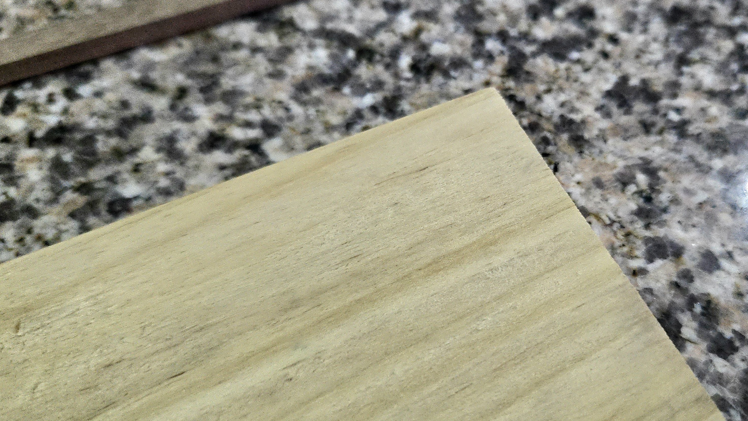
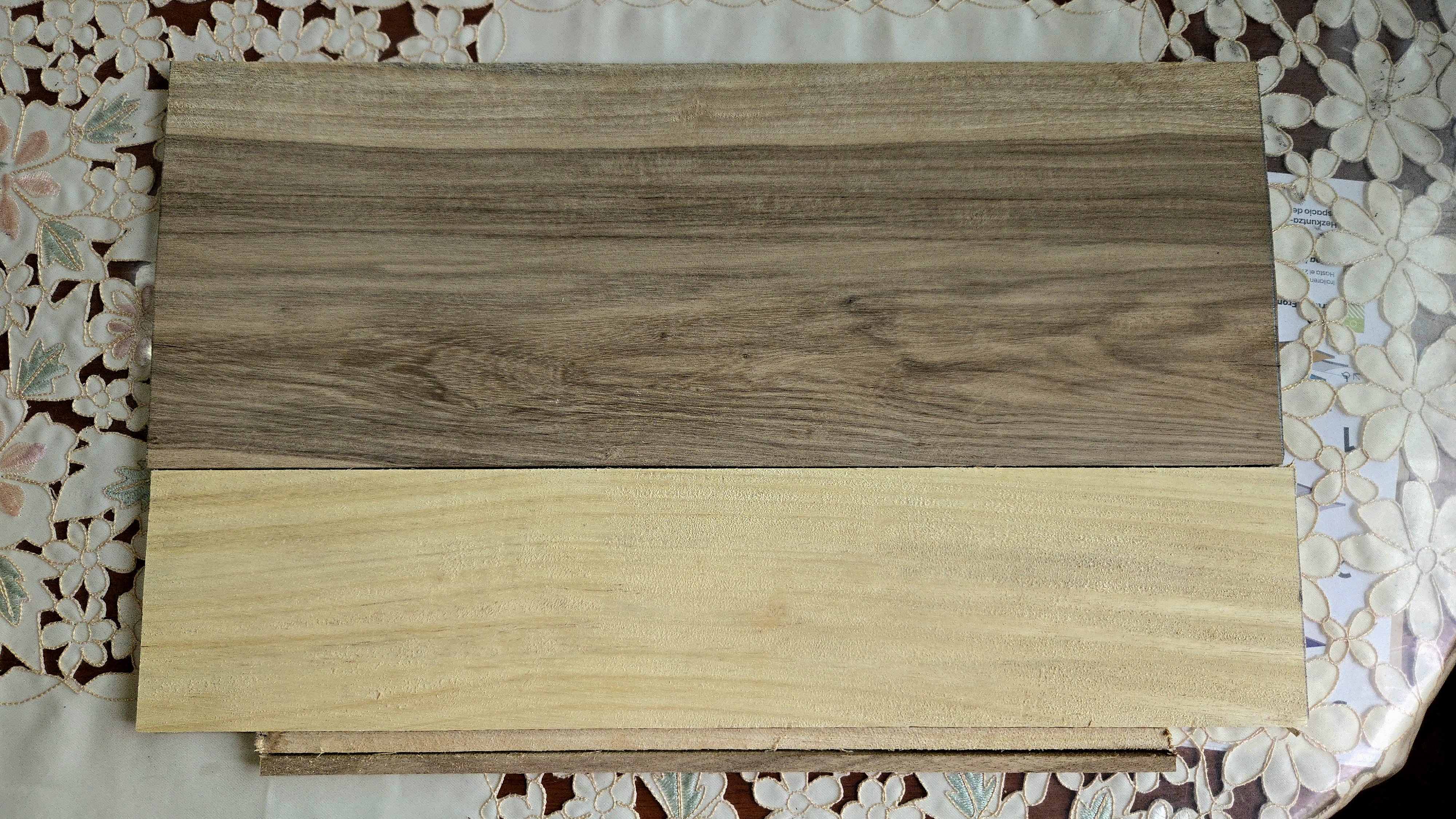
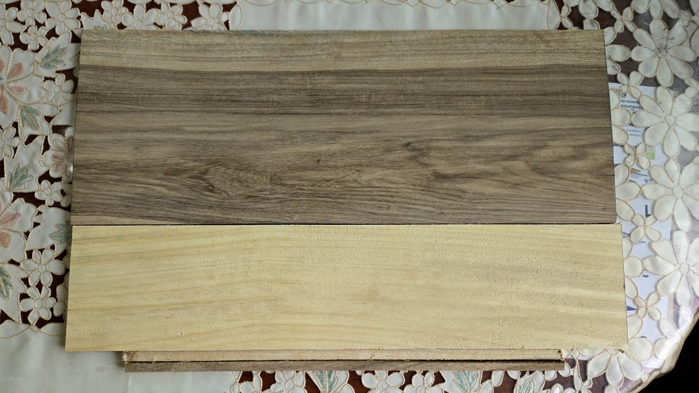
There's no build progress to report, as I've been focused on other things lately. But, as I mentioned in another post, I picked up some local hardwoods while traveling in Veracruz, mostly for other carpentry projects but with an eye to seeing if anything would be useful for modeling. I think I can use at least one type, maybe two, in this build, which would be a nice touch. As can be seen above, there are two main woods I was able to get (besides some cedar offcuts). The dark, heavily figured wood is Xochicuahuitl, which as far as I can tell is a kind of laurel. I was able to get some 1/4-inch planks, as well as some offcut strips. The grain pattern is probably too prominent for a lot of modeling tasks, but it does look quite nice. Today, as an experiment I sanded and cut a bit of one of the offcut strips. I found that, after dealing with the stringiness left on the edges from when it was sawed off, it sanded and cut pretty well, although there is some tearout if you try to cut against the grain. There's a good bit of color variation, too, but it's possible to choose lengths with a consistent color. It seems relatively soft, as far as woods go--certainly softer than walnut, maybe something similar to alder? It can be dented a bit with my thumbnail. I think the Xochicuahuitl strips will work well for making the capstan bars. I was hoping to make these of a dark wood to complement the coaming. The other wood was described to me as Manzanillo. It's a harder, yellowish wood with a fairly even grain (and some graying from moisture, which isn't a surprise given how humid and rainy Veracruz is). I have over a dozen small boards, 1/4 to 3/8-in thick. The big question was how workable this wood would be. As I mentioned elsewhere, after ordering it, I found that Manzanillo is also referred to as Manchineel, or "the tree of death." The sap is extremely poisonous, causing severe blisters on contact and reportedly being traditionally used to poison arrows, and the smoke can cause blindness (temporary but very painful for several days). As you can imagine, this was pretty disconcerting to read. The carpenter I was buying the wood from was surprised to hear this and said he'd never had any problems with it, showing furniture he had made with it, and I read that proper drying in the sun cures the sap and prevents ill effects, making the wood useable. Nonetheless, I was a little concerned about whether I'd be able to use the Manzanillo. After test-sanding some today outdoors, I can say that it should be quite useable. I did seem to detect a slight peppery odor when sanding, so I think I'll stick to sanding the Manzanillo outdoors with a mask (which I should probably be doing for all sanding anyway...), but despite coming into contact with the dust, I had no ill effects. Either the wood was properly dried and is indeed fully useable after doing so, or it's a different wood with the same, possibly local, name. In any case, it sanded and seems to hold an edge very well. With the more yellowish color, I'm thinking that this might be a good choice for the capstan itself. It should stand out a bit from the rest of the model and be close in color to the grating. The one potential hurdle is that I'll have to do a good bit of planing on all pieces, as my thinnest board is about 1/4‐in thick and I'll need to take it down to about half that for most parts of the barrel. I also will probably make the chocks and cap from a different wood--maybe basswood, maybe cherry or alder--to avoid having to plane down to thicknesses of 1/16‐in and 1/64-in, respectively. That's the plan, at least. Hopefully I'll be able to try it out once I'm back in Mexico City.


- 32 replies
-
- 10
-
-
- NRG Capstan
- NRG
- (and 1 more)
-
Looking forward to following along with this build! I'm very curious to see what you do to make it a working boat rather than a yacht.
-
Congratulations, great work! You've added a lot of personality to the kit.
- 167 replies
-
- 3
-

-
-
- Norwegian Sailing Pram
- Model Shipways
- (and 1 more)
-
Very nice work personalizing the tiller! As to your point about accuracy to a specific ship vs. accuracy to a generic type, I have to admit that I prefer the latter style. Figuring out the range of possibilities and choosing which option I want to depict and why seems more fun than trying to pin everything down to exactly how it was, at least at the moment. Who knows, though, maybe after a few more builds I'll change my mind.
- 167 replies
-
- 2
-
-
-
- Norwegian Sailing Pram
- Model Shipways
- (and 1 more)
-
Nice work! The pedestals definitely look better than the stand that came in the kit--it's a beautiful hull, so why cover it up? I personally would drill a small hole for a brass rod or something to stabilize the pedestal, but I don't know how difficult that will be with the mast already in place. My understanding is that it's not a huge model, so maybe just glue will be fine?