JacquesCousteau
-
Posts
1,390 -
Joined
-
Last visited
Content Type
Profiles
Forums
Gallery
Events
Everything posted by JacquesCousteau
-
 Fantastic job, very precise work!
 -
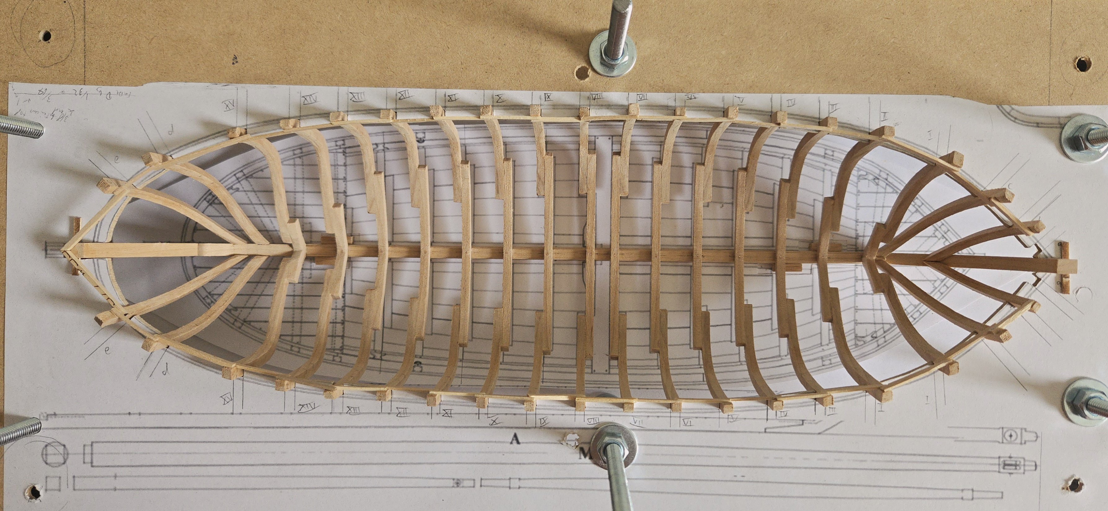
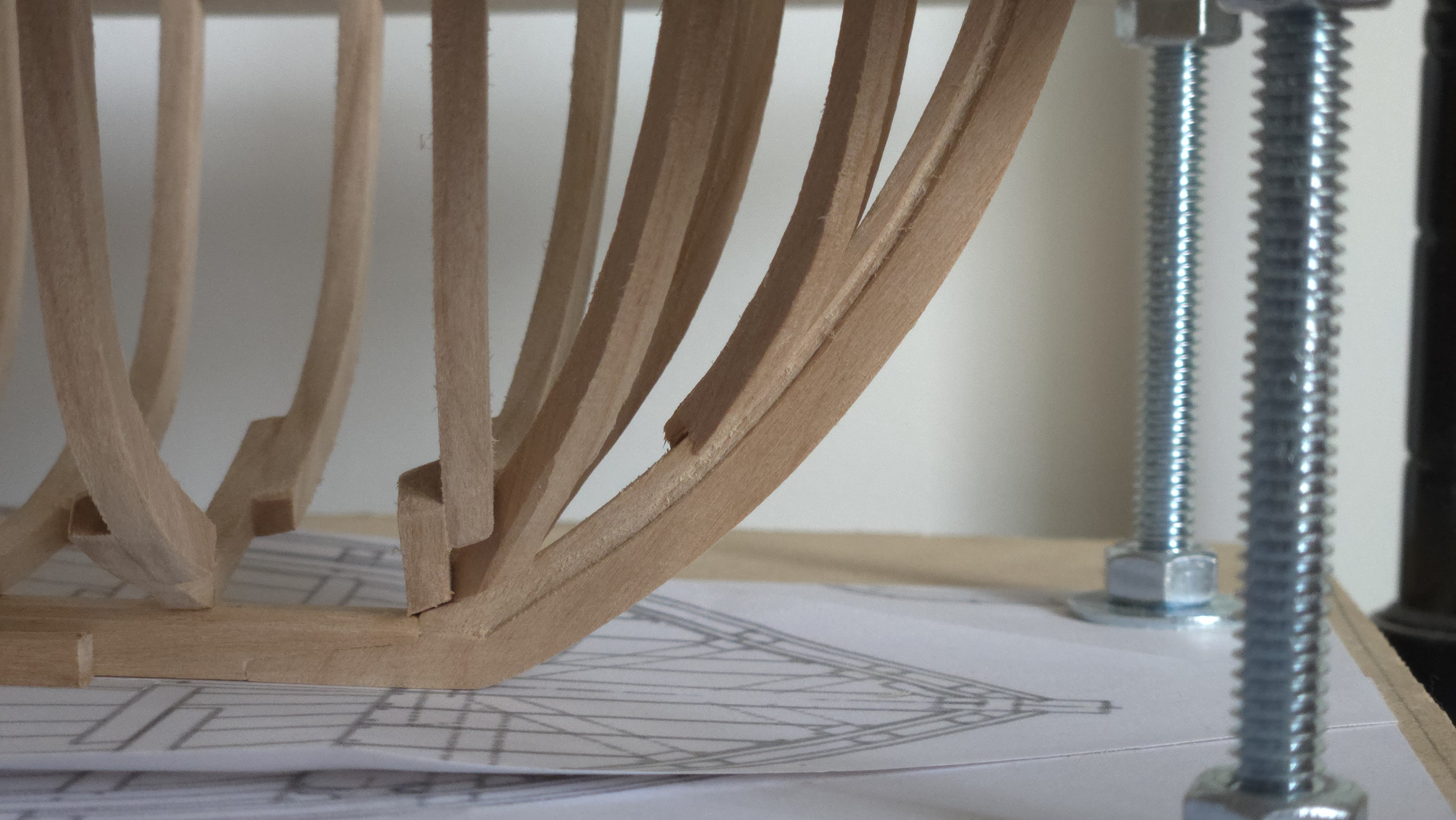
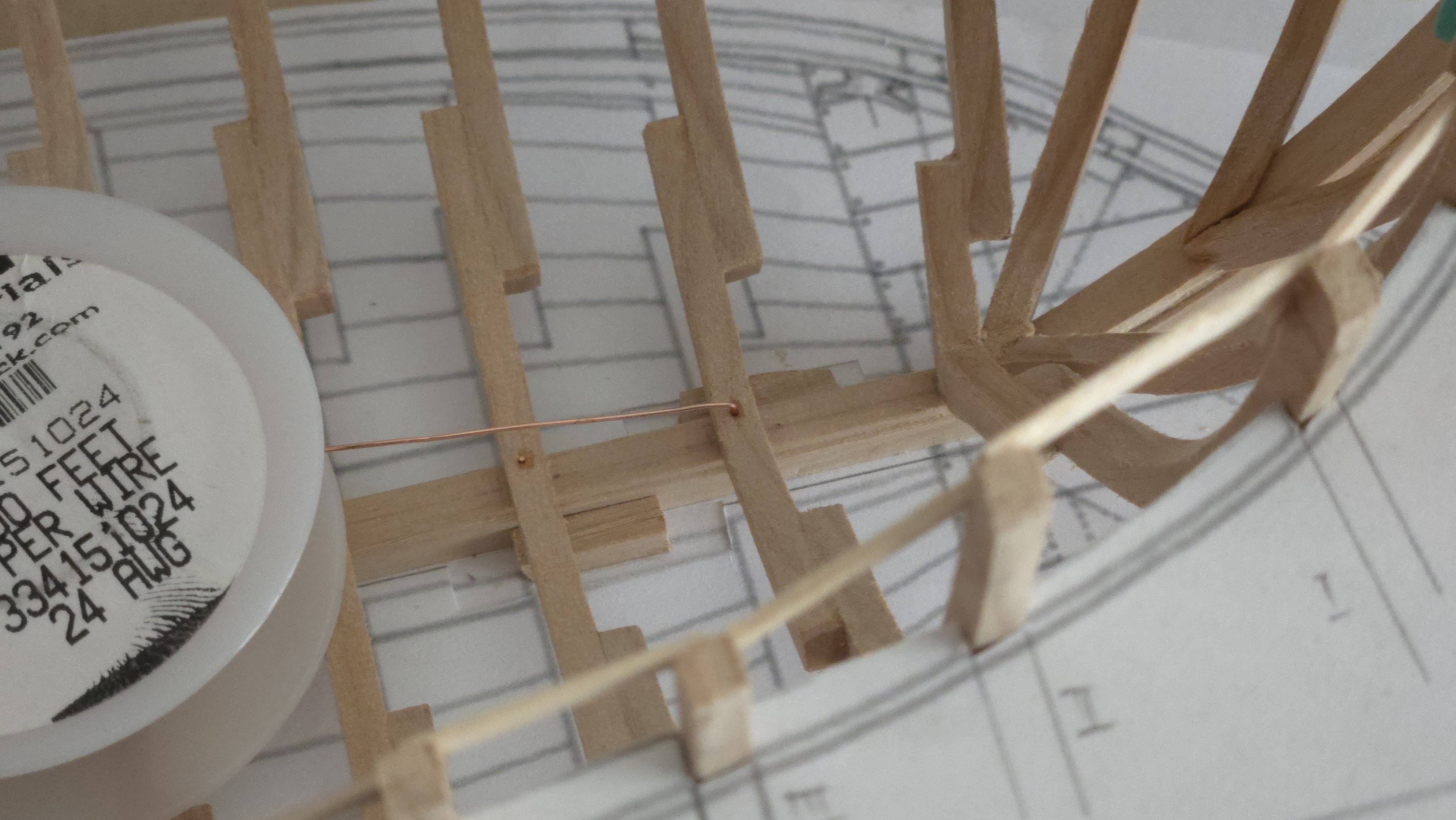
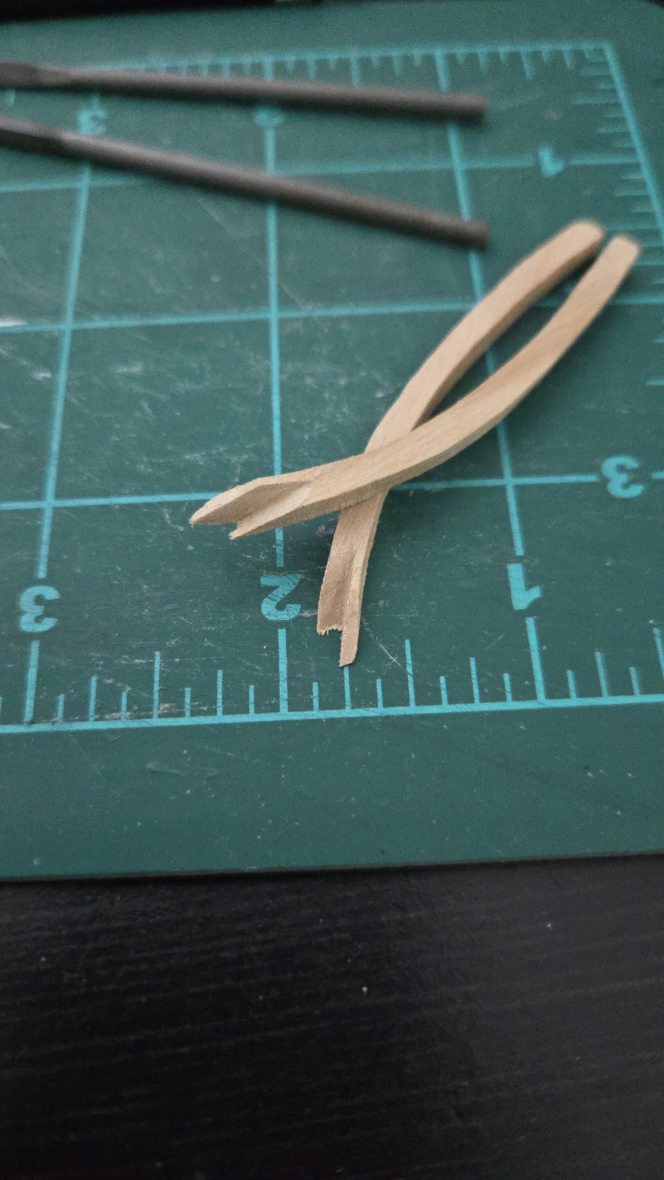
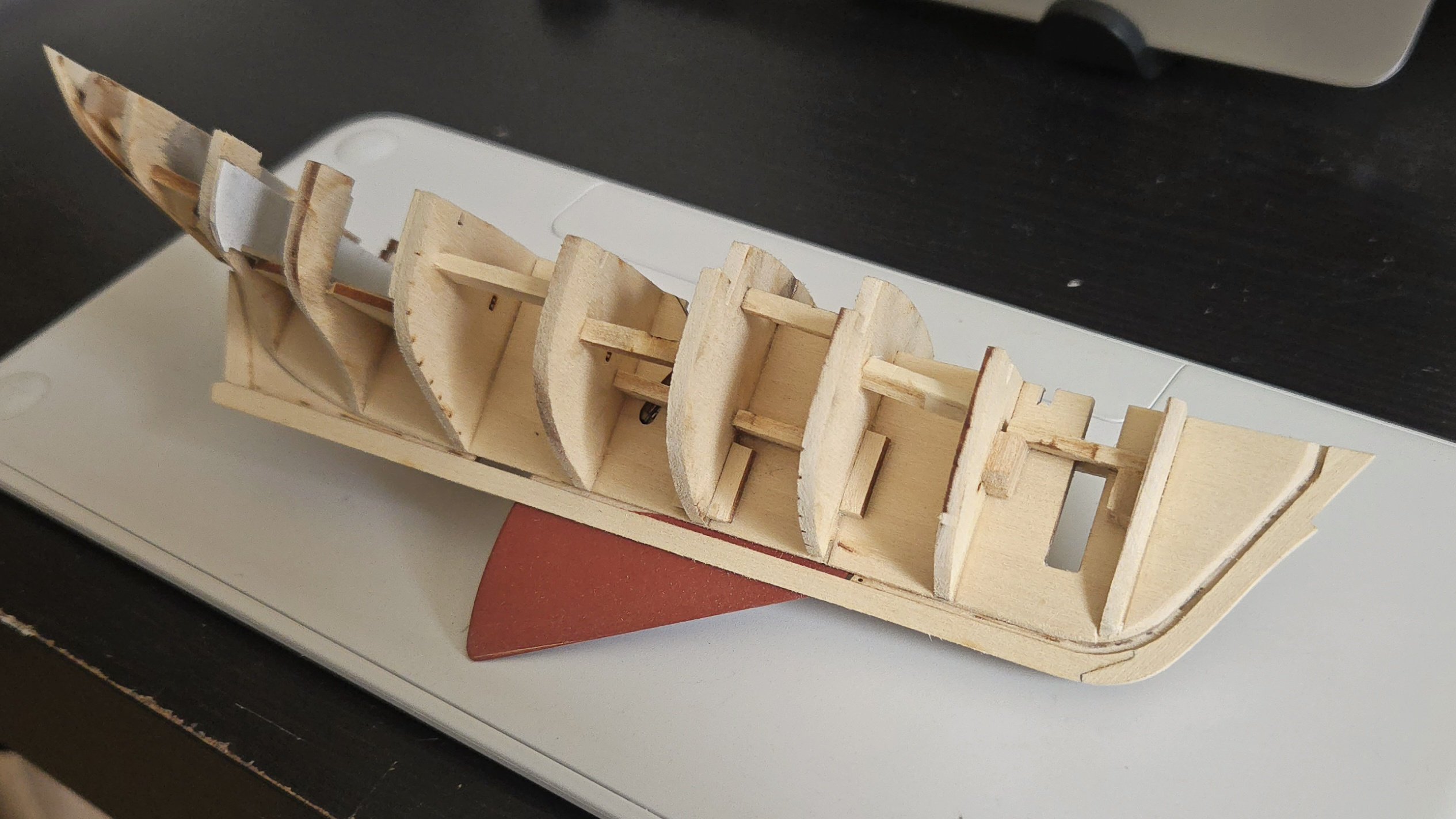
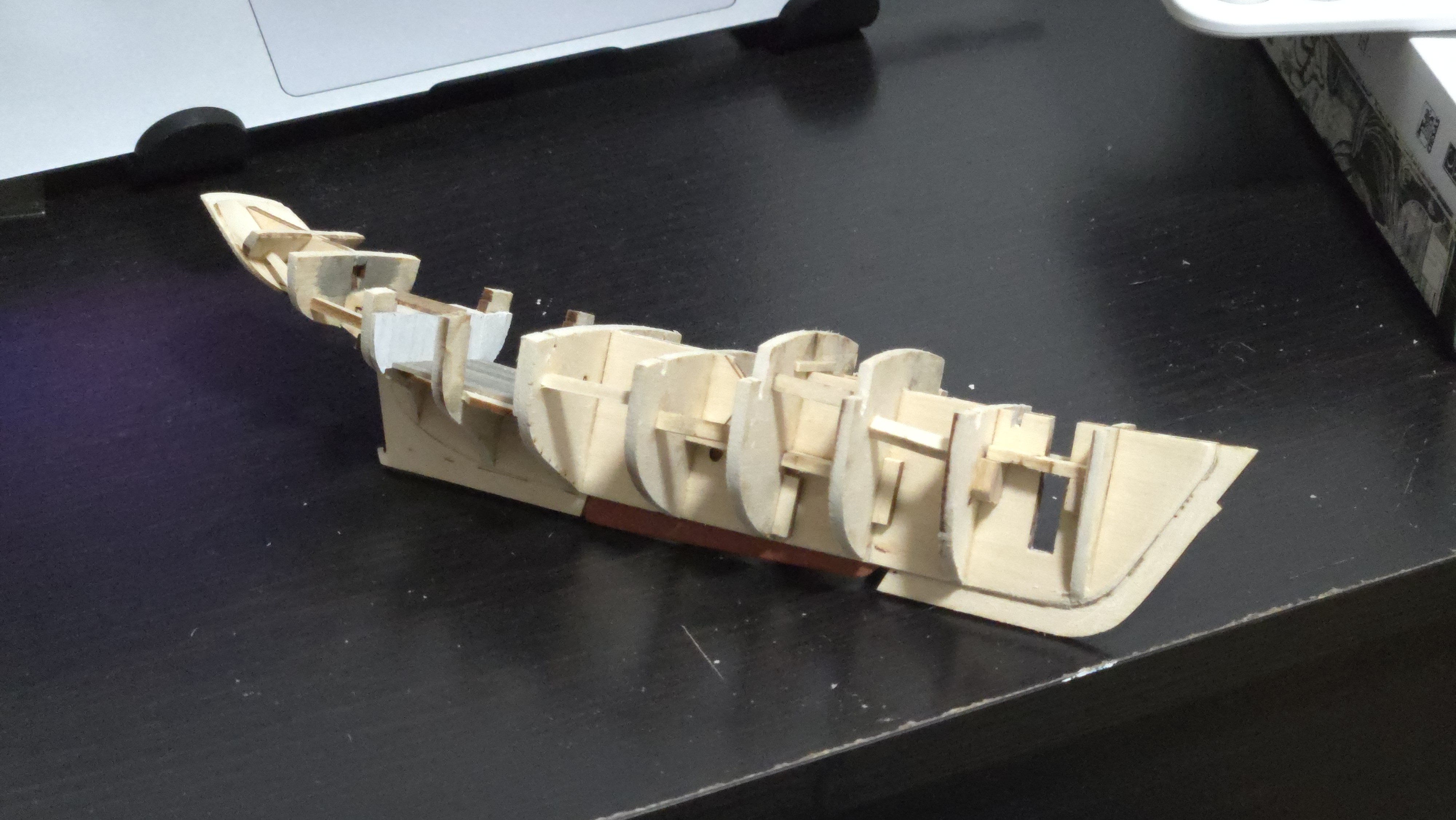
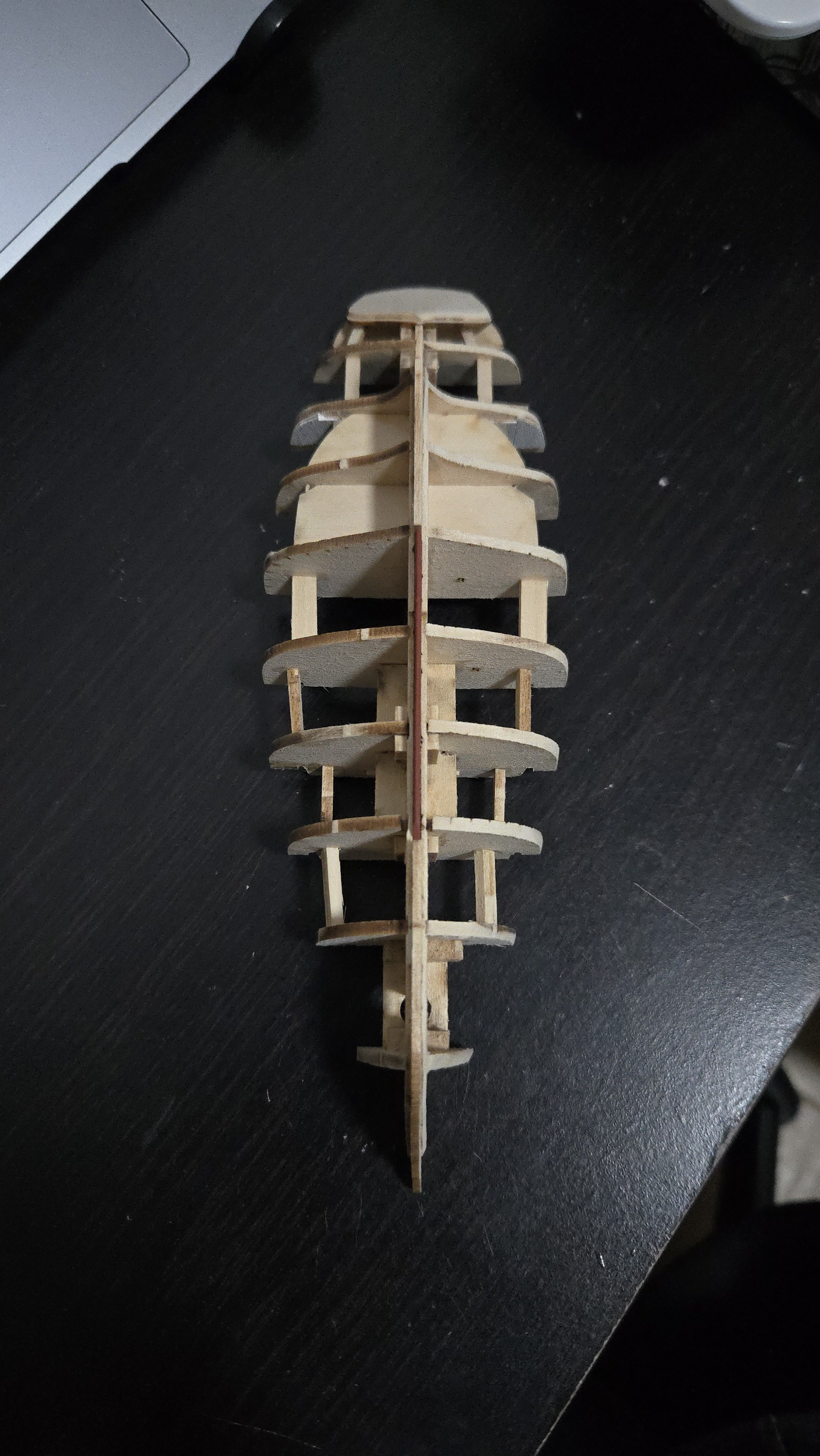
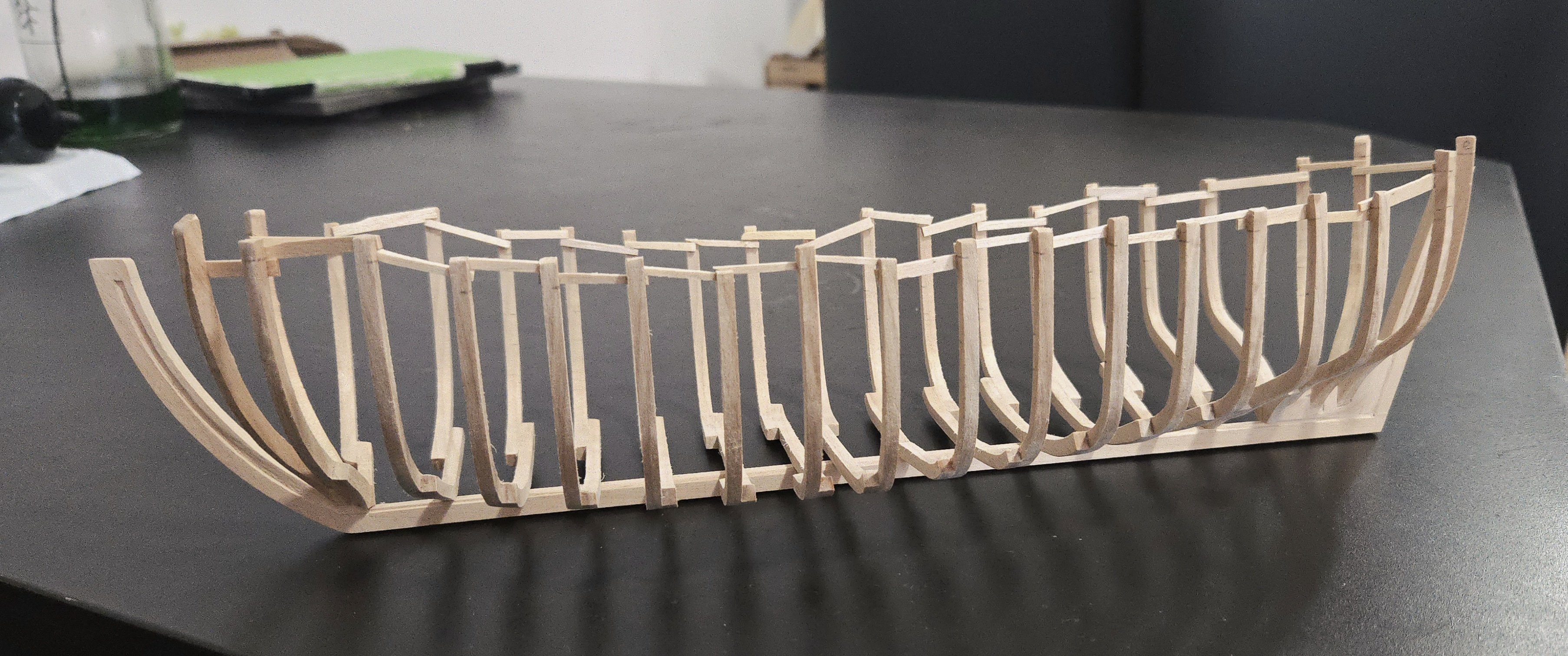
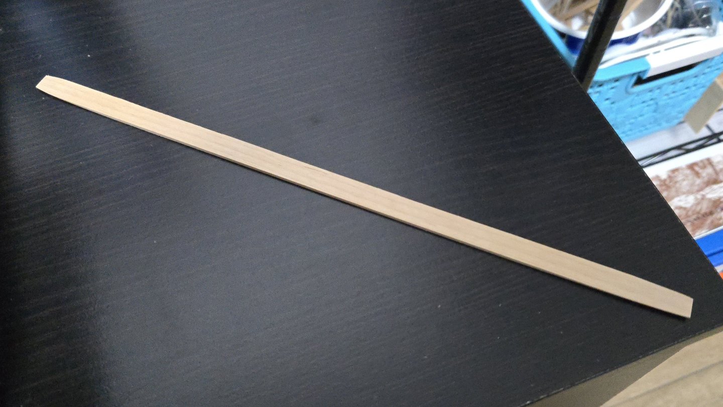
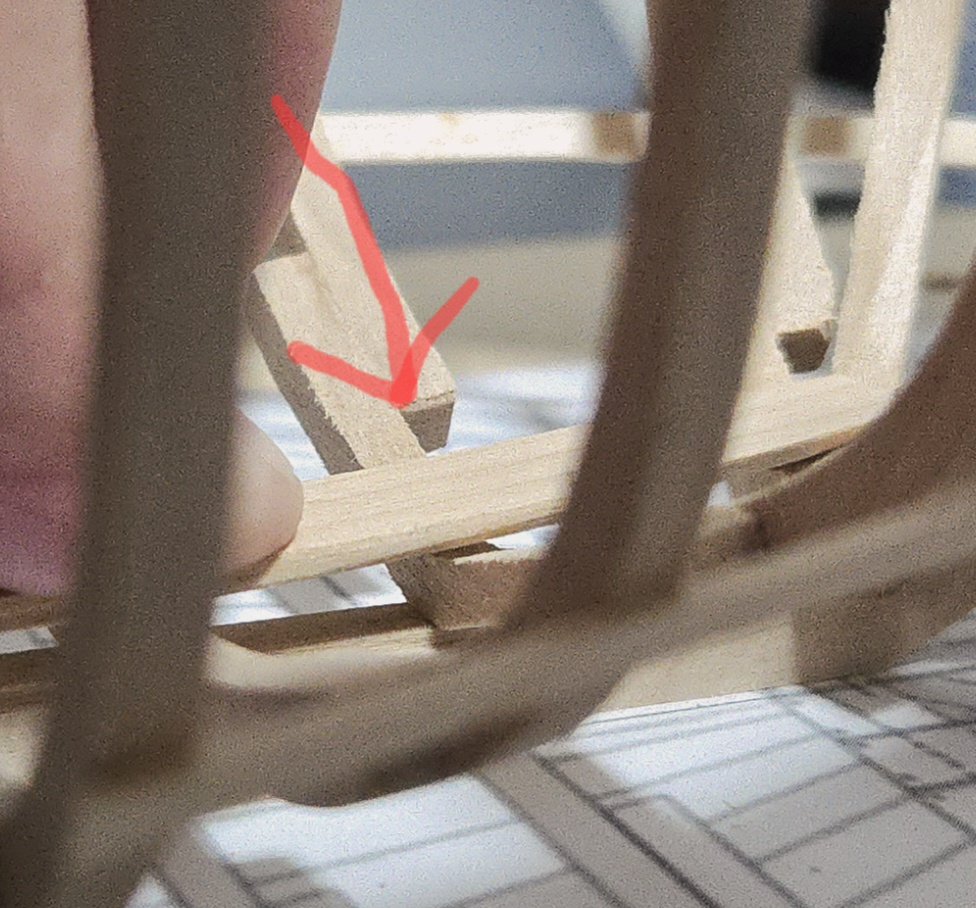
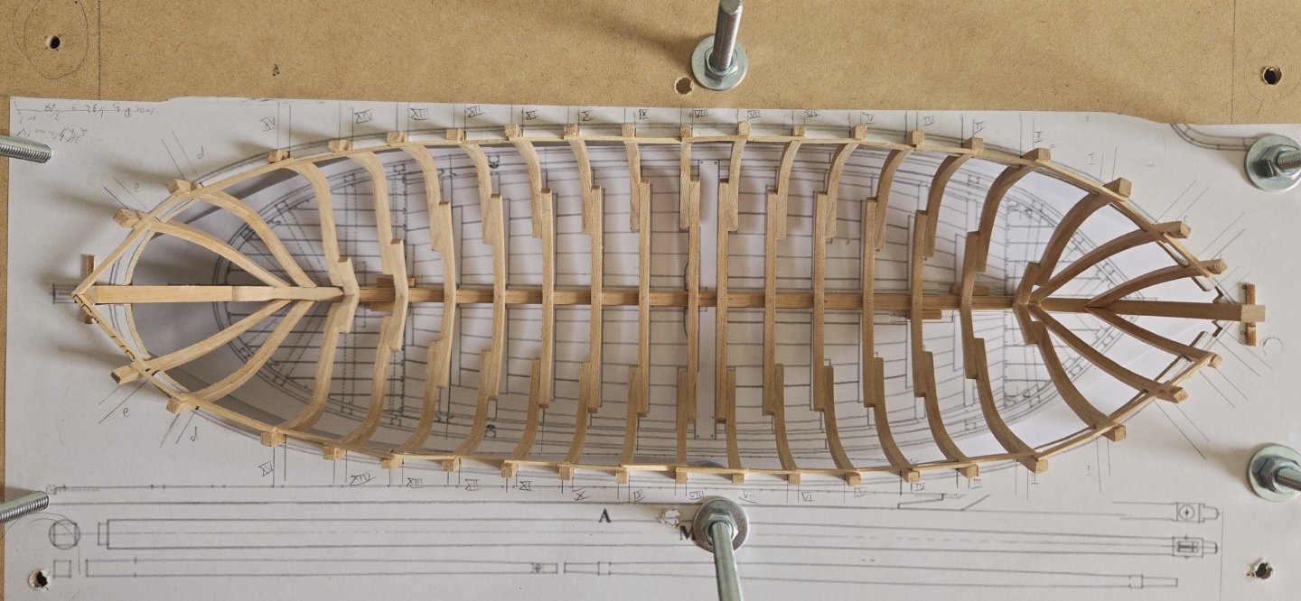
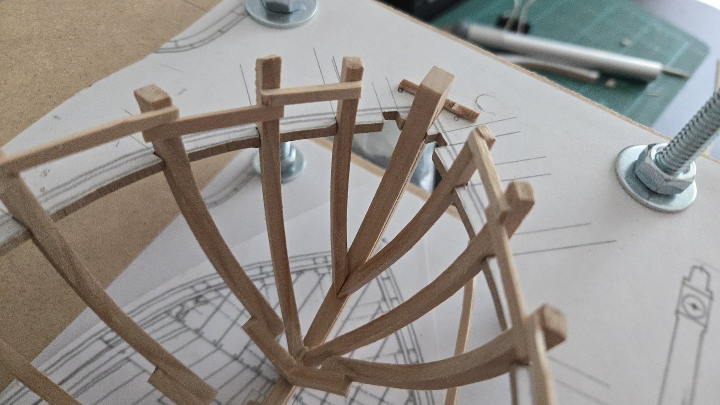
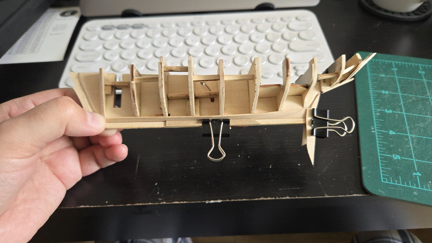
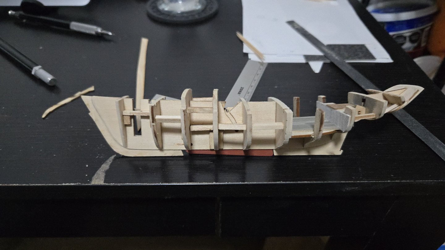
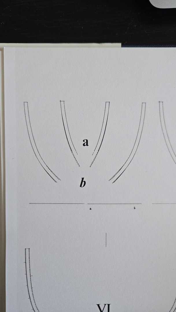
Thanks, Paul! I've found the time to make a bit more progress on this build. First, the keelson. This is just a long strip of wood, slightly tapered at both extremes. I'm making mine slightly longer than given on the plans to better cover the messy joints of cant frames C. Each end was also angled on the underside to better fit against the frames there. After a good bit of fairing, it fits smoothly across the frames, except for at frame 2 near the bow. I'm not sure if I cut the floor too thin here or what, but the keelson can't really be bent to fit onto this frame. I'm going to continue fairing frame 1, which I think is still too thick--the keelson is supposed to sweep up a bit at the ends, but maybe not quite this much--but I may have to add a support piece here. Second, cant frames B. As I've mentioned many, many times, the plans don't show the bottom ends of these. I had to trial-and-error my way into fitting them against the stem. One challenge is that the frames need to be on the aft side of the rabbet, but the frames are thicker than the relatively narrow ledge of the stem behind the rabbet. Checking photo logs of this model, I found that other builders have shaped these frames to fit onto the back of the stem--e.g., ending the frame in a notched joint rather than just a straight cut. I did one side first, constantly checking for fit and adjusting. It was a tricky cut to get right! By the time I had it right, the frame was a lot shorter than shown on the plans, as can be seen below (the parts were cut overlength, but the ends given by the plans are marked in pencil). Eventually I got both cut to shape. And I glued them in place. The joint with the stem didn't turn out quite perfect, but it should be stable enough and will be covered by the foredeck. Finally, I decided to pin the frames to the keel with a bit of copper wire and super glue, in order to strengthen the small butt joint there. It was tricky to push the wire all the way down into the holes because it easily bent and it was hard to get a grip to push it down, although it got easier once I started bending the wire at 90 degrees just above the length of the pin so that I could push down on the bend instead. Once all the pins were in, I was able to file them flush. I finally got to use the riffler file set I bought a while ago for this. Here's the current state of the build: Next, I need to add the last frames, cant frames A (which are basically hawse timbers or knightheads on either side of the stem). Given the highly acute angle where they meet the stem, these will be another challenge to shape.


- 141 replies
-
- 13
-

-

-
- ancre
- Bateau de Lanveoc
- (and 2 more)
-
If I remember correctly, I added some scrap wood to the edges to keep the frame sections lined up and tightly held in position.
- 46 replies
-
- 2
-
-
- Dory
- Lowell Grand Banks Dory
- (and 3 more)
-
I have no idea about this kit in particular, but it's pretty common for wooden boat kits to require a good bit of shaping to get everything lined up. One of the advantages of wood is that it's pretty easy to shape and, if there's a mistake, to glue back together. The model's coming along great!
-
Best of luck! Using a flexible sanding stick can be helpful for sanding several bulkheads simultaneously, which can really help keep them fair.
-
To be honest, I think you're going to have a hard time getting a satisfactory second planking with the first layer like this. There are a lot of large gaps and general unevenness. Getting a decent second layer requires a smooth first layer. There would be a lot of very tedious filling and sanding required at the moment to get to that point, and it would be quite challenging. The area over the square cutout at bulkhead 3, for instance, will be very hard to plank over without having an incongruous flat spot there. From the photos, it looks like the bulkheads weren't faired enough, which explains the gaps and probably the space between false deck and planking at the bow. You should be able to run a batten (a thin strip of flexible wood) over the bulkheads, at every point in the hull, such that it touches all of them evenly without bulges or spaces. Especially near the bow and stern, this usually means substantially beveling the bulkheads and taking off a surprising amount of material--usually there should only be a thin line of laser char left. There's an example of this in post #21 in my NRG Half-Hull build (and you can see the long slow process of fairing in the posts before that one): All of which is to say, I think you'll have a much easier time down the line if you remove this planking, fair the bulkheads more, and redo it. Following Mastini's advice to taper the planks is also a good one. Planking a hull is one of the hardest parts of ship modeling, so I wouldn't feel discouraged, but I think it's worth it to try to get it right to avoid frustrations down the line.
-
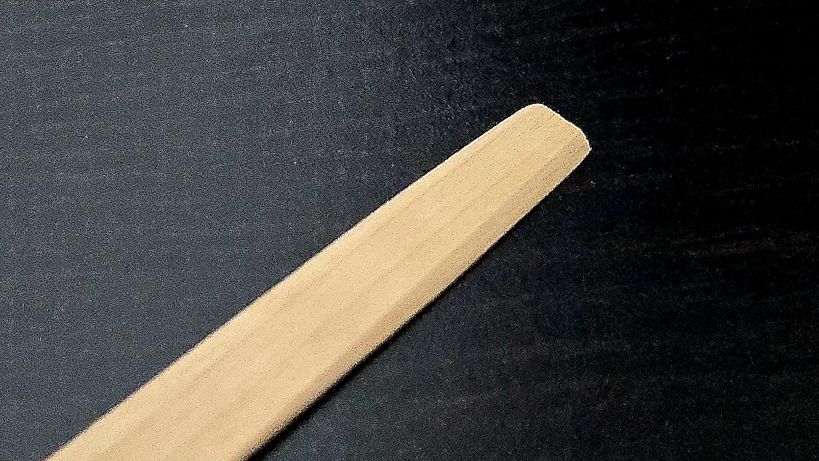
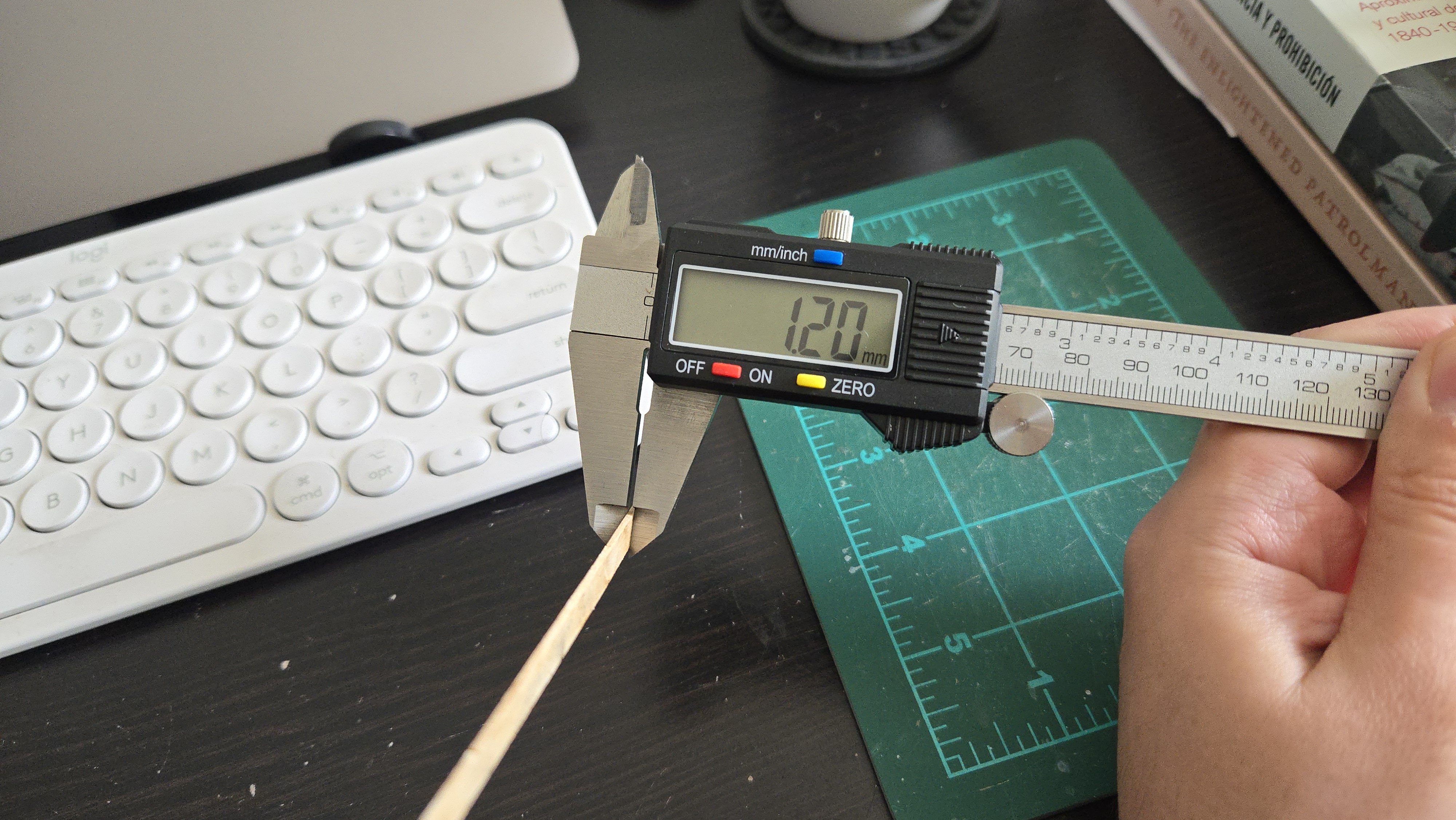
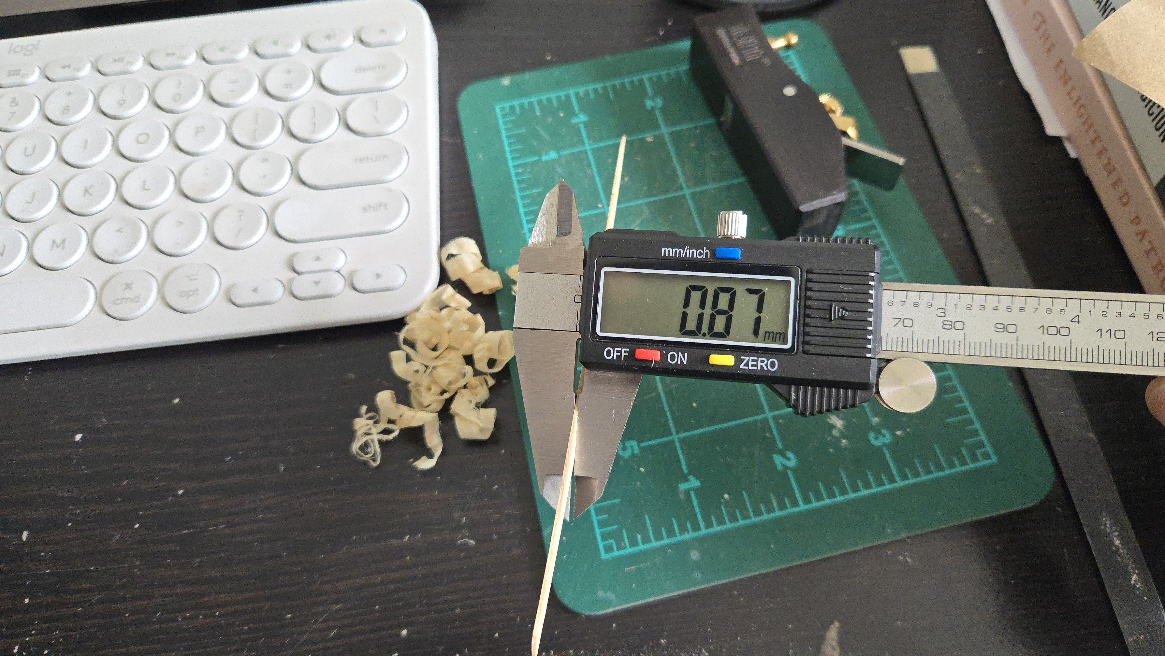
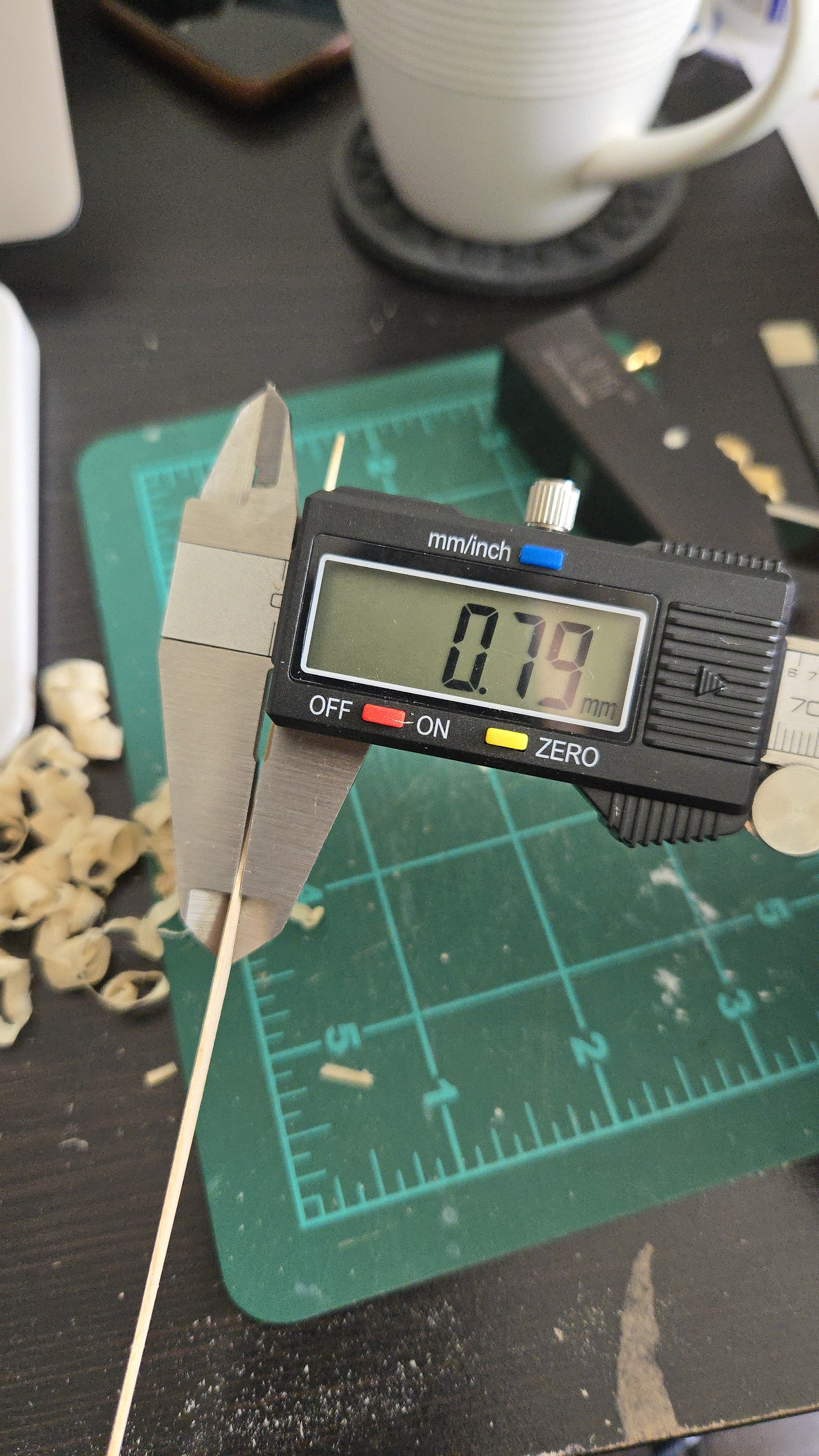
Thanks, @wefalck! The chamfering shouldn't be too bad, I think. Working out the run of the planking around the overhanging stern is a little tricky, though, and I'll have to take some time on it. I was curious to know whether the kit designed precut planks could be at all modified to serve as the basis for at least some of the lapstrake planks. This could in theory help a little with the complexity of the stern, and would also enable me to use the wood that's already been laser-cut. Looking around at images, it seems like most vessels had around 15-18 strakes of planking. (See below, for instance--granted, this is a deeper Friendship Sloop.) Source The kit design has 11 including an extra-wide sheer plank (which could be split in half or so to be about doubled). Both photos and kit are, of course, caravel planked. I'm assuming that a lapstrake planked vessel would probably use a similar number of planks, or perhaps very slightly fewer (as I'd imagine that it would be easier to use slightly wider planks rather than narrower ones, given the need to overlap planks. Taking a few preliminary measurements, it looks like the largest bulkhead measures around 2 inches. The precut planks are generally around 3/16-inch wide. So, if they were overlapped by, say, about 3/64‐inch, that would lead to around 15 strakes per side. Of course I need to do a lot more planning work, but I think I may be able to use the precut planks as the basis for at least some of the planks. I'll have to line off the hull and check how things look first, though. I thought I would try to dry-fit a precut garboard strake just to see what it would look like. I found it extremely difficult to bend into shape, even when soaked and heated. There's a pretty drastic twist from the stern to amidships, then another at the bow, over a fairly short distance of a little under 6 inches. I then checked with my digital calipers and found that the 1/32-inch thick basswood I had bought was actually 3/64 inches thick! (Dimensions shown in millimeters. 3/64 in = 1.19mm; 1/32 in = 0.79mm). I began planing it down to size with my mini-plane. This went pretty quickly, although I had to check repeatedly to make sure I wasn't angling the wood and creating an uneven thickness. Below: getting closer. And finally there! After being thinned, the plank bent easily into place even without being soaked or heated. Looking at it, my sense was that it looked a little too wide, especially aft. However, I soon realized that it would actually look narrower due to the overlap of the plank above. If I set the overlap for around 3/64 inch, it should look pretty good. It's also worth noting that, based on the photo below showing the stern of a Maine lapstrake sailing vessel, the Whistler, with a similar overhanging stern (although it's rather smaller than the vessel I'm modeling), it looks like having a wide garboard plank aft was entirely possible. In this case it's combined with a triangular deadwood piece, which is interesting to see although I don't think I'll be adding that. Source Anyway, I clearly have a lot more work to do on this, especially with lining out the hull and planning the chamfers, but even just fiddling around with the precut planks is helping me get a sense of how the strakes should run, especially at the stern.


-
Best of luck with the back! Your dory diorama project sounds like a great idea. There are plenty of paintings by Winslow Homer and Andrew Wyeth of dories drawn up on shore or in harbor that might serve as inspiration.
- 44 replies
-
- 1
-

-
- maine peapod
- peapod
- (and 4 more)
-
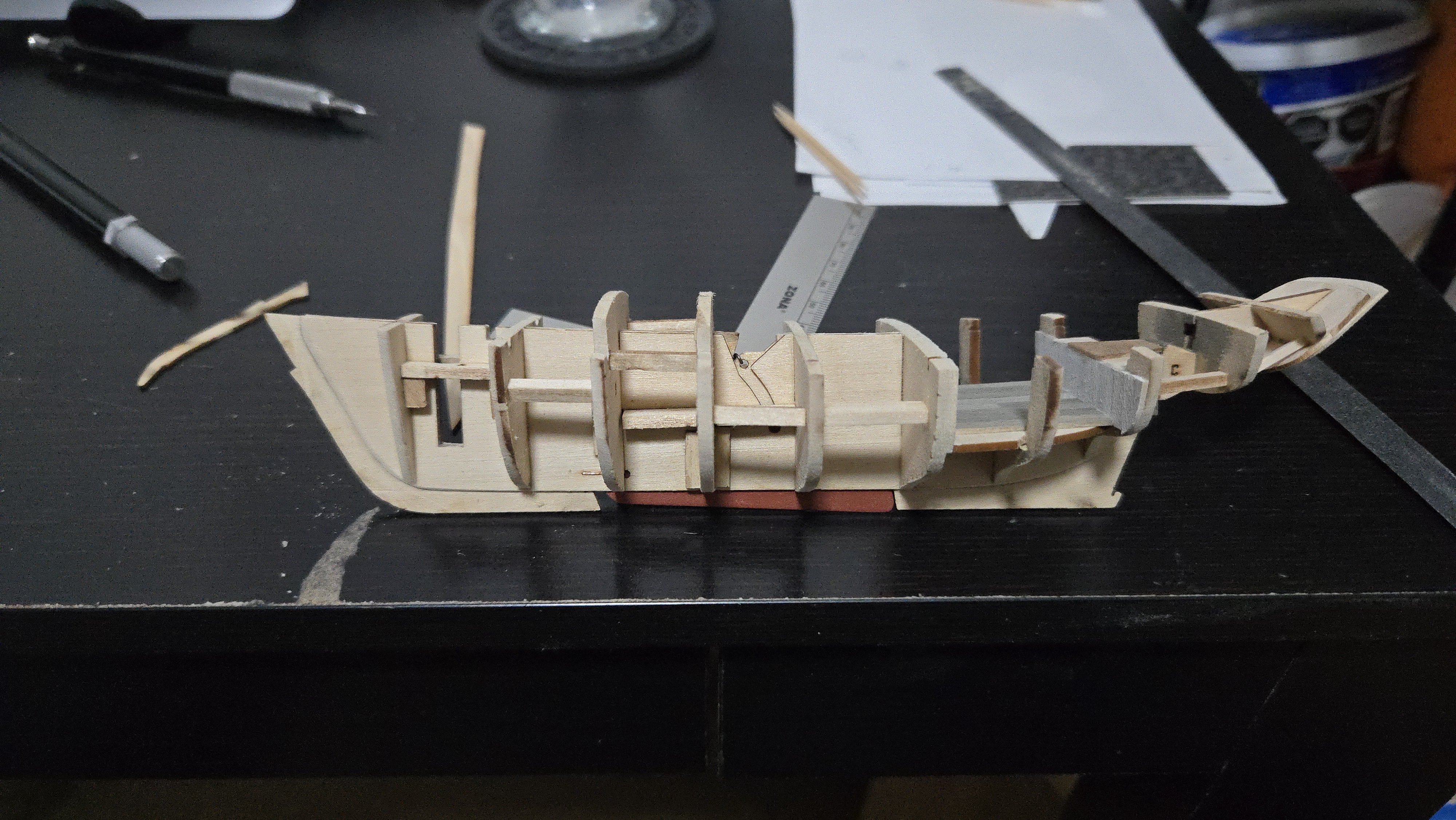
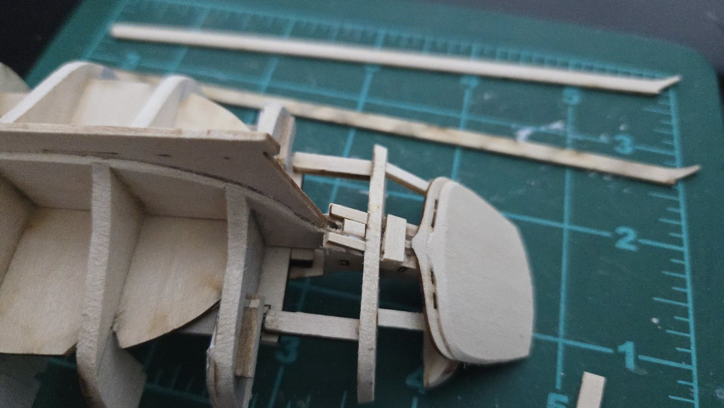
After a bit more work with the sanding sticks, both sides are now faired. This hull has been much, much easier to fair than my Lancha Chilota build was. The only real issue has been that I think I didn't quite get bulkhead 2 seated properly so it ended up being less sanded than the other bulkheads. I also realized that I needed to build up the area around and just aft of the opening for the rudder, as it was a bit low. I added some scrap and sanded it fair later. Next up, attaching the outer pieces of the keel, stem, and sternpost. The joint of the stem turned out nice and tight. It's good to see that my rescaling and conversion for laser cutting didn't ruin these parts! Next up, I'll be starting planking. This will be my main modification from the kit design*, as I'll be doing lapstrake instead of carvel planking. This will definitely be a challenge, and I'm looking at other build logs for inspiration. Druxey's Greenwich Hospital Barge log has some great information for lapstrake planking in a relatively small build. *I had almost tried to reshape the bow to do away with the beakhead and to be more vertical, but I realized that, besides causing difficulties in fairing the hull, it would also substantially reduce the area to affix the bowsprit. Modeling something like the Muscongus Bay sloop photos I've shared with plumb bows would probably be easier as a complete scratch build rather than a rescaled kit.


-
Very nice work, the hull lines really shine through! That Brazilian pine seems to work really well for planking, it looks a lot nicer than the pine I've been using for non-modeling purposes.
-
It's definitely an interesting hull shape. I have to wonder what purpose the sharply raked stern served.
- 50 replies
-
- 1
-
-
- Lady Isabella
- zulu
- (and 1 more)
-
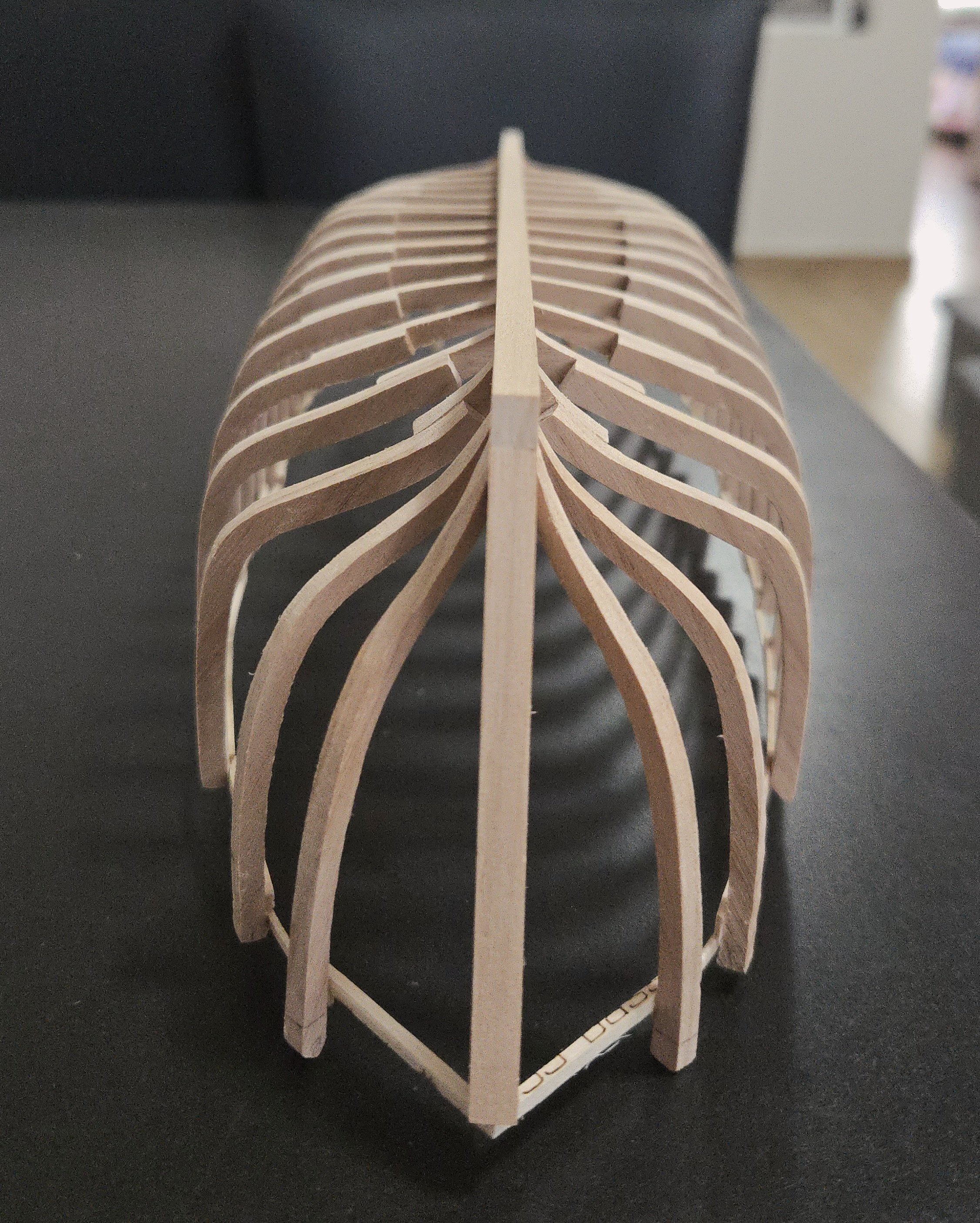
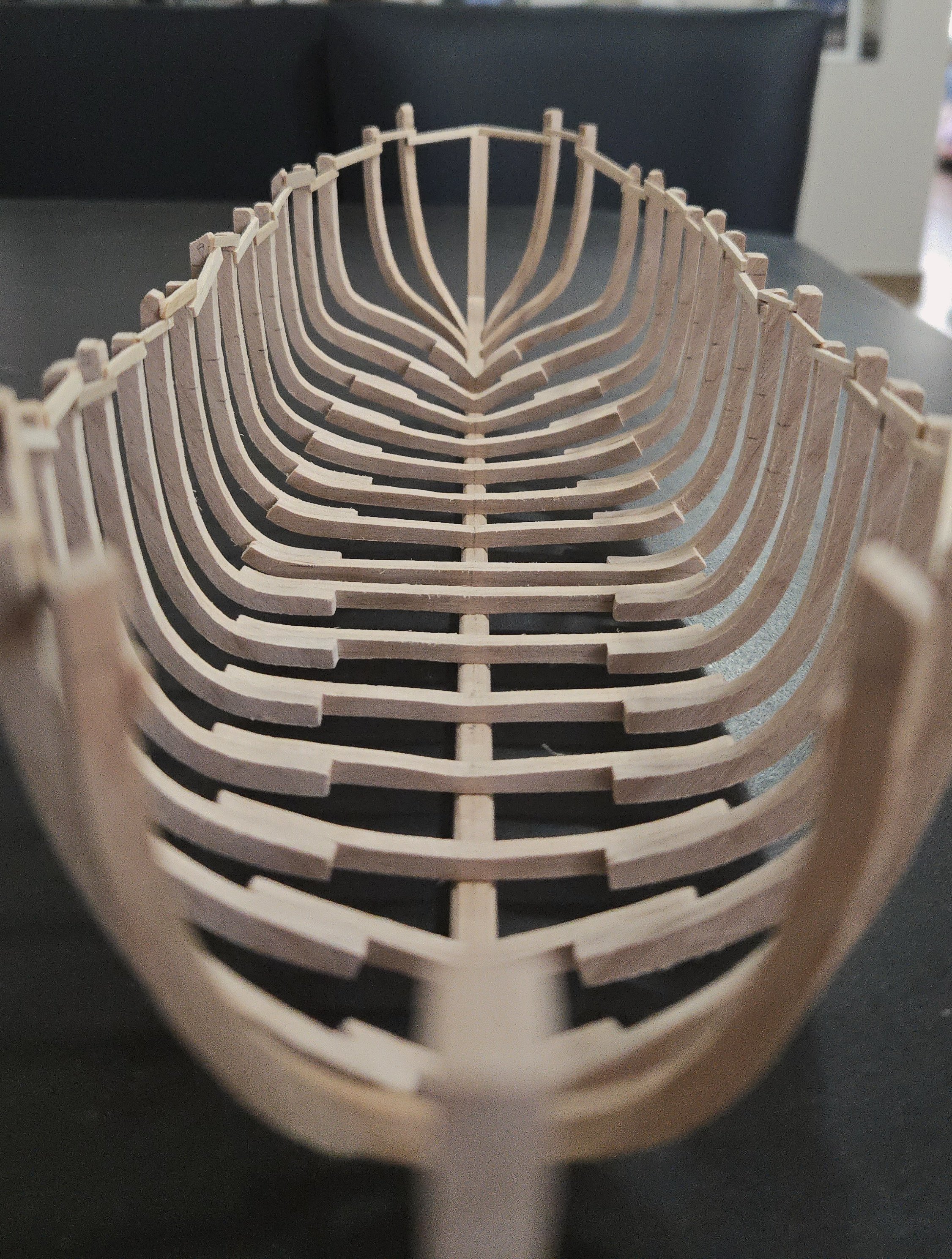
While my modeling time has mostly been focused on the Bateau build, I've progressed a bit. The next step is fairing the hull. The kit design would have you add the deck now to stiffen the hull for fairing, but I won't be adding the deck until much later so I can more easily build the cockpit. So, as the frames felt a bit fragile, I added supports between the bulkheads. I've also started fairing. My method for a small hull like this is to first use a batten to check which frames seem especially high at the top, middle abd bottom of the hull, taking notes on this. I then fair with a flexible sanding stick, and a curved sanding block in the hollow of the lower aft hull, giving special attention to the high frames. It's then a slow process of continuing sanding and checking fairness with a batten. By this point, I've gotten the starboard side and the deck mostly fair. Next up will be the port side, then I'll check both sides for evenness and final fairing.


-
Getting back on the horse....
JacquesCousteau replied to Sterling59's topic in New member Introductions
Welcome! The NRG Half-Hull is a great kit for learning planking, although definitely a bit challenging. I'd highly recommend checking out build logs, if you haven't. -
That's what I get for not zooming in more.... Still an excellent mug!
- 492 replies
-
- 2
-
-
- minesweeper
- Cape
- (and 1 more)
-
Very impressive! How did you manage to paint the seal? Is your brush made of a single bristle?
- 492 replies
-
- 2
-
-
- minesweeper
- Cape
- (and 1 more)
-
Beautiful work! The hull looks really sharp. On the mast step, I wonder if you could notch the bottom of the mast to fit around the keel? Depending on how wide those parts are, of course. It would at least secure the mast from side-to-side movement.
- 90 replies
-
- 2
-
-
-
- Friendship Sloop
- bluejacket shipcrafters
- (and 1 more)
-
Very nicely done, the model (and its case) looks great! It's definitely a unique kit, I love how it shows the internal structure of the vessel.
- 76 replies
-
- 1
-
-
- Pinas
- kolderstok
- (and 2 more)
-
Very cool project, I'm looking forward to following along!
-
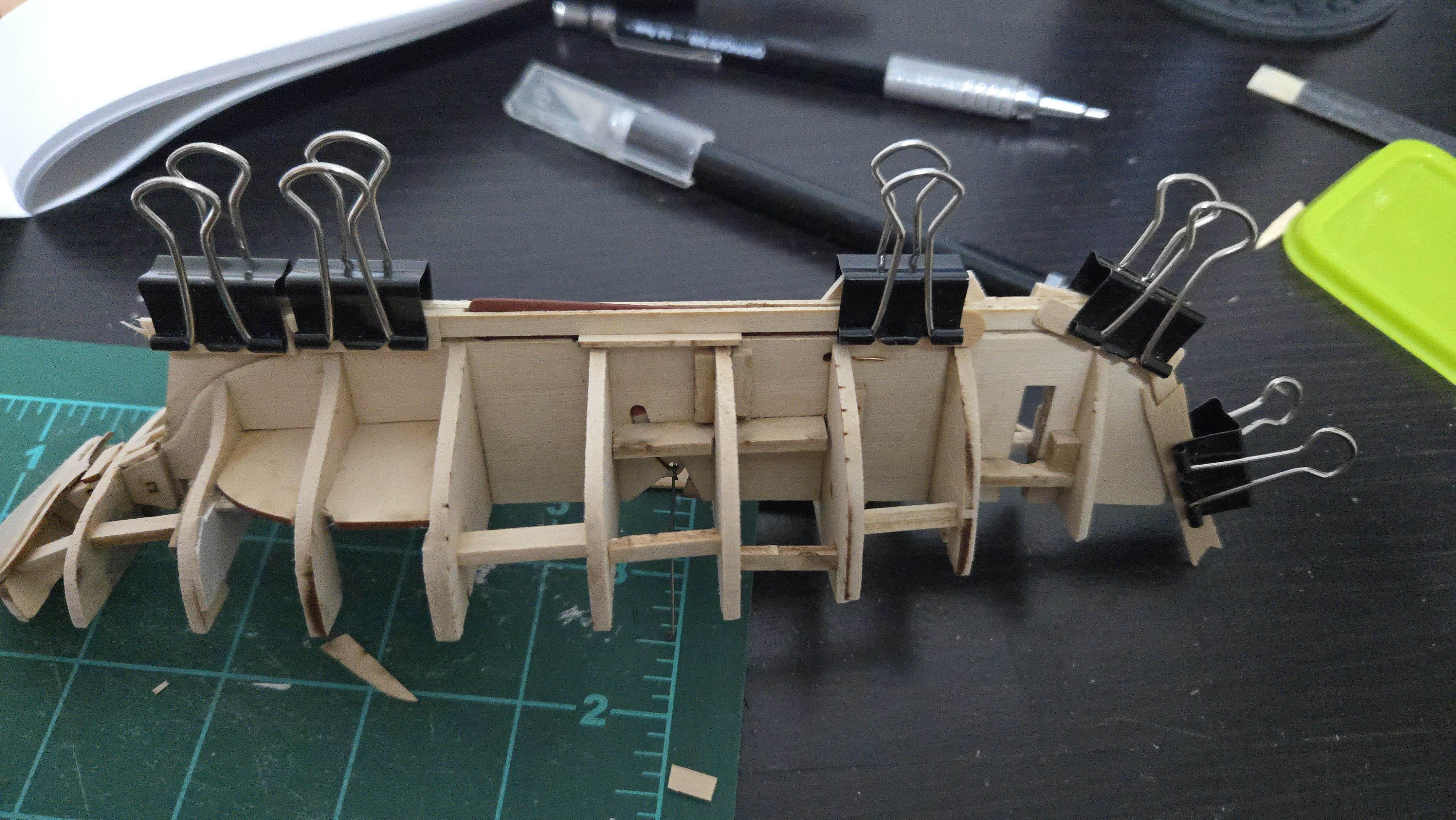
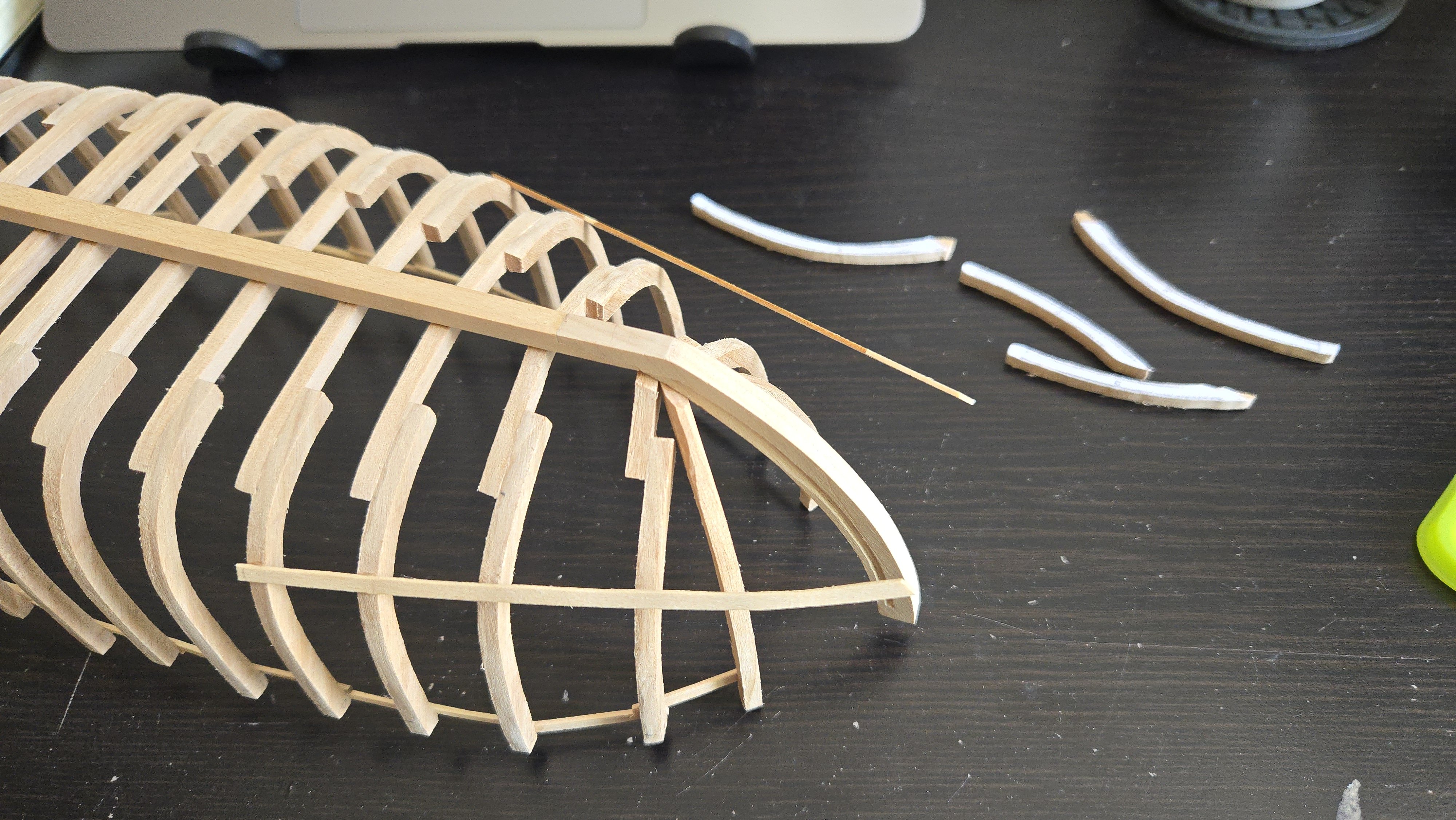
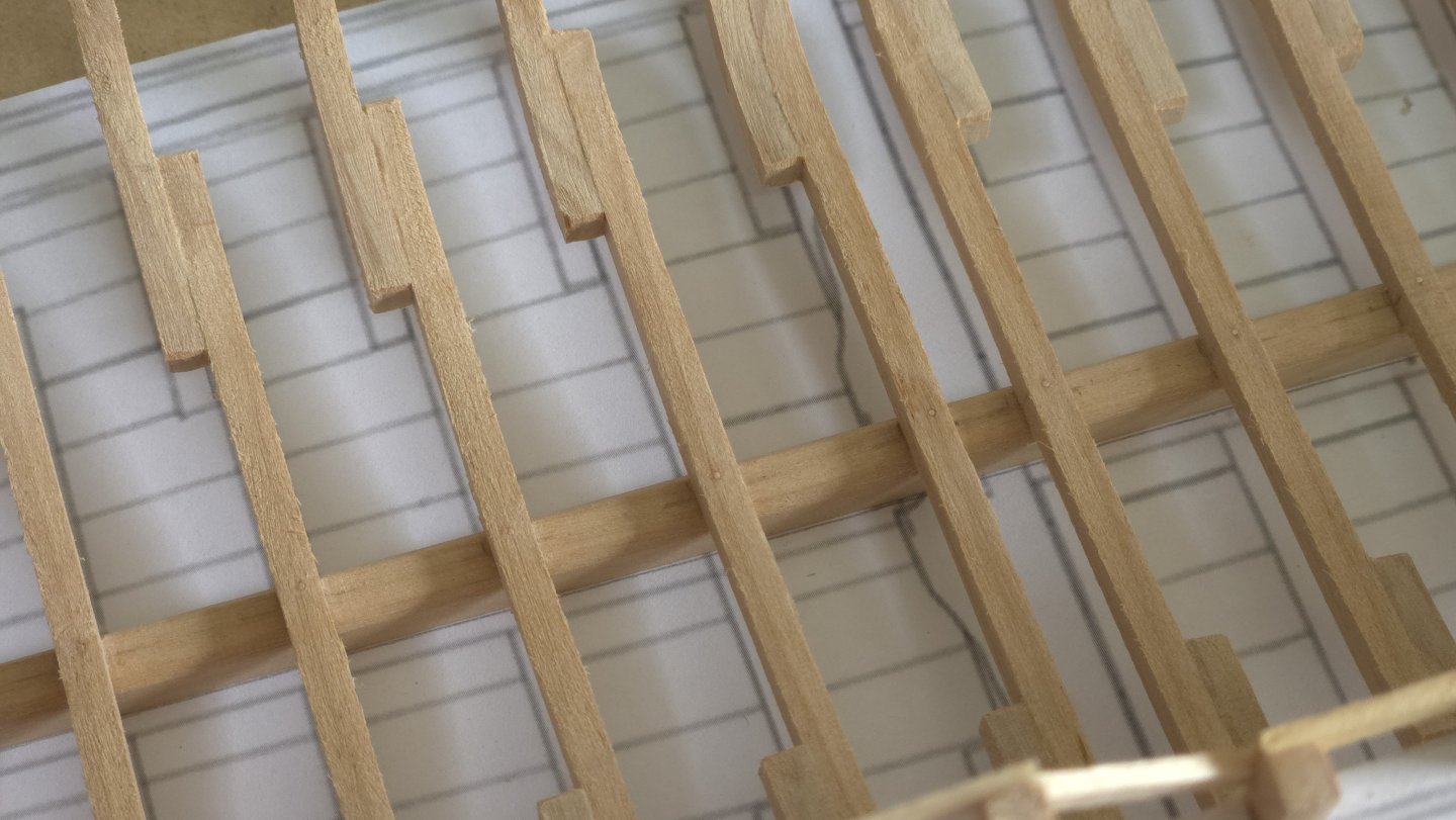
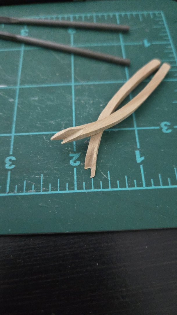
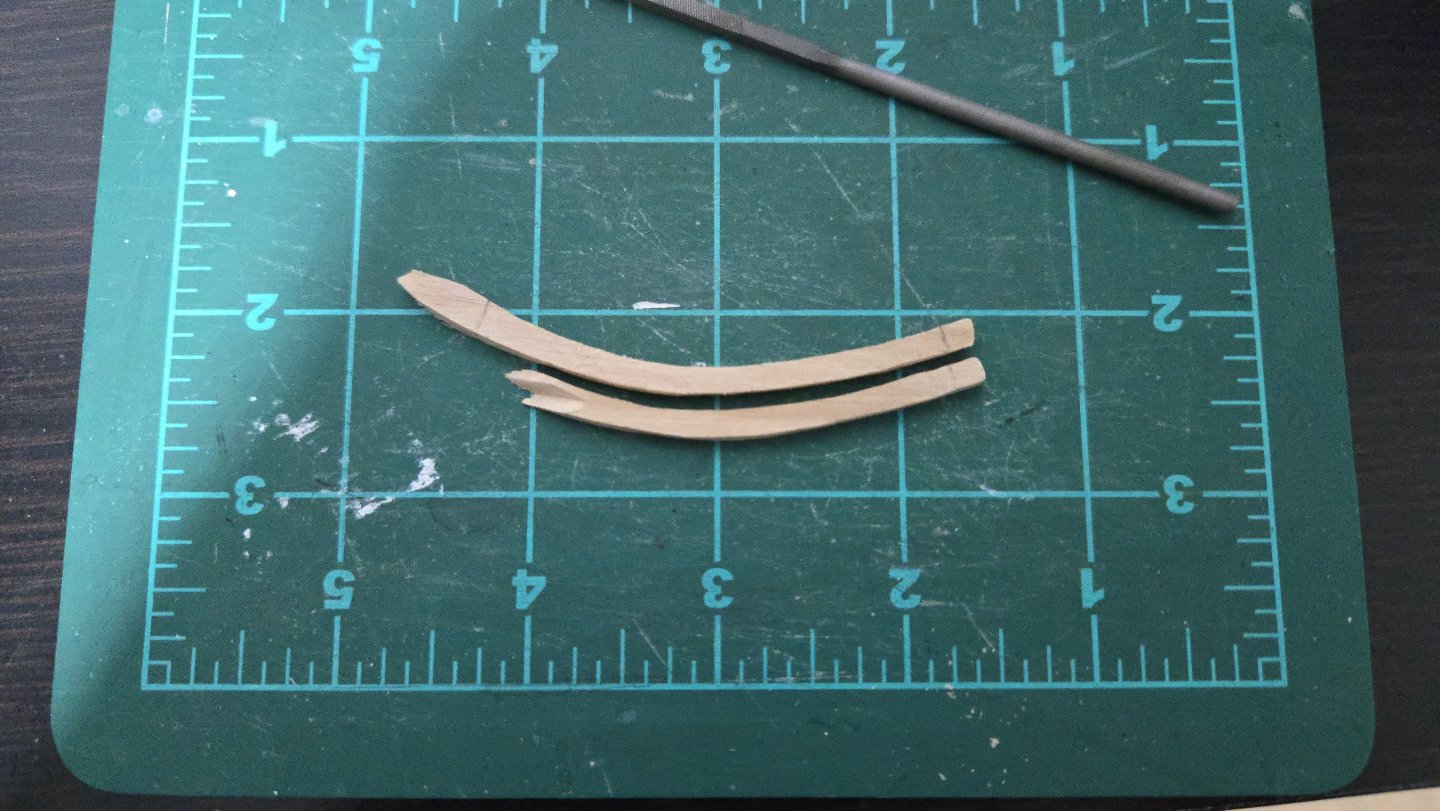
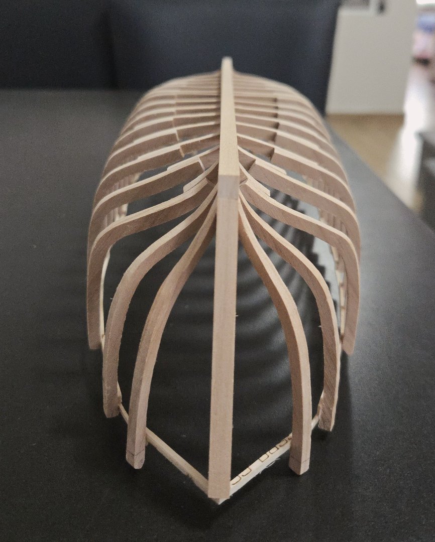
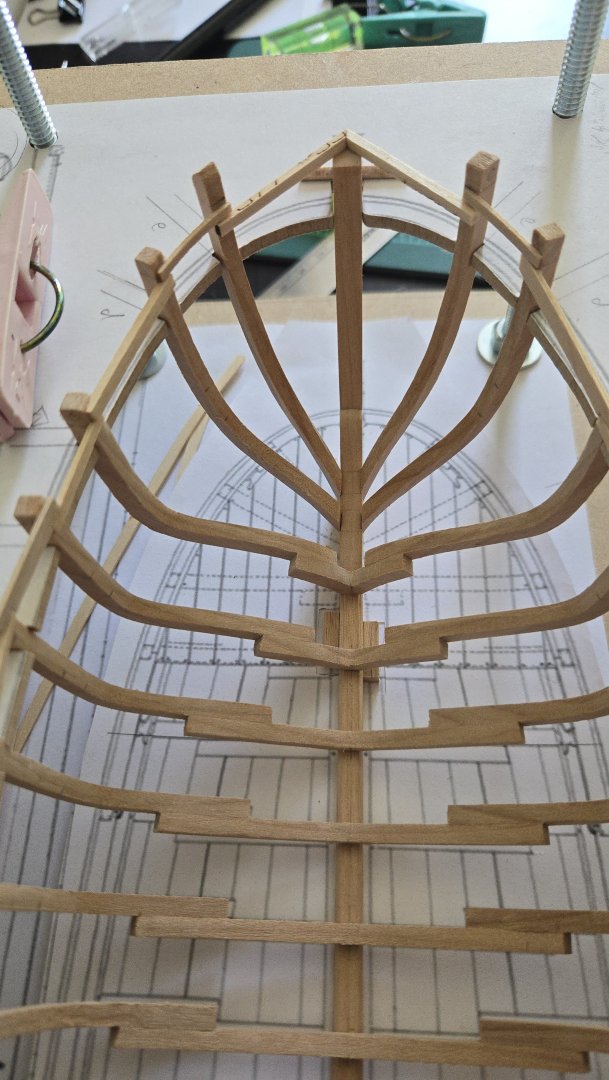
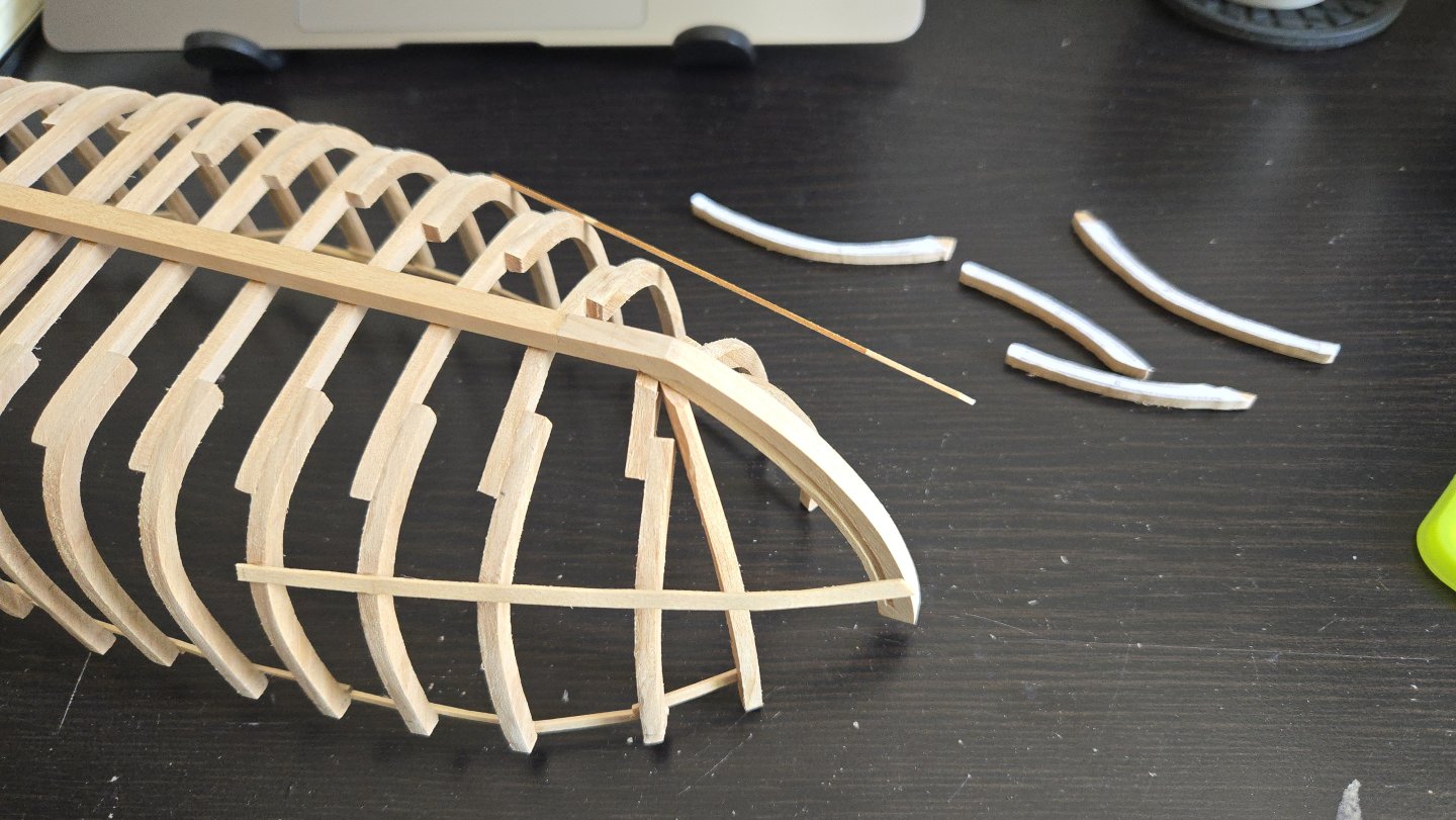
A bit more work, and I finished the cant frames at the stern. Once again, this took quite a bit of adjusting the fit bit by bit until they lined up. There's quite a curve around them to meet the sternpost, but fairing should smooth that out a bit and there don't seem to be any bulges or anything. This will be a very challenging stern to plank, though! Next up will be the bow cant frames. As I've mentioned before, the frame drawings for cant frames A and B, which run partway down the stem, don't really show their ends: So, as I'll have to do a lot of trial and error to fit these in, I decided to add a batten to help get the rough fit right. It was a lot easier to glue this in with the hull removed from the jig. They're just glued temporarily to some frames and have been left unglued at the bow, where I can use a clamp to fit them into place.


- 141 replies
-
- 14
-
-
-
- ancre
- Bateau de Lanveoc
- (and 2 more)
-
Very nice work!
-
Damaged model, looking for the original details on it
JacquesCousteau replied to Kevin Kenny's topic in Wood ship model kits
I was under the impression that was a topmast that had fallen off the mainmast, not a separate mast in itself. If it's actually a separate mast, then the model seems to have three behind the funnels and one ahead, whereas Arizona has two ahead and two behind. Arizona also looks to me to have a much larger superstructure amidships, vs the line of deckhouses on the model. Are there other photos of the model from different angles? -
Amazing work! Designing the upper level to slot into the lower one is a great way to keep everything lined up, and the precision throughout is really impressive. Out of curiosity, will there be any more planking along the side of the upper level, or is there just a narrow walkway there?