


Greg Davis
-
Posts
763 -
Joined
-
Last visited
Content Type
Profiles
Forums
Gallery
Events
Posts posted by Greg Davis
-
-
I decided to add the bow filler blocks so that I could make a nicer transition from the sides to front of the hull. In particular, I don't think I could have come close to forming the concave dip that forms on the first bulkhead. Of course this means I've taken the tack that requires this buff bow to be planked!
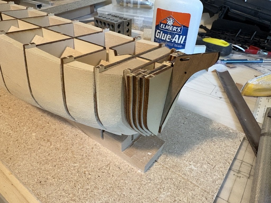
More shaping, especially on the port side, and now very close to the profile dictated by the kit's bulkheads as I'm starting to sand off laser char most everywhere. Besides the midship bulge, there is a rough transition that needs attention near the third bulkhead from the back.
-
8 hours ago, clearway said:
The 2nd plan shows exactly what i was referring to- note the ice plank supports and railing stanchions for terror on the 2nd plan compared to the upright position on the plan for Erebus (1st plan above)
Keith
Thanks Keith -
I will continue to study these plans and other material!
Greg
-
9 minutes ago, Maid of the Mist said:
Thanks Greg, this is quite depressing.... But you've given me hope.
As I've found with model shipbuilding so far, when I make mistakes it's because I couldn't see how I could have avoided them. Those planks had to be close to the bulkheads to be glued, but that meant I ended up with steps and gaps... I need a teacher, really!
I've got a long weekend this week so I'll spend some hours tomorrow evening and then Saturday/Sunday seeing if I can solve it with sanding and filler first.
I started the hobby not knowing anyone that could provide help or guidance. I read a lot of books, but still made a lot of mistakes. I still make mistakes when I'm not giving my full attention. One of the biggest differences now is that I have confidence to go back and fix what isn't to my liking. It still is depressing to have a setback, but it is not as depressing as it once was.
I think there is some truth to learning from one's mistakes and/or working thru issues that arise to find alternative ways to complete a modeling task. The Mamoli HMS Beagle kit was my first experience with wooden ship modeling. I got stuck a lot of times on that model. In fact, I shelved it a few time and started / finished a couple of other models before 'completing' Beagle. Occre's version seems much nicer and closer aligned to what the ship probably looked like in reality. I think you have made a good but sightly challenging choice for your second(?) model. Have you had a chance to read the Conway publication 'Anatomy of The Ship HMS Beagle'? While it could send you down a rabbit hole, this may be one of the best books related to the ship itself and was likely used as a reference when the Occre model was developed, thereby superseding the Mamoli model that is a poor resemblance! I now go back and forth between kits and scratch building. In many cases, I find scratch building to be easier in the sense that I don't feel compelled to make the kit provided pieces / material work.
I hope you keep at it, the learning curve can be steep at times but fellow modelers will often provide guidance and on this site are almost always positive / supportive when an issue develops. With that said, if there comes a time where you are looking for input but don't feel comfortable posting for all to see, feel free to PM if you like.
-
1 hour ago, clearway said:
Also the deck wasn't flush - there was a f'csle and poop deck and the bow sprit was at deck level like Erebus and she handled like a pig! I think i read somewhere that Captian Crozier commented after the keel was elongated after the screw was added and the bowsprit was raised she became a lot friendlier to sail!
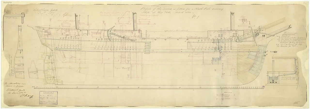
So you are (partially) referring to these draughts?
Before screw added:
After screw added / bowsprit moved:
By chance have you read:

I found the first appendix of this volume interesting, I assume similar work was done for preparing Terror at this time:


-
12 minutes ago, Maid of the Mist said:
Thank you. When you say detach the planks, presumably you just mean back two or three bulkheads? Not entire strakes? I ask because the rest of the hull is quite good. Relatively smooth and nothing like the horrible gaps and steps I have at the bow.
Yes, it would be just the forward portion. Maybe add a few bulkhead doublers to form a better base/support for gluing the new planks. This area is hard to plank with the straight planks included in the kit. Wood strips do not like to bend in as many directions as needed up front. If you replace and use the same provided material consider cutting new pieces to approximately the correct shape, soaking them in water so they become more flexible, pinning them to the hull to get the correct bends, letting the piece dry before taking off, finish shaping, and then permanently attach. This should provide a more satisfactory under-planking.
If you give this a try, and you haven't come across the topic yet, when planks are drying / your having building downtime consider checking out how planks can be 'splied' to provide a very nice fit when bent around the bow.
-
1 hour ago, Maid of the Mist said:
Any tips on application or pitfalls to avoid would be much appreciated
You may run into some problems in the region that displays a gap on the far left of the picture above. Here it looks like the strake above doesn't overlap the stake below. When you sand this out a couple of things may happen - there might be a bigger gap and/or the remaining surface, even after using filler, could be extremely thin. You may not have a good foundation for your second planking. Gaps where the two planks form a more continuous surface won't be structurally as much a problem.
Some would recommend that you detach planks in the offending regions and then re-plank. It does take courage to do that, but if the filling / sanding does not prove satisfactory, this may be a possible solution.
There may be a possibility to drill a hole between the bulkheads where the planking is problematic and then spay in a bit of an expanding foam filler; I think I saw someone do something similar (or I may be making it up!). Getting the right amount shot in would be tricky - when I've used this type of material for home repair / maintenance these products always seem to expand more than I expect! But if you get in the right amount and then start sanding, the foam could form a reinforcement to your planking from behind and help form a more solid surface for the second planking.
Either way, if you keep at it I'm sure you'll get the save
")
Greg
-
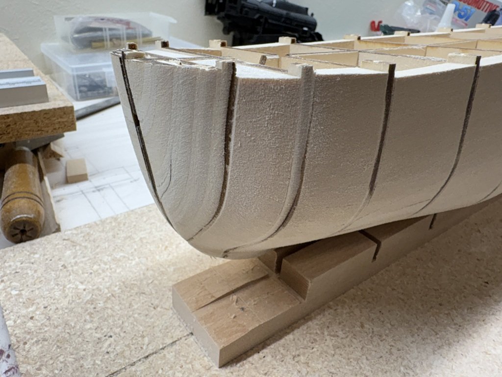
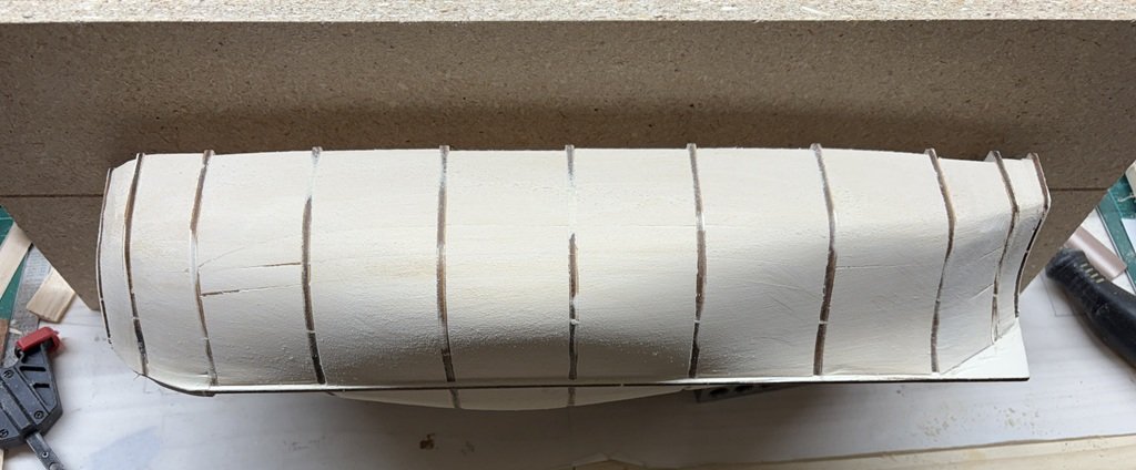
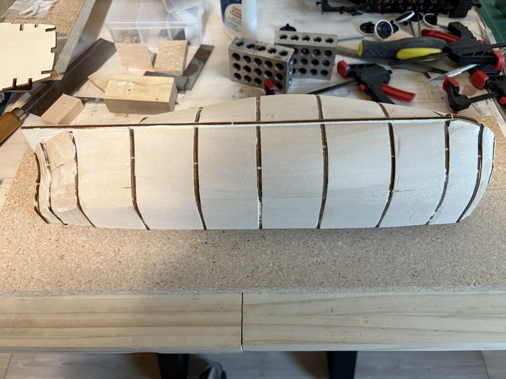
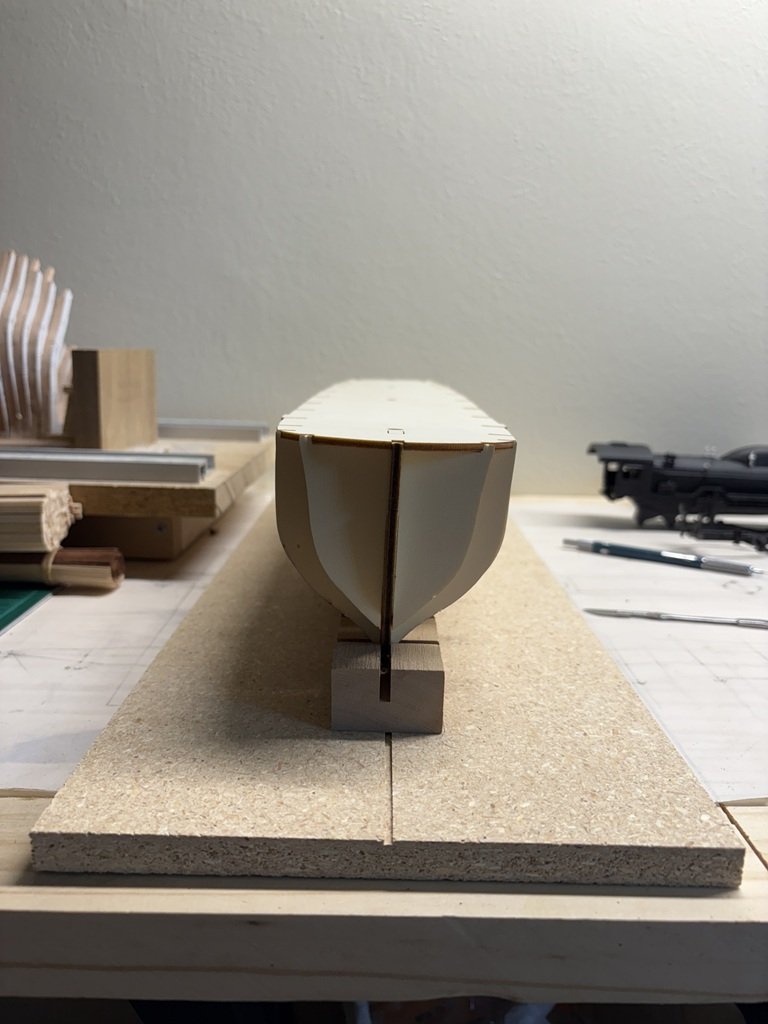
I've been spending a good deal of time each day (at least a couple of hours) shaping the filler blocks. Slow going! I'm finally getting close / starting to bevel the bulkheads. So the extreme fullness of the model has not been addressed yet. In this picture, I don't like the way the lower hull aft changes from convex to concave. Hopefully this will become a more graceful transition as the work continues.
 On 8/19/2025 at 2:57 PM, Maid of the Mist said:
I have a book about Erebus by Michael Palin, which I believe was a similar sort of ship to Terror. I think they were both originally designed to fire mortars or primitive rockets (hence their suitably scary names!)
I have the Palin book on order - it is suppose to arrive tomorrow. Right now I'm interested in learning more about Terror's time during the Ross expedition in the Antarctic. Antarctic expeditions have been always more interesting to me than those in the Artic. In fact, I am considering portraying my model closer to that time period - i.e., before the modifications such as the addition of the screw present on the Franklin expedition. From what I currently understand, this would have me installing a different shaped rudder and giving me the opportunity to copper the hull. The latter is inviting to me! Plenty of time to ponder this as the shaping process continues.
-
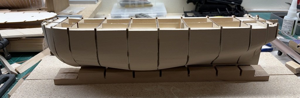
Did some more hull smoothing and now have added fillers to the remaining 3 spaces defined by the bulkheads. Quite a 'buff' bow on this one and a quick transition aft from the full mid-section. I would guess that Terror was not a fast sailing ship!
- JacquesCousteau, Jolly Jo, clearway and 1 other
-
 4
4
-
7 hours ago, Maid of the Mist said:
Is using filler blocks a common method? I haven't seen it before and it seems like a lot of extra work
Using filler blocks is not uncommon. They are very often used near the stem and stern on plank on bulkhead models - places where there is a good deal of changing curvature on the hull. When preparing the hull for planking, the filler blocks can help define the shape of the finished hull. As, or perhaps more importantly, the filler blocks then provide a larger gluing surface for the hull planks. I think you very well identified some of these issues in one of your posts (#4) about your experience building the Polaris kit.
For this model I've chosen to use filler blocks to help shape the hull envelope as well as to deal with alignment of the bulkheads / false keel. Some kits do a better job in terms of more closely spaced bulkheads and stiffer material and/or additional lengthwise wood inserts that keep the structure closer to true. (Some builders fabricate and add additional bulkheads between the bulkheads provided in a given kit.) The Terror model is quite flexy as designed so the blocks make it more rigid. It does take time to fit the blocks and then to shape them, but the tradeoff in an easier / nicer planking job can be expected. Still one needs to be careful in how the work is done - I hope you read some of the earlier posts in this build on how I made a royal mess out of the model when I wasn't paying attention to what I was doing!
The first several plank on bulkhead models I made did not have much in the way of filler blocks, but I have used them for the whole hull in the last 5 or 6 plank on bulkhead models I have made. There are times during the hull shaping / sanding process that I question myself about the time and dust involved during this step, but when I get to planking I am always happy I did the underlaying work. Additionally, I actually like the extra weight the hull / model takes on from the added wood.
By the way, quite a fine job on your first model! Perhaps you could try filling a few regions in you next model to see how the process works and determine if the method would be one that is helpful for you. I'm sure you have already noticed that collectively model ship builders often have many methods for achieving / working toward the same type of outcomes. What works for one person may or may not work for others. But if you have the time / energy to try different methods you may be able to add to your modeling skill toolbox.
Happy modeling and I do hope you start a log for your Beagle model.
Greg
-
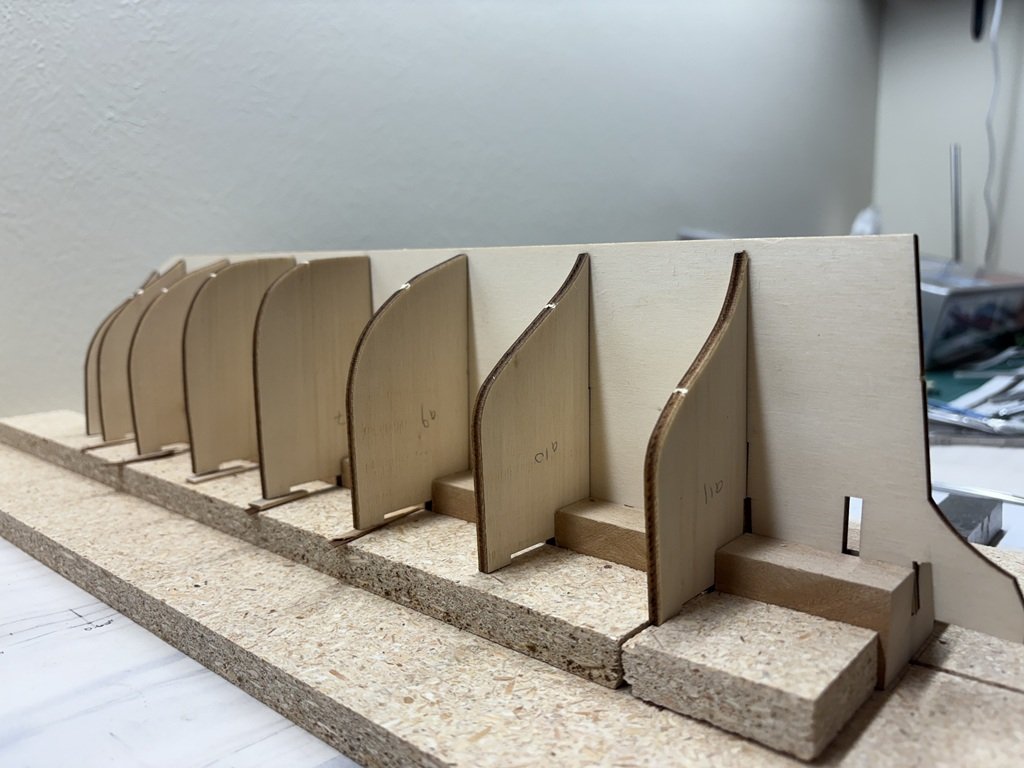
I finished attaching filler blocks in these 7 spaces and permanently attached the final 3 bulkheads using the false deck to help with alignment.

At this point I decided to detach the false deck (again) and begin the shaping process of the filler already in place. Once this is in pretty good shape I will add filler to the remaining bulkhead spaces and blend them in with this work. I started the shaping process with a Dremel tool using one of their carbide sanding disks. This work went pretty fast, but did result in a lot of dust that require sweeping and vacuuming! While not my favorite place to do this kind of work, it was done indoors since the temperatures were close to 90 today. That got me to here:

Currently the hull is sitting in the hull jig and is getting a next level of shaping / smoothing with a rasp:

I plan on smoothing close to the shape given by the kit's bulkheads and then will make refinements with the aid of the body plan in Betts' book. As pointed out by other builders of this kit, there are some extreme changes in the hull shape as you move away from midship near the turn of the bilge.
-
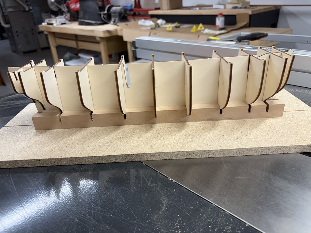
Another layer of filler blocks in place. These are thicker than the diagonal pieces - close to an inch. I did cut some excess off each piece with a bandsaw before attaching the blocks. Still a lot of wood to be removed because I did not bevel the cuts at all. Much more efficient than filling with the plywood strips - hopefully the basswood and bulkheads will have similar sanding attributes.

-
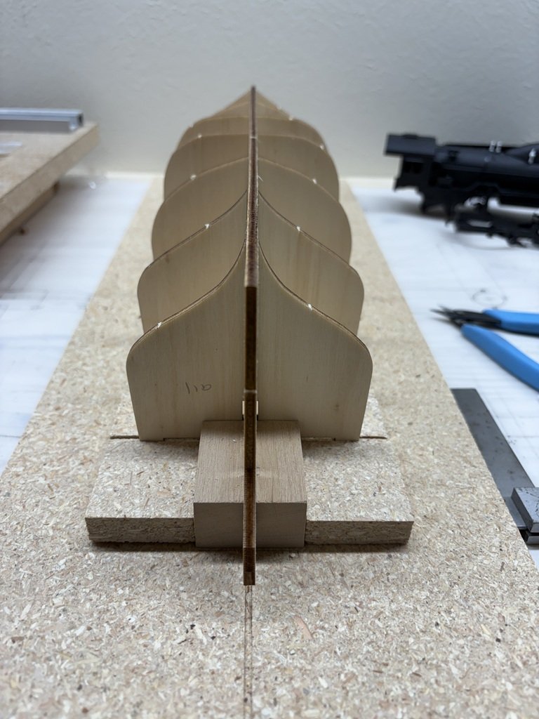
Pulled the false keel / bulkhead structure off the jig and found that the subdeck fit nicely over all the bulkhead extensions and was true!
Sitting as it is I fine it interesting how far out the middle two bulkheads extend in comparison to the ones before and after. Some work will be needed to get the hull closer to the lines that Betts presents in his book.
I plan on turning this back over now and to then fill the lower spaces defined by the seven bulkheads that are in place. Then I will add in the three missing bulkheads, secure the subdeck, etc.
I'm hoping to get the filling / sanding / under-planking / sanding / ice-bumpers / sanding down before the weather turns bad this fall. I prefer to do the big sanding task outdoors!

- catopower, Jond, JacquesCousteau and 1 other
-
4
-
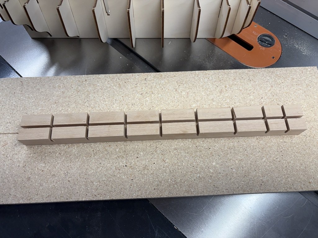
Everything was still pretty square today, but I could still sense flexibility in the bulkheads that I wanted to get some control of. I decided on matched sets of diagonal spacers / filler pieces. I couldn't find material laying around to do the job, so off to the lumber store to by less than $9.00 of basswood:

Yep over 6 feet of 8 inch wide and 7/8" thick basswood. Wood savings can be had if you have tools to cut it up! A little bit of time with table and band saws left me with 2.5" sheets of just under 1/2" material that I cut to final widths on my Byrnes saw. So between each pair of bulkheads is a piece of basswood having the same width that equals the spacing coming off the false keel:

This has really tightened up the system and will make the filling process quicker and more precise.
- JacquesCousteau, clearway, catopower and 1 other
-
4
-
Found a better way to use the keel holder. I inverted the false keel / bulkheads in the jig. I then 'packed' the space evenly between each bulkhead and the jig. Now each bulkhead from 2 to 11 is square to the false keel in all three dimensions - not just the two as before - and the twist is removed from all the bulkheads! Bulkheads 12 and 13 are not added now because I had not made slots for them when I envisioned having the hull right-side up. The false deck should be quite flat / stable along the greater part of the hull and then will be able to align the last two bulkheads.
I'll do another check on the alignment and then start attaching the bulkheads permanently. I expect that I can add a good portion of the between bulkhead filler while it is stabilized upside down in the jig.
- clearway, Jolly Jo and JacquesCousteau
-
3
-
I've more or less sorted all the parts from the kit and placed them into different containers until needed.
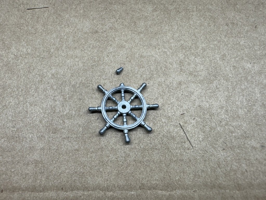
I've noticed a couple of differences between the two kits I've obtained. The new kit came with sails (the first did not) and this one has slightly different steering wheels. I like the new ones better; unfortunately one was damaged as it bounced around the box.
The fit of the bulkheads in the false keel is a bit looser than the original kit. The false keel and false deck have a small amount of warpage, but I'm attuned to the issue and will work it out.
To help me keep everything lined up / straight I've begun to build a keel holder for the model.
Here's the false deck being fitted along with the bulkheads - nothing glued to this point. I see a little twist currently that needs to be fixed, but nothing like I did in try #1.
-
5 hours ago, clearway said:
this ship is fighting you all the way Greg! - i had the plastic containers for my Occre Erebus and Endurance stashed on a shelf under the workbench and when reaching for something else under there they slid off, opened and mixed all the fittings up including all the extra 4mm and 3mm deadeyes i had ordered for Erebus on top of all the 5 mm ones from both kits 😱.
Keith
Hopefully the fight is fair and the builder prevails!
Mixed parts is a wonderful sorting opportunity - I've read this is good for your health.
-
7 hours ago, Maid of the Mist said:
The exact same thing happened to me with my OcCre Beagle. The same parts escaped too! I'm still finding the odd one on the floor.
This is the 4th Occre kit I've purchased - everytime I've experienced the broken parts box; but this one was the worse. The exterior boxing for shipment was nicely done, but it seems any pressure on the parts box results in cracks / loose parts. I know there is at least one block that jumped onto the floor; maybe I'll find it someday!
-
A new box has been received and the crew is being called back!
Very glad Occre shrink wraps their kits as the plastic box of fittings didn't hold up in transit. Looks like a good proportion of the fittings have escaped into the box via a large hole in the lower left of the plastic box. This will be a 'fun' search and recovery given the way their cardboard boxes are made.
-
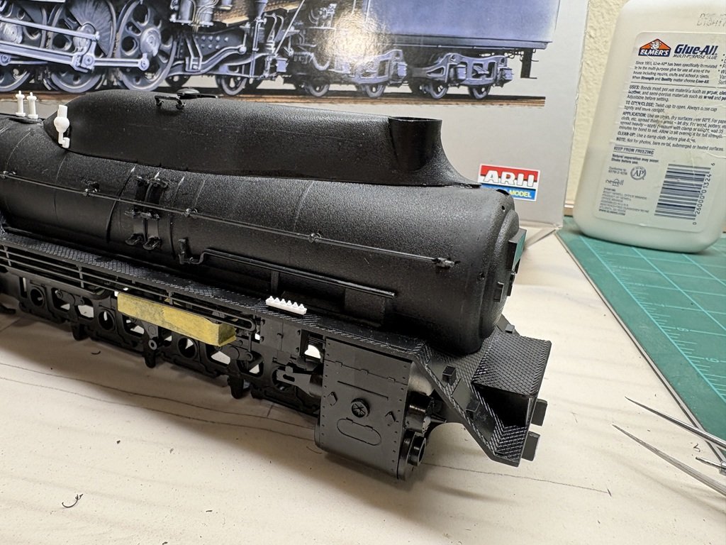
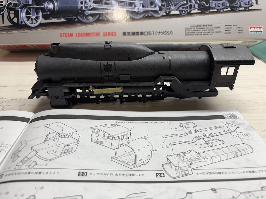
A few more additions to the boiler - rails on the front, steps up front, headlight, ... . Also cleaned up the wheels and tires and did a test fit to see the locomotive 'off the ground'.
Two things of note here. First, the instructions have the builder attaching the wheels / tires to the chassis before the cylinder assembly is added. I have already added this assembly because I wanted to paint it with the chassis as a complete unit - almost a very bad idea! Its hard to see in the above picture, but there are pieces that extend to the back of the cylinders and are part of the running gear. Turns out that with that in place, there is not enough space to slide in the first wheel / tire as one. Fortunately, if the tire is removed, the wheel just makes it into place and then the tire can follow!
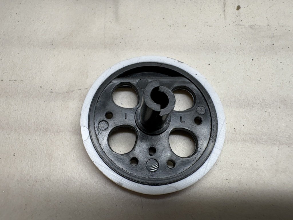
Second thing of note is an unexpected aid in how the wheels have been molded. There are three types of wheels for each side; the instructions label them as 1L (2), 2L, and 3L (similar for the right). While you can tell the difference by carefully looking at the counterweights, the model creator's molded the designations into the back of each wheel - a very nice touch.
Generally, I like the look of the drivers on all locomotives, but even more so the spokeless drivers like those on this machine. It continues to amaze me how precise the wheels and tires needed to be machined so that the tires could be heated and slipped onto the wheels prior to cooling.
- yvesvidal, Old Collingwood, Canute and 3 others
-
6
-
Today I learned that the rail gauge for this locomotive (common in Japan) is Cape Gauge 3' 6". Wider than U.S. narrow gauge of 3', but not as wide as our standard gauge of 4' 8.5". I did a little 'research' since the included display track just didn't look much like O - gauge track as I was expecting since the model is 1/50th scale and thus close to the 1/48th scale.
- Canute, Old Collingwood, Jack12477 and 1 other
-
4
-
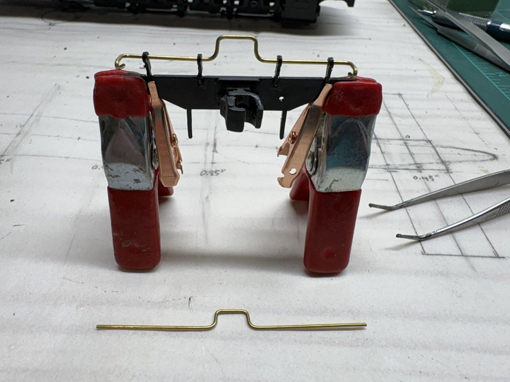
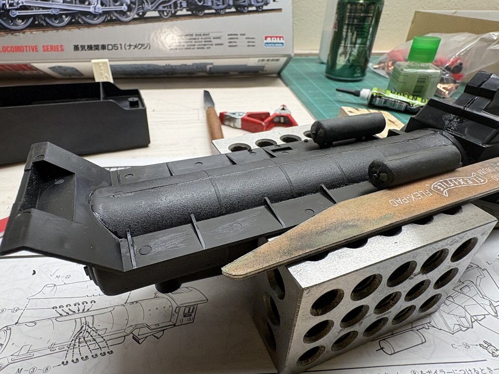
I fixed / added to the boiler rail by modifying an un-needed kit part. It seems that the base kit is for a later D-51 and the D-51 Slug makes use of common parts plus those needed to change the boiler appearance. So I was able to take a boiler linkage that had the same diameter as the rail and do some cutting and filing to get something that worked.
I also did some further work on the front of the boiler unit; the strangest being a railing (?) above the front coupler - for some reason, this is made from a piece of brass wire unlike all the other railing. There is an identical part for the tender that needs to be made. They came partially shaped. Getting the four plastic stations lined up is proving to be dicey process. I actually would have appreciated the unit (wire and stations) to have been molded as a single piece (which would be consistent with the rest of the kit).
- GrandpaPhil, Canute, ccoyle and 4 others
-
7
-
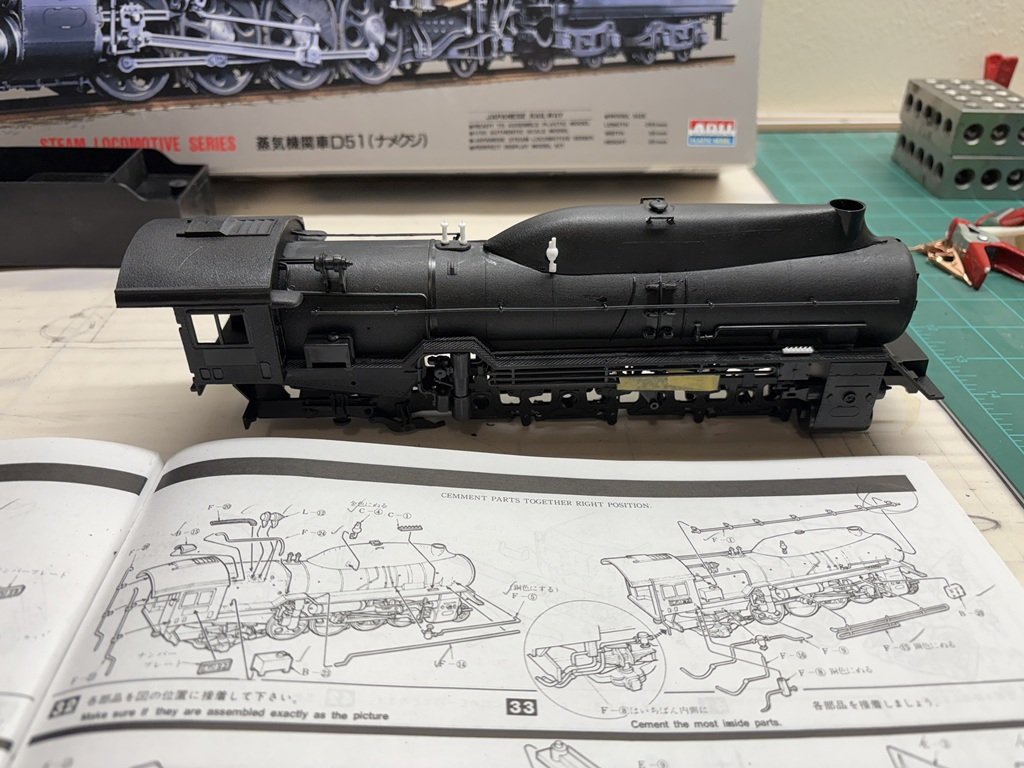
Most of the fireman's side details were added today. This is work from steps 32 and 33 in the instruction booklet. There are a number of parts that fit below the cab on this side - mostly associated with future connections to the tender - that have not been added currently. These three pieces wrap around / under the chassis and will be added once the boiler and chassis have been attached to one another. As with the engineer's side, several parts needed work to fit as needed. The biggest issue on this side is the long boiler rail; it was not complete at the fore end - the last station and bit of rail will need to be (re)modeled and added. Fortunately the problem is at an end and even better that it will be mostly hidden behind a fairing!
- GrandpaPhil, Canute, amateur and 6 others
-
9
-
The last couple of days I've been adding the exterior detail parts to the boiler. I am mostly done with one side of the boiler now, but it has been a challenge with several pieces not fitting as expected. Here's where the engineer's side currently looks like:
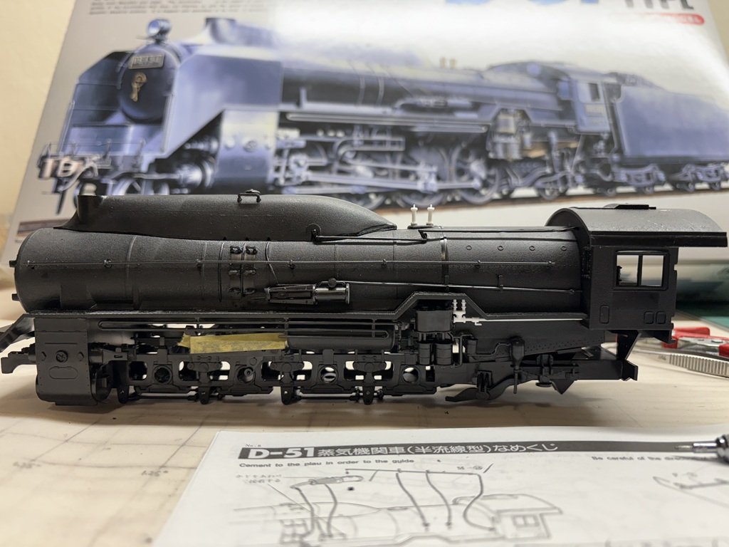
A couple of the issue I have run into (there are more) include, from left to right, no front hole for the walkway rail - easily corrected; tubing missing 90 degree bend / extension to meet front end of under walkway tank - still to be fixed; gap / misalignment of connection - has been fixed. The connection fix involved shortening the downward section and then lengthening the horizontal section. Several other parts also needed to be modified a bit to achieve a reasonable fit.
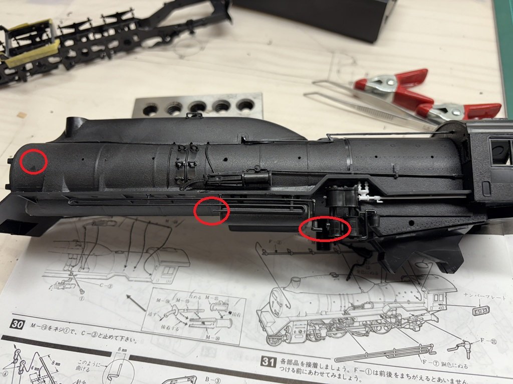
This side of the boiler won't change much prior to priming and painting.
- yvesvidal, GrandpaPhil, Knocklouder and 5 others
-
8
-
Yesterday and today I added rungs mid-boiler. This is a place that a more dedicated modeler could make quite and improvement as these pieces seem to be a bit 'heavy' and protrude outward more than expected. I did some checking online and there does not seem to be any photo-etch upgrade packages made for the Arii locomotive kits; so any upgrades would need to be of the scratch nature.
The boiler walkways were actually added before the rungs. This is one piece and it had a pretty good warp to it. Fortunately the plastic is flexible and there is a boiler length ridge / protrusion that this piece attaches to. So I started gluing by the cab and inch by inch one side to the other I made my way to the front.
In the above picture, you can see a tank under the walk. There is one on each side and each had depressions that needed to be filled and smoothed - I used Green Putty for the job. The tanks have two very small diameter / short locator pins. They do not keep the piece in place very well, so I needed to keep the tanks propped in position as the cement took hold.
Actually, before all this took place I did some work on the cab and joined the assembly to the boiler:
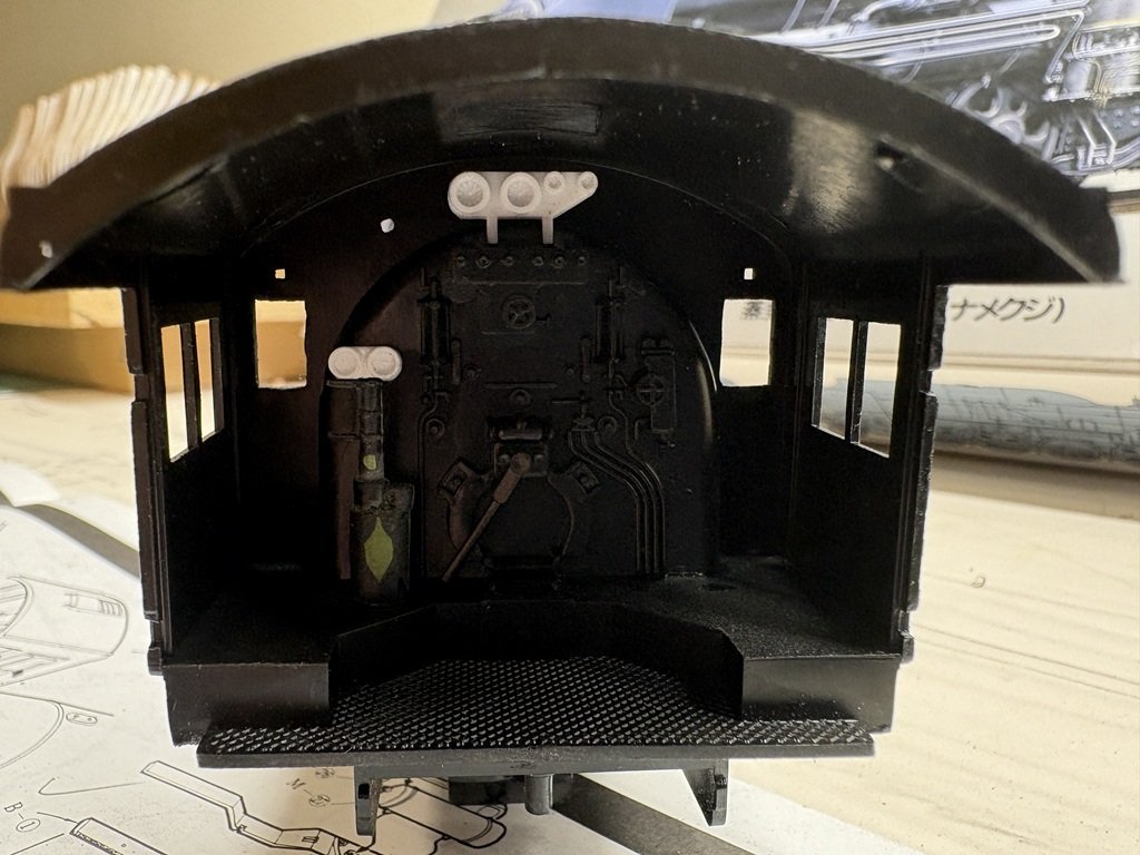
A little more Green Putty!
So that's it for now.
- Old Collingwood, Canute, yvesvidal and 6 others
-
9

HMS Terror by Greg Davis - OcCre - 1:75 scale
in - Kit build logs for subjects built from 1801 - 1850
Posted
Yep that’s an issue, looks like Occre cut in too fast! Am I right that the whole hull seems short compared to Betts’ model?