


Greg Davis
-
Posts
339 -
Joined
-
Last visited
Content Type
Profiles
Forums
Gallery
Events
Posts posted by Greg Davis
-
-
That explains a lot! I'm going to need to rely on glued joints and the rigging lines to keep everything in place. It shouldn't be a problem since these dowels are between 1.5mm and 2mm in diameter and bend very easily.
On the other hand, it is interesting that Model Expo / Model Airways is advertising the fact that the kit is made of bamboo and Freijo wood because the original plane was built from these materials. I am so used to the arguments in model ship construction to rarely (or never) use the same wood the original ship was made from because of one would like the grain of the wood to shrink with the scale of the model. I wonder if there would be a another material to build a 1:16 model of the 14bis with that would respect scaling of grain and have better ability to hold bend shapes.
Now I need to put these ideas out of my mind before I go down a rabbit hole, researching everything I can about the plane and start over with a completely scratch-built model ... Keep to the kit, keep to the kit ...
-
Mark -
I tried that initially - as directed in the instructions, I soaked the ribs (in the jig) with water from wet paper towels for an hour and then used a hair dryer on high to dry them out. I then left them in the jig overnight expecting the ribs to hold their shape. They had some curve, but not as much as desired. That's when I went to soaking the ribs in water, pinning them to the plans and letting the wood dry on its own. But there was essentually no improvement in holding the shape. Bamboo is new to me in this type of application and it surely doesn't behave like wood I've used / bent for making model ships!
It might be the case that if the jig had been designed with a more extreme curvature, then after springing back the ribs would be close to the needed shape. I imagine that a good deal of experimention would be needed to get this type of a jig right.
I'm just hoping that the bamboo is flexible enough so that the shape is held by the way the components fit together together with the rigging that comes later. At this point I think that will be the case, but time will tell.
Greg
- Jack12477, king derelict, Egilman and 5 others
-
 8
8
-
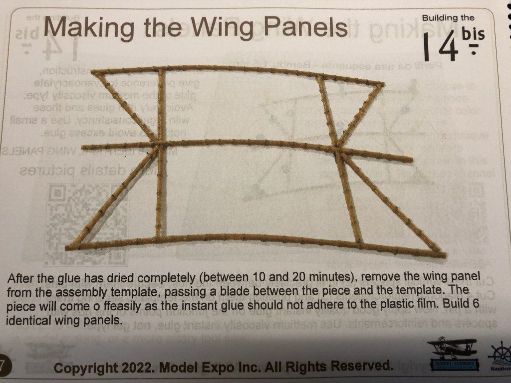
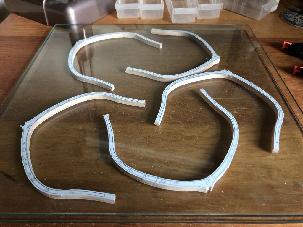
This afternoon I checked to see if the resoaked strips were holding the desired shape - not any better than when they came out of the rib jig. The amount of curvature doesn't seem to be something the bamboo dowel wants to hold. I decided not to be too concerned because the material is so flexible and went ahead to insert the spacers and diagonals. I fitted the eight pieces and put a bit of CA on each joint region, let it dry, turned the structure over and put another drop of CA on the reverse side of each joint. The end of each rib was trimmed to finish this stage of the assembly process.
Here is the resulting first wing panel:
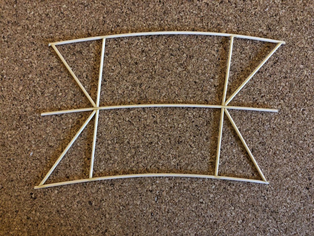
For reference, the panel just fits inside a trapazoid with height 3.75" and length 6.26".
The diagonals and vertical spacers are holding the desired rib camber for the top and bottom ribs, as well as for the mid-portion of the middle rib. the ends of the middle rib spring up just a bit now; however, later in the build there will be vertical rigging that attaches to the ends of the ribs. By rigging from bottom to top the middle rib ends should be able to be pulled down into their correct position.
Five more panels to assemble!
- Egilman, GrandpaPhil, thibaultron and 7 others
-
10
-
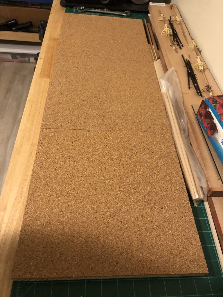
I bought a 1 ft x 3 ft sheet of pine - it is the kind made up of strips glued together. I find that these stay pretty flat and don't cup or warp much. I then attached 1 ft squares of cork to the wood using heavy duty double sided tape. This will become the basic building board for the wing panels / fuselage sides, etc.
Here is the start of a pair of wing panels, the soaked (for the second time!) ribs are held in place with push pins:
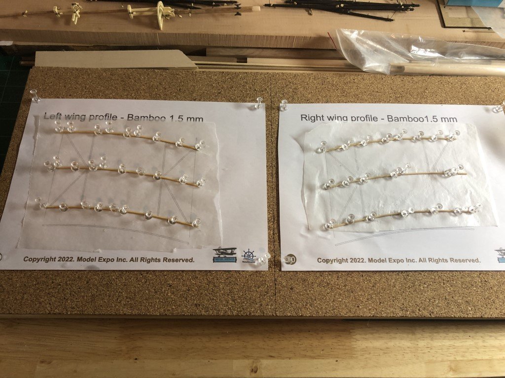
I'll let the ribs dry overnight once again and start glueing up the remaining components tomorrow.
-
I left the ribs in the jig for nearly 24 hours; took a couple out and as expected, they are not keeping their shape very well. Six are soaking in warm water now and then I will pin them to the building board in the right shape. I will let them dry a bit before adding the rest of the wing panel parts.
Did a little research on bamboo last night, trying to find out more on the distance between nodes. It seems that there is a good deal of variability based on the diameter of the bamboo and the species (of which there are apparentaly hundreds). I alo measured the distances between nodes on a piece of 3/4" diameter bamboo that I have. These distances averaged a bit more than 10 inches. The material in the kit is 1.5mm. If this is correctly scaled, the actual plane would have used 2.4 cm; i.e., about 1 in diameter bamboo. I would think that it would be fair to guess that the nodes on this diameter bamboo would be roughly 1 foot. Since the model has ribs with length 6 1/8 in, this would implie actual length just over 8 ft. In turn, I would think maybe 6 nodes, since you would likely minimize the number of nodes / not have one too close to the end of a rib.
Interestingly, the count of nodes on the ribs shown in the instruction booklet is in the 20 - 22 range - this number of nodes would be equivalent to a node spacing of around 4.5". I think this may be too small of a distance and that 6 or 7 nodes would be more realistic. So I will likely go with that number.
Here is how I think I will proceed on each panel:
- resoak / shape ribs after they have been in jig
- glue in the vertical spaces and diagonal reinforcements (before painting / adding nodes)
- trim ribs to appropriate length
- add nodes individually (not using blanket stitch as in video)
- paint with yellow ochre acylic
It might take a little longer, but the result may be a bit better. I don't like their idea of painting and then gluing.
- Egilman, Old Collingwood, Canute and 5 others
-
8
-
14 minutes ago, Egilman said:
It was very difficult to turn, she liked to drop the inside wing when attempting to turn.... The reason was loss of airspeed on the inner wing causing a corresponding loss of lift...
The design was at fault... Dumont had used Otto Lilienthal's table of pressures to create his rib curves and did not believe the Wright's published table of pressures... It was this that caused him to add so much dihedral to get it stable, but it still didn't solve the wing stall problems in turns... He made the forward fuselage so long to increase the combined box elevator and rudder's leverage and it was his best idea on directional control...
At best, it lumbered through the air like a scow with a drunk helmsman... But it could get into the air....
What amazes me is the almost total lack of insight in most of the aeronautical community in those days, almost the entire world's best and brightest scientists and engineers couldn't see the way to go...
It took two inspired bicycle mechanics from Dayton Ohio... The Wrights didn't get any respect from the rest of the world, their discoveries were ignored, until the lauded and storied university degreed world was shown the light of day....
This is going to be a beautiful, Stunning, model...
Thank you for the added info!
Dumont's plane, in some ways, reminds me of some of the early MPA (man powered aircraft) designs. My dad had been a B-17 pilot in WWII and afterwards became interested in experimental aircraft and very much interested in MPA's. By occupation he was a design engineer and this helped him design a (potentially) functional MPA. I remember all the work he did on it when I was young - for example, the ribs were made out of 1/8" square pine stringers; the wingspan was to be about 40 feet - but the project was never completed. I guess it eventually took too long and he lost interest. When I was a teen and building a lot of free flight and control line planes, I did try to work on his plane as well, but it really didn't help that much. It should have though as I ended up a reasonable bicycle racer that could easily wrench my bikes as well as a mathematics professor.
- mtaylor, Jack12477, GrandpaPhil and 4 others
-
7
-
Ribs have been soaked via the suggested papertowel method. I also blew hot air on the wetted ribs for a while. Still not overly confident that the hairdryer will have done its thing, so I am going to leave the ribs in the jig overnight before attempting the wing panel construction.
Before starting the wing panels a very important decision needs to be made - use the smooth bamboo dowels as provided, or try to simulate the periodic nodes that make bamboo truely recognizable. As mentioned before there is a video on the @Nauticurso YouTube channel: https://youtu.be/vR30vUZwG8A . The suggestion is to paint the trips with yellow ocher (can do that!). Then to simulate the nodes thin rigging line is wraped around the dowel using a blanket stitch. Finally they cover the whole dowel / rigging line structure with CA to fix the line in place.
The whole process looks pretty messy (and full of CA vapor); but also seems to leave a thread between each of the circular nodes. I would like to have the nodes represented, but I don't want the line between them. I'm trying to think of a way that these lines are removed from the finished work - perhaps they can be cut and carved off the dowel after being afixed. I guess the best thing to do is an experiment or two!
- mtaylor, James G, king derelict and 6 others
-
9
-
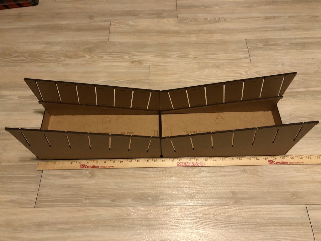
I also have assembled the wing building jigs. They are substantial structures.
When set side to side you can get a good idea of both the model's wingspan (29.5 in) and the massive amount of dihedral. With this amount of dihedral the plane must have been very stable, and most likely was a factor in way it was difficult to turn. Quite different from the more maneuverable Wright Flyer design with a flat center wing section, and the wing tips acuatully dipping down at the ends.
-
I just loaded up the rib shaping jig. Within the bunch of provided 1.5mm diameter bamboo strips there were plenty that slid into the jig. The bamboo being very flexible takes the needed curve of camber well. The holes in the jig must not leave much extra space as I did try a couple of strips that did not pass thru the holes - they can be used for other parts of the construction.
I think it is important to note that the finished ribs are a little longer than the jig itself, so it is important that the strips extend far enough past each of the end of the jig to allow for trimming later.
Now it is time to soak the ribs and to see if the wood will take the curve permanently (or at least long enough to get them glued up in the wing panels). I'm not sure about drying the ribs with a hairdryer vs leaving them in the jig long enough to dry on their own. Some decision will need to be made in about an hour!
-
I've assembled the jig for bending the ribs. It is made out of siz pieces that are laser cut from a sheet of MDF. All of the pieces released from the sheet with ease.
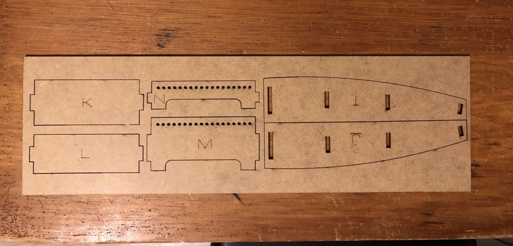
The completed jig looks like this:
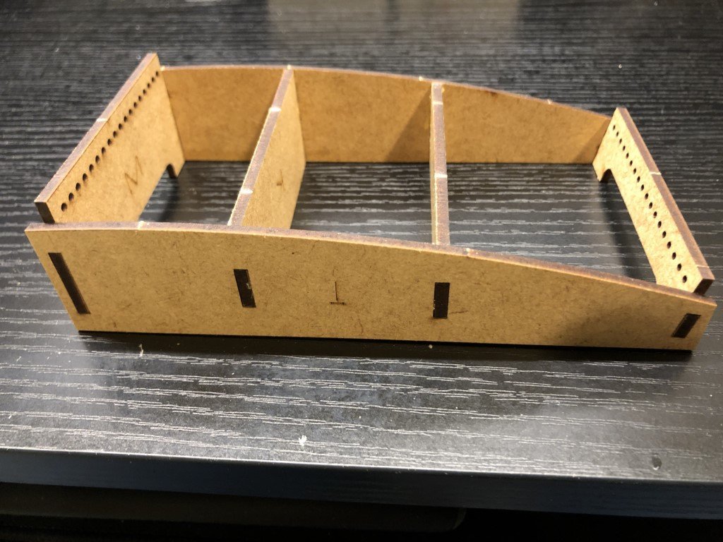
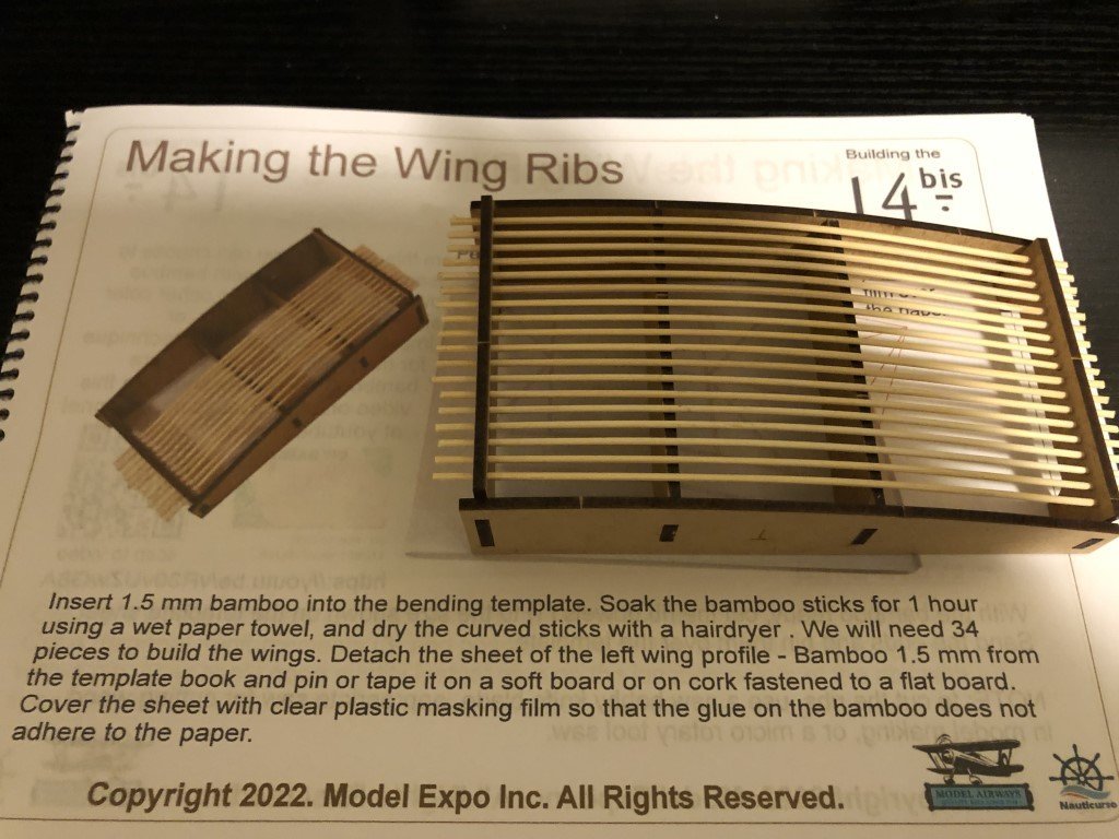
Bamboo strips will be threaded thru the holes on the two ends allowing them to be bent to the proper camber. The instructions say to place wet paper towels over the strips for about an hour. Then the builder is directed to dry the pieces with a hairdryer. The ribs can then be removed and will hopefully maintain the desired camber. Apparently 34 of these need to be made, so the jig needs to be fully loaded twice. I hope to load the jig up tomorrow to make the first batch.
Also, to give you an indication of the size of the model, the cord of the wing is just over 6 inches - the original plane would have had wings approximately 8 feet wide.
- thibaultron, hof00, Egilman and 7 others
-
10
-
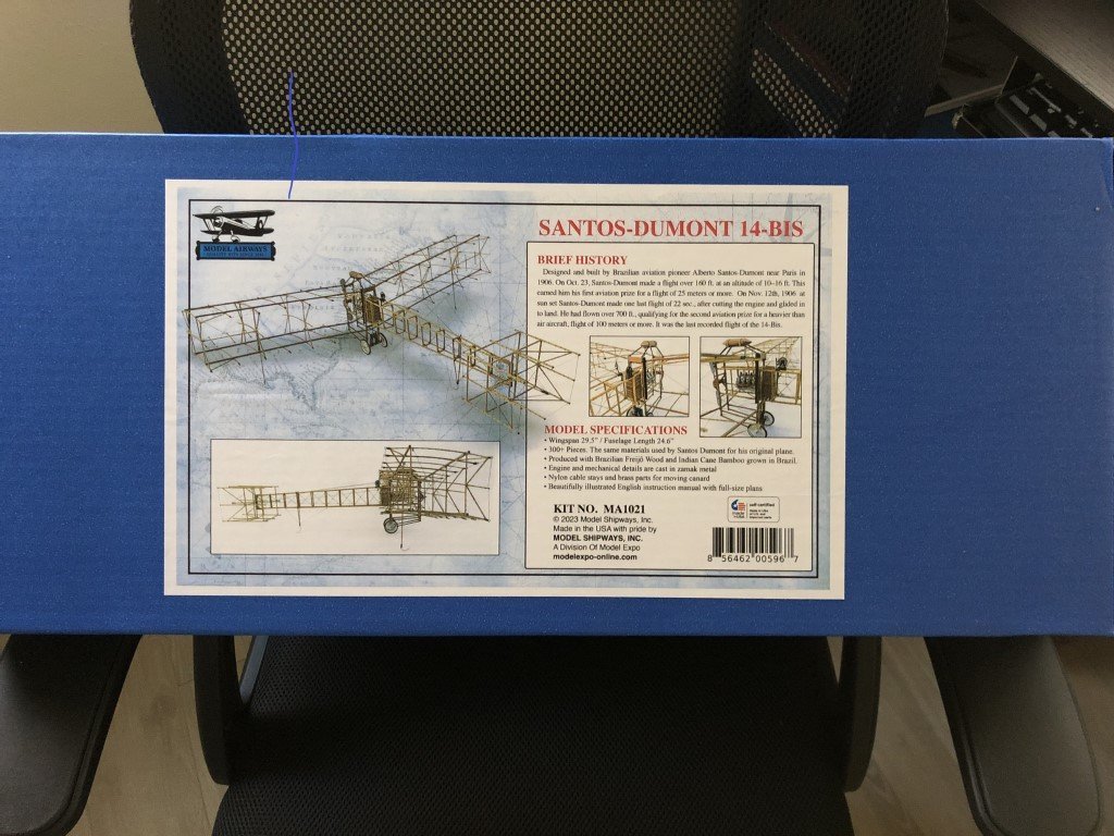
Earlier this year I had sworn off ModelExpo; however, last week I opened their site and noticed that they had released a new Model Airways kit - Santos Dumont 14 bis (1906). This plane is of great historic importance, being the first powered plane to fly in front of an audience. Built and flown by Brazilian Santos Dumant and flown in a suburb of Paris, the plane was able to win aviation prizes for first plane to have a flight of 25 meters and then of 100 meters or more. I understand that many individuals, including most of Brazil, believed that this plane was the first heavier-than-air-aircraft to be piloted (as opposed to the Wright Brothers).
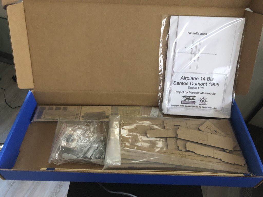
I placed an order for the kit 3 days ago and it made it to my doorstep today.
Opening the box, the contents are nicely packaged, but a bit sparse compared to a ship kit!
There is one big / full-size plan:
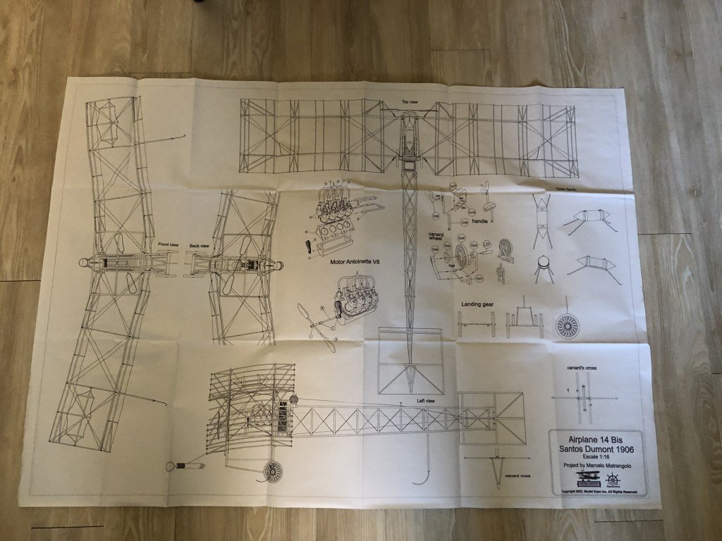
Compared to later designs, this plane always looks like it is going backwards to me. The wings / engine / cockpit are in the back. An eight cyclider engine provides power to a 'pusher' propellor.
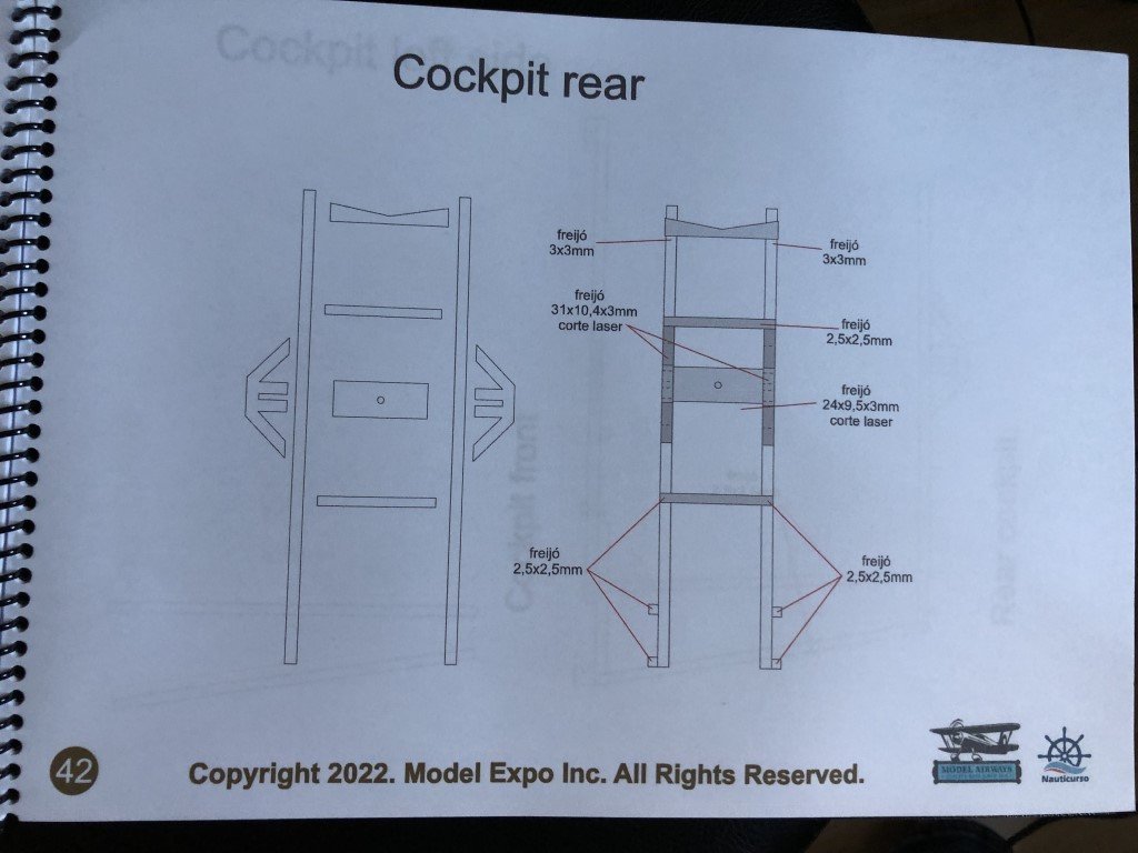
The instruction manual looks to be well done.
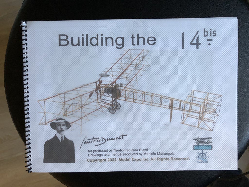
Interestingly, it is here that you find out that the kit is actually produced by Nauticurso.
Here is a typical instruction page (of which there are about 35):
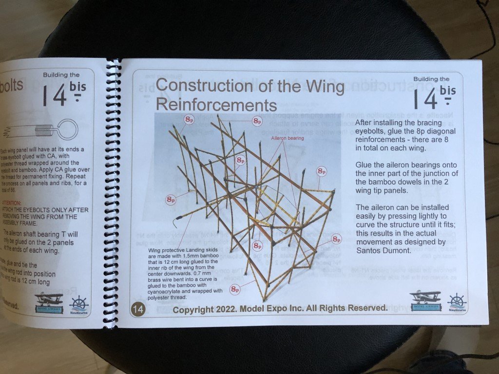
There are then a dozen additional pages of full-size plans in the manual:
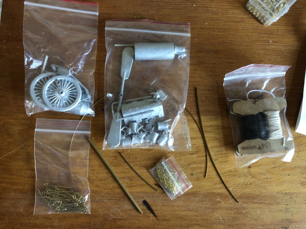
Back to the material content of the kit. There are several bags containing metal castings, fasteners, rigging line, etc. An inital look at the castings is mostly positive, but more will be known when it comes time to see how they fit together. It is disappointing that the wheels and tires have been cast together - one would expect that the tires would have been rubber. The propellor casting concerned me a bit until I read (elsewhere) that the actual blades were aluminum; I had wrongly guessed / assumed that they would be wood.
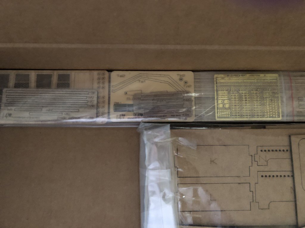
There are a few sheets of laser cut pieces and a small sheet of photo-etched brass parts:
But the bulk of the wood products are assembly jigs:
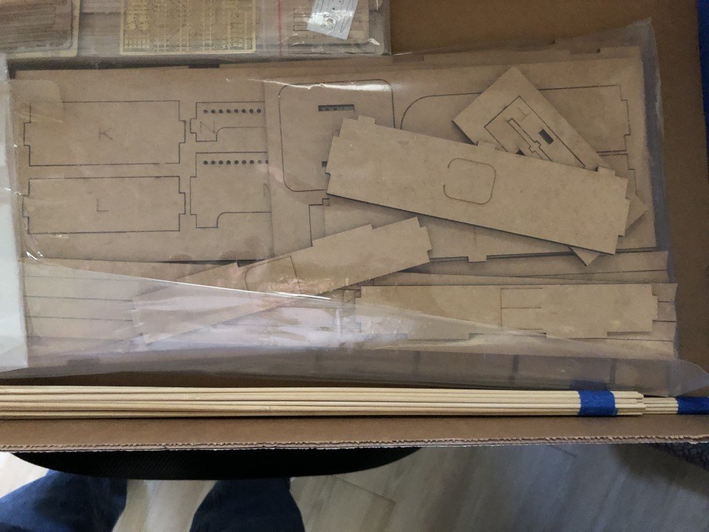
At the bottom of the previous picture are a bunch of bamboo dowls that make up most of the plane's structure. Within the instruction booklet is a link to Nauticurso's YouTube channel that shows how one can use rigging line to simulate the ridges seen in real bamboo. This had been done for the (prototype?) model in the instruction booklet, e.g.:
All in all, while there are obvious limitations, the kit looks like it will be a nice diversion and should deliver an interesting final product.
-
I thought that I would post a note indicating that I have not abandoned this project!
Through the summer, I had been involved in a great deal of work on our house - it turns out that a lot of projects needed to be done after living here for 20+ years that you don't notice as much when you are working. As the weather gets cooler, there are fewer big outdoor projects to tackle and the number of indoor projects has been shrinking dramatically.
I will also note that I am about to start yet another modeling project - a quick diversion - the new Model Airways kit of Santos Dumant 14 bis.
But most importantly, I will be back to work on L'Invention very soon.
-
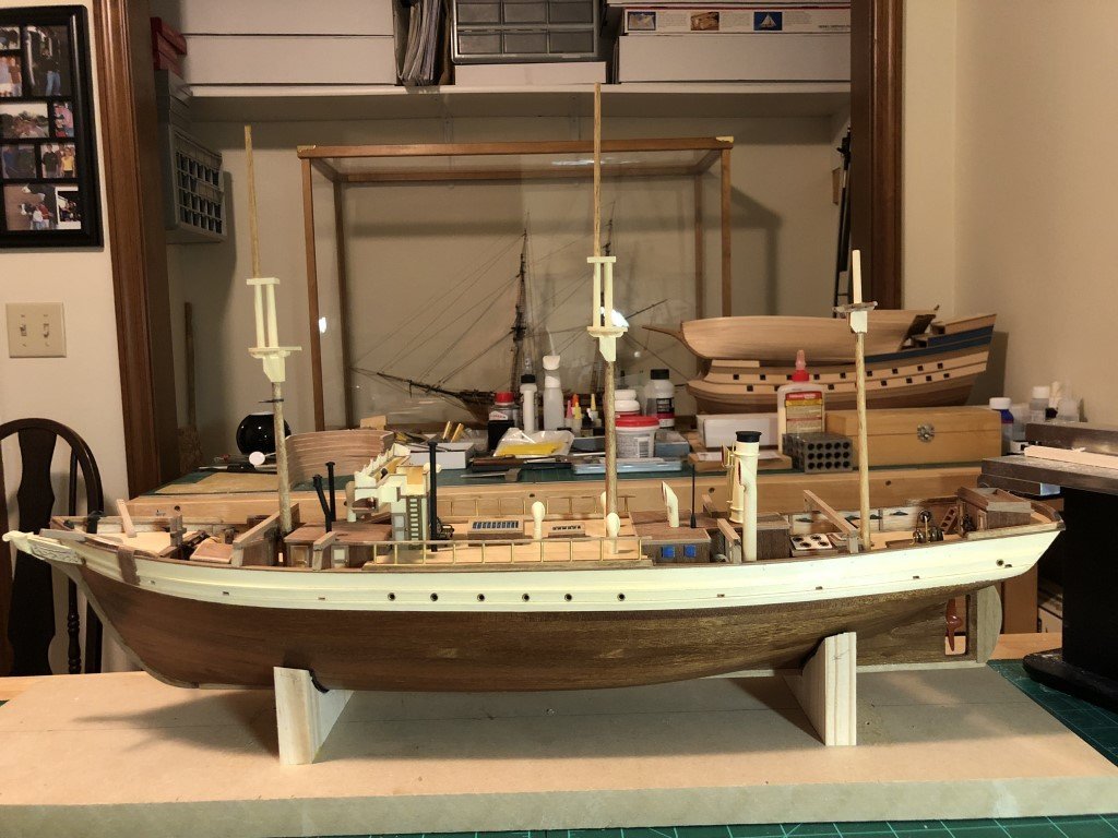
I've temporarily pinned the spars to the masts. They are not staying right where they belong, but it is giving me an idea of how much space this model will take up. Not too wide, so when cased it should easily fit in the office it is destined for.
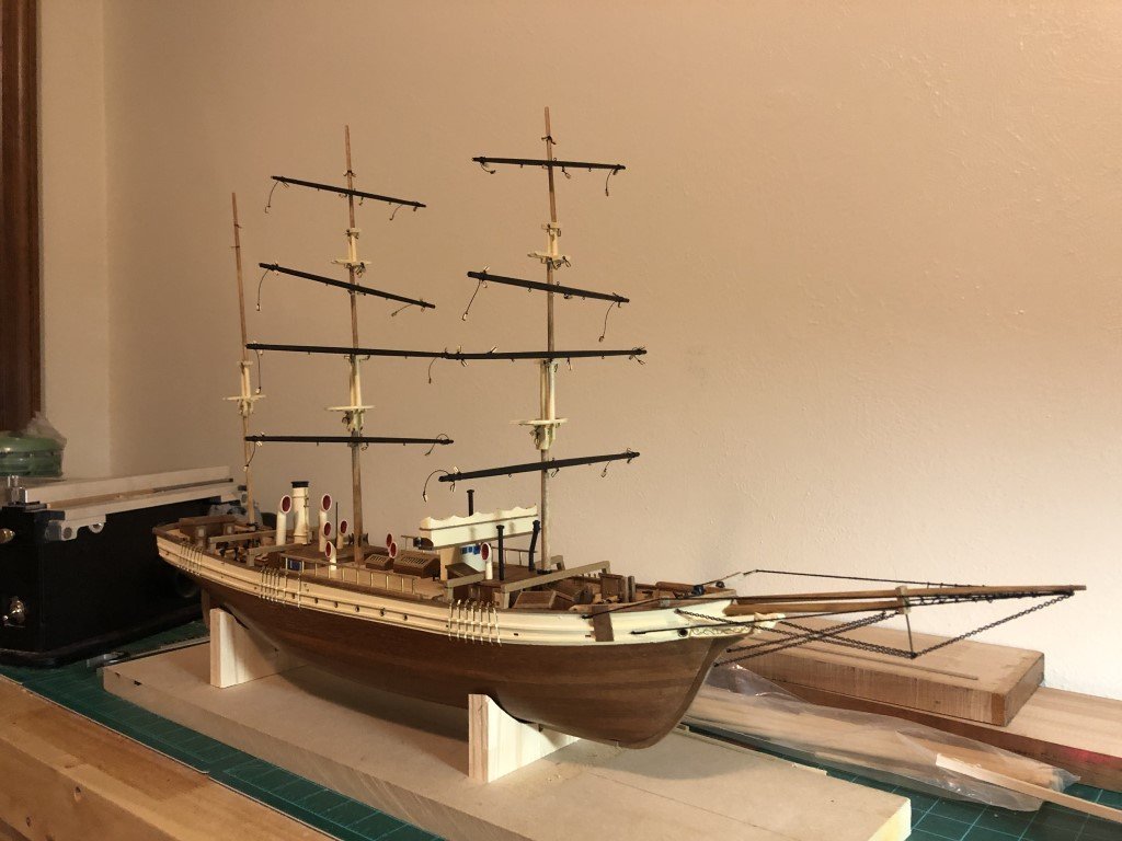
I guess it is time to get the lower deadeyes in place so that the rigging process can really get underway.
-
-
Got a little behind when I broke a couple of soft metal cleats. It turns out that getting replacement cleats of the same size proved to be a bit of a challenge. Fortunately, I found what I needed for a far price and quick overseas delivery from Cornwall Model Boats!
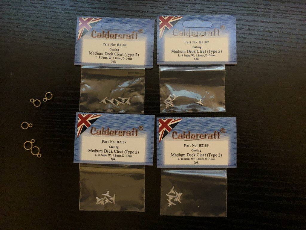
So the cleats are on, as are all of the mast blocks:
What are the chances I will cut all of the waste material and not any of the block attachements on the main and mizzen masts?
-
I believe that all of the standing rigging is done up front!
- clearway, Keith Black, consitution and 1 other
-
4
-
Rubbish weather is the best! Everything is looking soo nice on your model!
- clearway, AJohnson and Keith Black
-
3
-
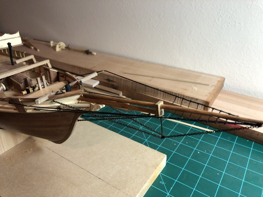
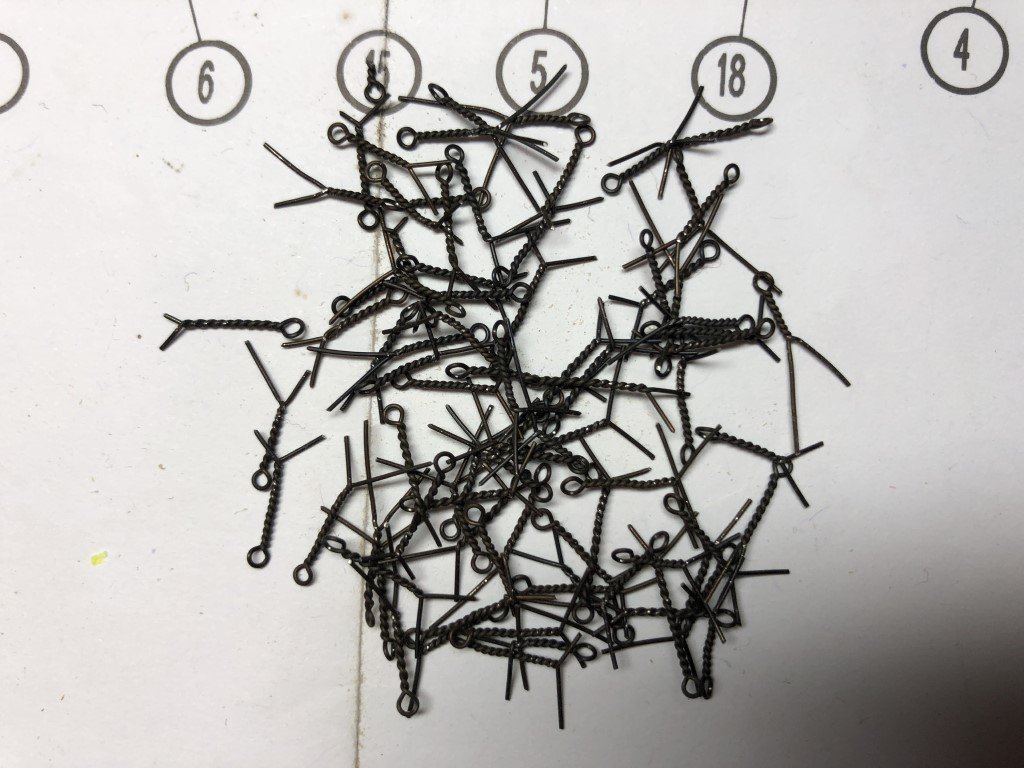
All of the chain-plates are attached. I spent some time making around 150 eyebolts out of 28 gauge black annealed wire to replace the supplied eybolts. All the eyebolts on the deck / hull have been attached.
I've also assembled and attached the bowsprit - now the ship is a bit longer!
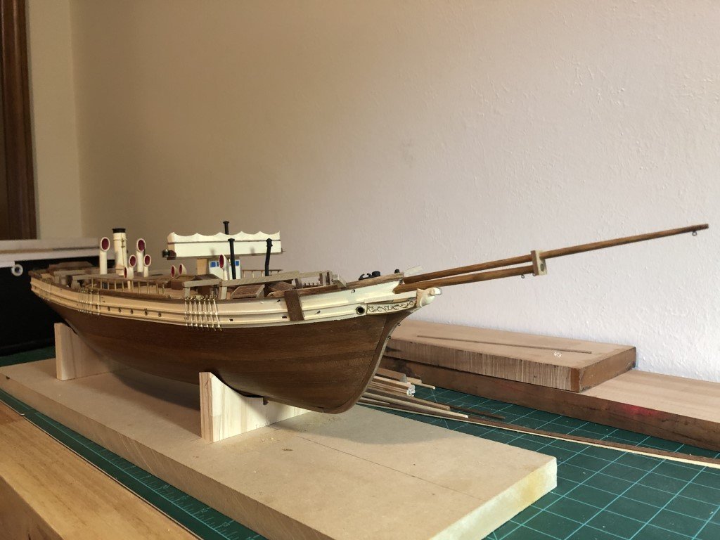
I think the dolphin striker / martingale will come next along with rigging of the bowsprit.
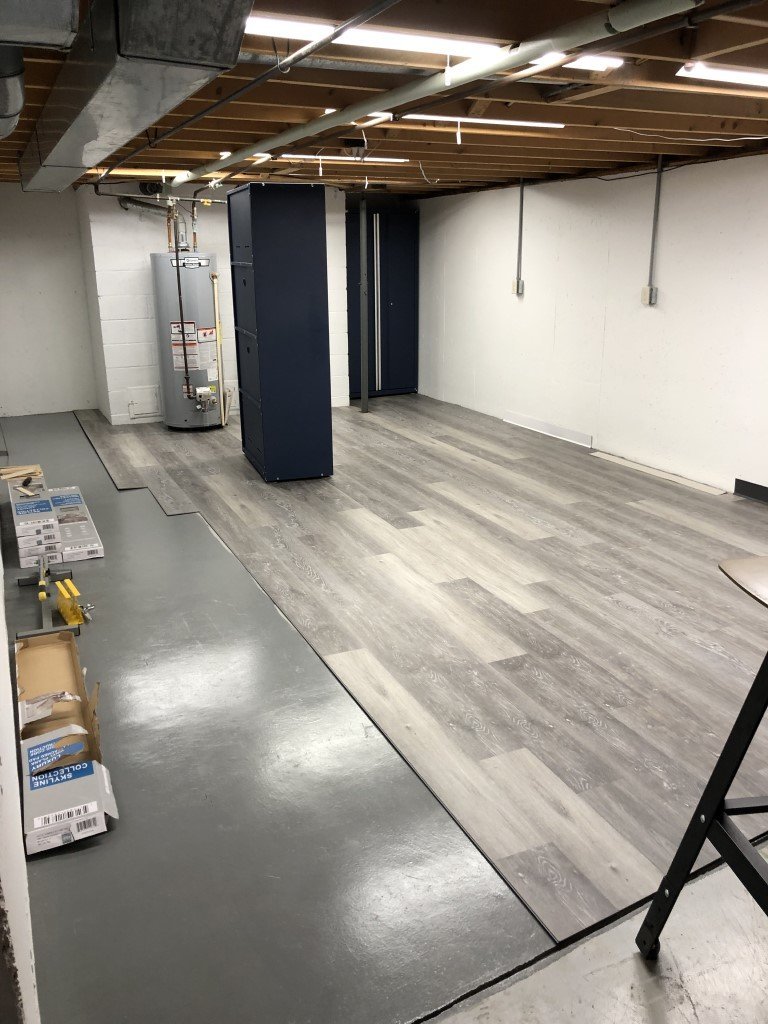
Slow but sure (i.e., haven't been spending a great deal of time with the model lately). Some time has gone to sprucing up my basement power tool area. It is region about 14' x 20' in terms of useable space. There are also indentations at the back where some nice cabinets are going. The flooring is all in now, but a bit of wall trim is still needed before moving everything back in. I'm also suppose to put up some kind of sound barrier on the open end - apparently there is some noise that makes its way upstairs!
- Paul Le Wol, clearway, Keith Black and 1 other
-
4
-
I've installed the chainplates (and painted the mid-portion of each to match the upper hull color) on the port side of the model.
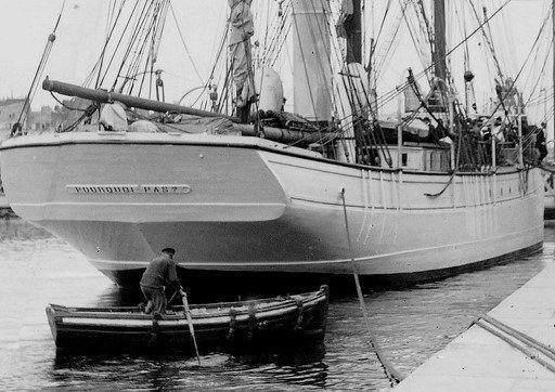
I've tried to mimic the method of chainplate installation used on the actual ship as opposed to the method presented in the instructions. In the following image, you can see that the chainplates do not come into contact with the hull between the two guard rails - this is how I've placed the chainplates on the model. I wish I had seen this picture much earlier in this build as the upper guard rail location is much higher than where I placed it (based on the kit instructions).
On to the starboard side! Once the remaining 21 chainplates are in place, I plan on adding the eyebolts need on the deck and on the hull exterior.
The kit instructions call for the model builder to bend the chainplates over each of the guard rails in a way that brings the chainplates tight to the hull in three locations.
On to the 21 starboard matching chainplates. Once they are installed, I plan on making and installing the deck and hull eyebolts as well as the lower 42 deadeyes.. After that, I expect that making and fitting the bowsprit will be in order. So many 'little things' to be done before the rigging begins!
- Keith Black, clearway, Paul Le Wol and 1 other
-
3
-
 1
1
-
Keith-
That is exactly what I was planning on doing!
Thanks for alerting me to your new HMS Erebus build - looks like the initial work is going nicely and swiftly.
- clearway and Keith Black
-
2
-
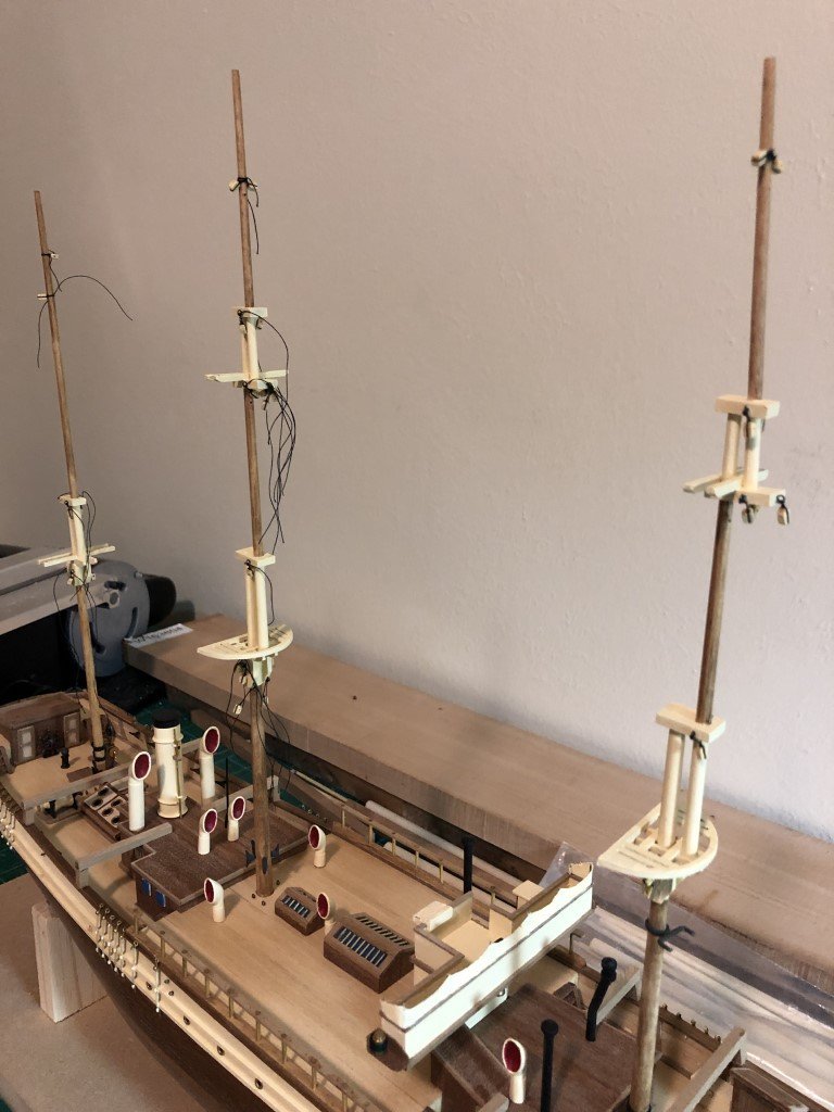
Slow going lately - family visits and house projects have taken precedence! But the lower masts and tops are done, as well as painting a couple of the doublings. I should be able to get a good feel for where all the chain plates belong now. I think that I should do that work before extending the masts as the top portions will be fragile before rigging is added.
- ccoyle, clearway and Keith Black
-
3
-
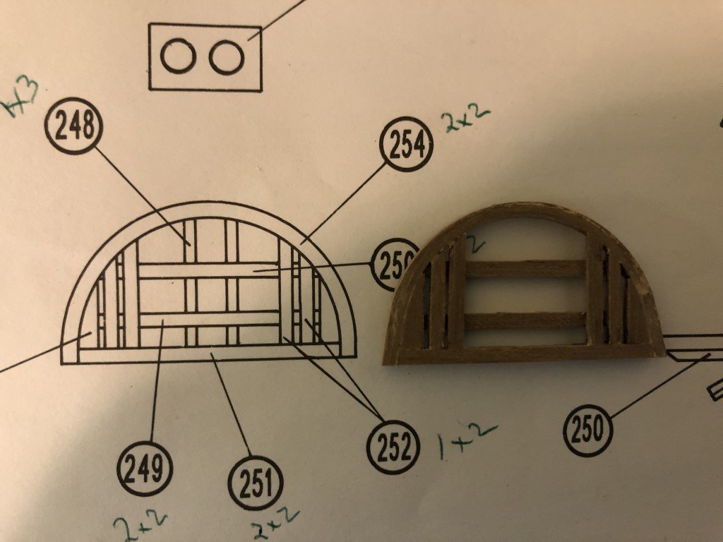
The last couple of days I have been working on the fore and main mast tops. It has been taking more effort than expected. Bending the 2x2mm material to create the outer edge has been problematic for me. A lot of heat and water, but the wood has been quite resistant to bending into the correct shape. To help for this shape I made a mold to let the bent wood dry inside of for a day. This is (hopefully) going to be the piece needed for the second top.
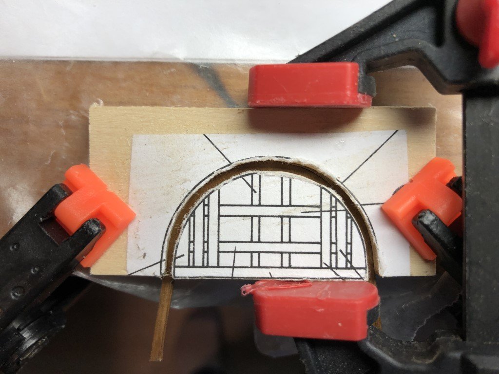
The first top doesn't look too bad. I don't think I will be able to do better with the supplied material, so it is going to become part of either the fore or main mast in the near future.
- GrandpaPhil, clearway and Keith Black
-
3
-
I know its been awhile and I had said I would be spending more time with this model; however, I started another and got a bit caught up in the new build. After finishing the dredger model, my confidence level went up a notch and I started into building L'Invention from the ANCRE monograph. It's a big project - a four-masted privateer constructed in 1799 - and I'm having fun with it, but I need to get this one done and gifted.
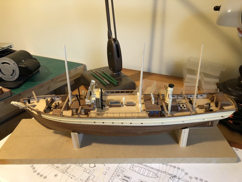
Over the last couple of days I fitted cleats to the bulwarks - while doing this, I admonished myself a few times for not putting them in before the deck furniture! Skids for the two fore and two aft ship's boats are in place, as are the six ladders for going from deck to deck. I've also started on the lower masts. I want to get the masts assembled so that I can better locate the positions for the chain plates. After going back and looking at photographs of the actual ship I noticed that the chain plates should thread through the rails. I wish I had made that observation earlier as I could have made slots when I was laminating the rails. Now I can't think of a way to introduce thin rectangular slots in rails that will have a really good chance for success - there are 42 chain plates to deal with. So either they are going on the outside of the rail or I will make notches in the rail for them to be embedded.
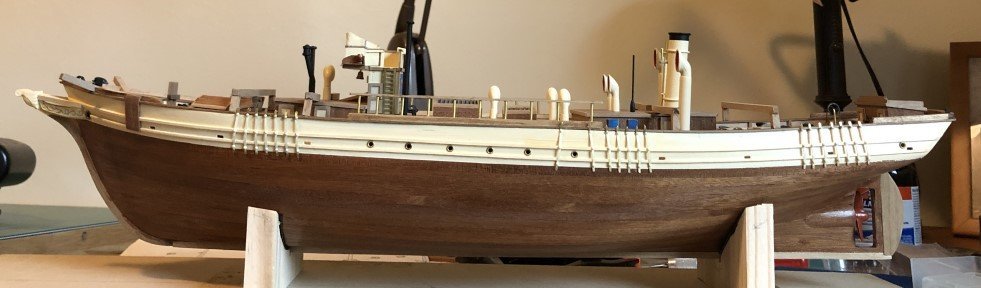
I guess I'll need to make a decision soon. In the meantime, here is how Le Pourquoi-Pas? looks this evening:
Hopefully more soon!
-
Here the final 5 Type B frames are drying between glass plates. So all 34 of the type A and B frames are now assembled.
Now I can decide between preparing more 4mm thick material and assembling the Type C frames or spending some time standing at the spindle sander and finish sanding what is already assembled. This evening I'm thinking the spindle sander might be a nice change of pace!
- GrandpaPhil, KARAVOKIRIS, davyboy and 8 others
-
11
Santos Dumont 14 bis (1906) by Greg Davis - Model Airways - 1:16 scale - Finished
in Non-ship/categorised builds
Posted
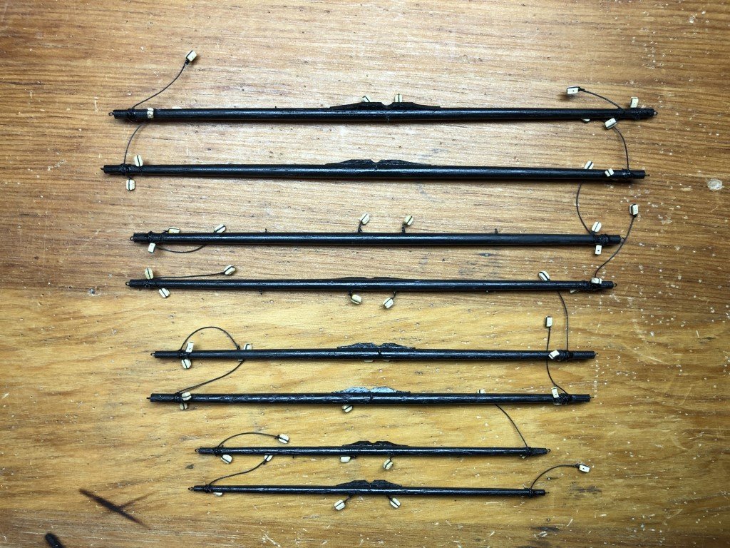
All six of the wing panels have been glued up now. I am worried about how strong these will be because of all the butt joints - are the panels going to collapse when they are incorporated into the wings? When I made balsa planes as a youngster I never worried about this and really never had too many failures; however all the planes were covered with tissue paper / silkspan or other types of coverings. So I have been trying to think of a reinforcement scheme that would be approprite for the model. I did find a couple of references that claimed that there were 'aluminum fixtures' used in construction of the actual plane. What these looked like I do not know. It also is reported that the original plans (and plane, except for the basket) no longer exist. All current plans are reconstructions based heavily on photographs often using the basket as a means to scale dimensions of the plane. Here is a link to a (what I think is a very informative) paper about the 14 bis https://www.fzt.haw-hamburg.de/pers/Scholz/ewade/2007/CEAS2007/papers2007/ceas-2007-065.pdf .
Here is a pic of the six matching wing panels:
I'm going to set these aside for a while until I finalize plans for replication of bamboo nodes (or not including them) and possible reinforment of the butt joints. Pinning the joints is out of the question. I am wondering if drilling small holes thru the dowels on both sides of the joints and then tying the pieces together would be a way to go. I don't know how isuccesful I would be in doing this and how intrusive the result would look.