


Greg Davis
-
Posts
711 -
Joined
-
Last visited
Content Type
Profiles
Forums
Gallery
Events
Posts posted by Greg Davis
-
-
Today I began to work on / solve the exhaust pipe installation process. The pipes have quite a few bends and need to connect to a short stub on the cylinder castings. Several very failed attempts before getting to this version of which I've placed on two different cylinders to see how it looks:
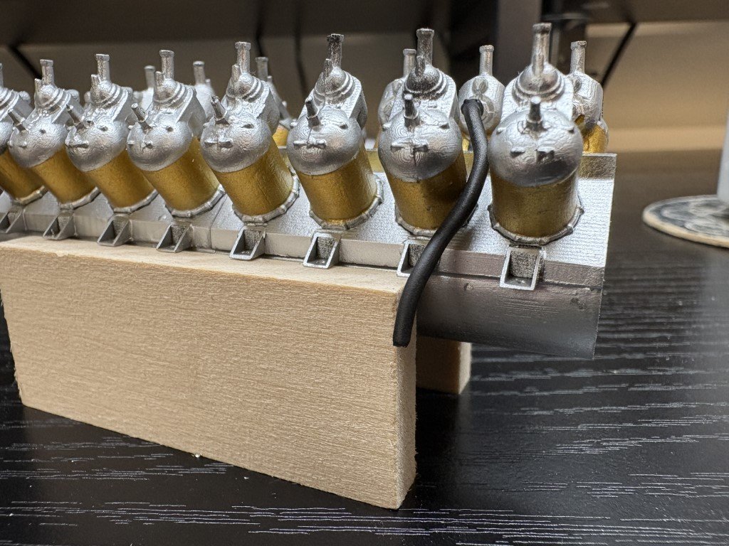
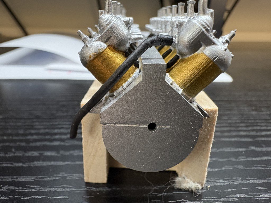
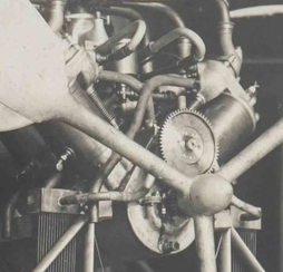
The shape is getting close (should be flat a bit longer across the top and there's a small blip in the tubing that I didn't shrink out well enough), but this is what the pipes are suppose to look like:
This one has a 1/16" brass wire rod as a core. A short bit of brass tubing soldered to the start to form a coupler with the cylinder casting stub. Finally, black rubber shrink tubing was slipped over the wire and shrunk. I made enough attempts trying to bend brass and aluminum tubing to the exhaust pipe shape to believe that will not be an effective method of fabrication. Given that the exhaust pipes will be buried amongst other engine accessories I'm currently thinking that this may be a reasonable way to make the 16 needed pipes.
Thoughts / comments?
-
Today's accomplishment was coating all of the wood with linseed oil - there is more surface area than you would expect!
This will need to dry / cure for quite awhile. While that is happening, I plan to turn my attention to engine work.
- steamschooner, Canute, Keith Black and 12 others
-
 13
13
-
 2
2
-
-
-
Today's little project - a saddle to sit on:
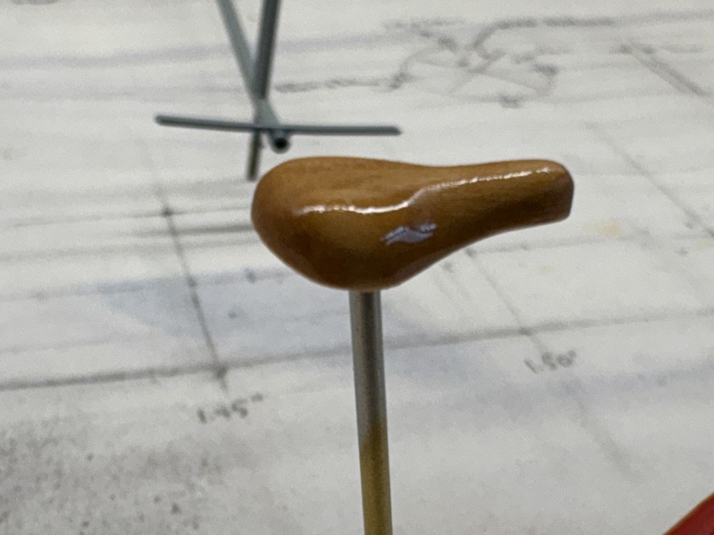
It was shaped out of C Boxwood and is approximately 1 x 1.5 cm. Right now the saddle is shiny because it was just coated with linseed oil.
- MAGIC's Craig, Keith Black, mtaylor and 9 others
-
10
-
2
-
A couple days of work on the steering wheel has gotten me to here:

First I cut and milled a piece of brass to serve as the spokes of the wheel together with a rim. Two pieces of C Boxwood with a circle cut out were used to sandwich the brass piece - all attached with epoxy. Then the exterior was sanded to about the correct diameter. Sanding the wheel to a round cross-section then followed. A few more details to add, but this is what I'm trying to mimic:
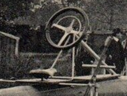
I feel that I am getting close - probably as close as my skills will allow!
-
Here's my start on the cockpit. I've made the platform, the steering column structure and the footrest. I'll trim down the parts that go thru the cockpit after they have been attached.
Still to come the saddle / seat and the steering wheel (doesn't look easy at all, ugh!).
-
I have not lost interest in this model, but I have a few other projects going on and like to go back and forth at times! One of the projects, the Santos-Dumont No 18 Hydroplane has elevated to the top as I would like to take it to a modeling contest in mid-May. I will be spending most of my time on that; however, every model has its downtime for one reason or another and that will be the time that Phantom and my OcCre BR 18 Locomotive projects get for the time being. After that who knows - there must be 30+ models in the que!
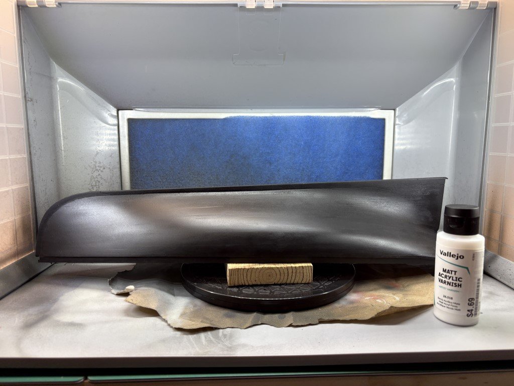
Finally 'fixed' the paint issue, and today I applied the first coat of varnish to the hull. It will get another tomorrow and then it will be set for marking the waterline and some copper.
- ccoyle, JacquesCousteau, yvesvidal and 4 others
-
7
-
4 hours ago, KeithAug said:
All looking rather nice. It would appear that the foils were quite small.
Yes, they don't seem to have a large chord. I've done my best to interpret a number of photographs and then made them with a 2cm chord - that would make them roughly a foot in reality.
- Keith Black, KeithAug, Canute and 1 other
-
4
-
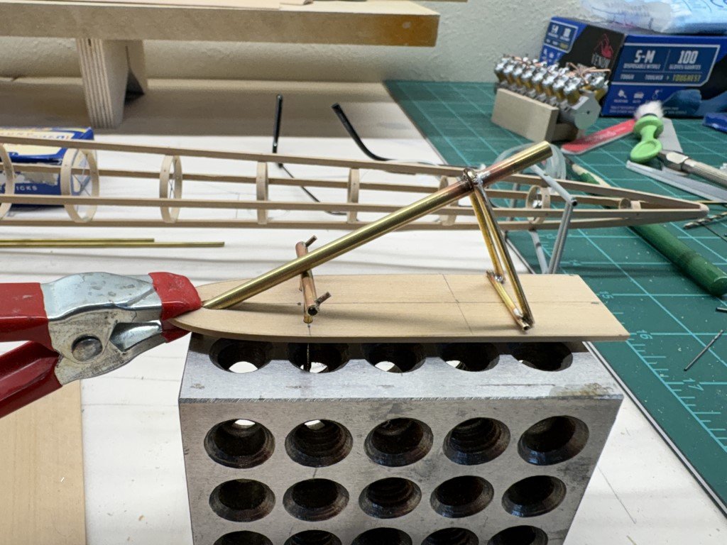
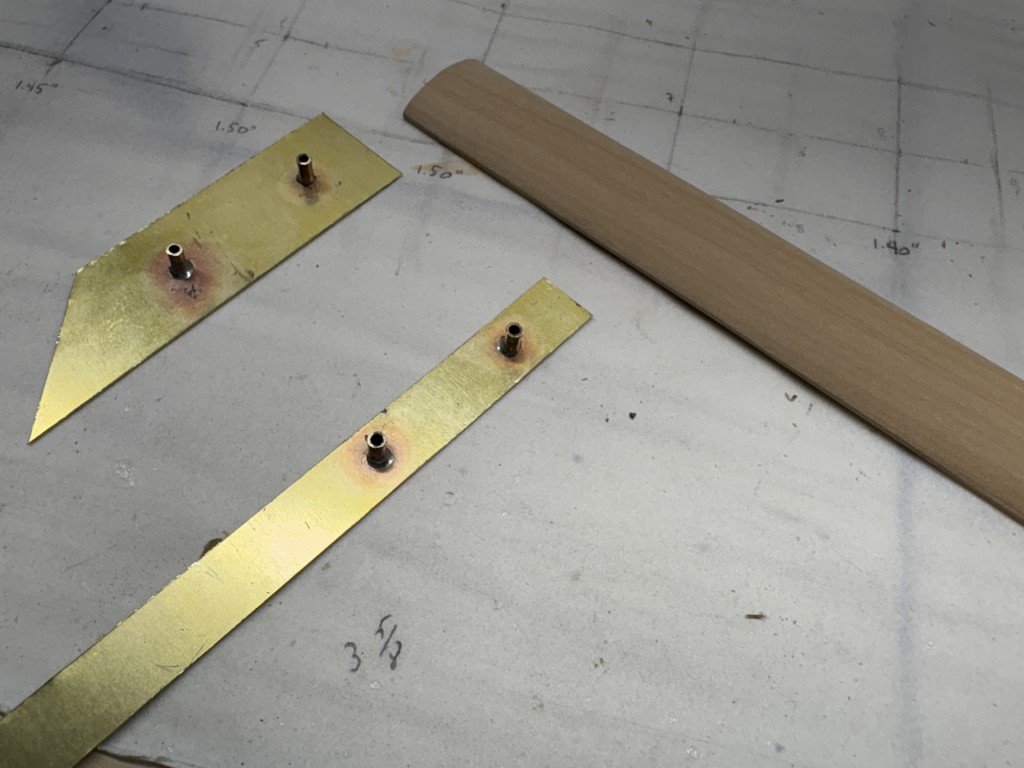
I made a small jig to bend the hydrofoil shape into the brass. I added a brass rod to the jig so that the tubes in the attachments would be in the same fore-aft location after being bent.
The four attachments are getting close to their final shapes now - just a bit more adjustment mostly to correct 'spring back' from the initial bending. Here I'm taking a look at how they fit to the hydrofoils when mounted on the boat. I've added all the subcomponents I have finished for this picture as I was curious on how the whole piece of work was coming together.
-
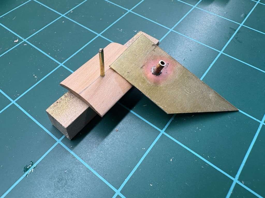
Just a bit more progress for today - this is the start of the attachments that will hold the hydrofoils to the pontoon harness and the rear metal work.
The brass sheet was drilled to the diameter of the brass tubes and then the pieces were soldered together. The brass sheet will be bent/fitted to the hydrofoil shape on this spare piece of shaped wood. Then I can trim them up for a good fit to the actual hydrofoil pieces. The thin ones are going in the back and the wider ones in the front. I'll paint these to match the other metal structures.
- GrandpaPhil, mtaylor, Canute and 4 others
-
7
-
7 minutes ago, iMustBeCrazy said:
Greg, I hate to ask but how are you going to cover the pontoon?
Craig -
No I am not covering the model - it will be done as a framed model.
With that said, I have considered using the turned pontoon and nacelles (that I made to 'test' my plans) to make a second model at some point. That model would be completely painted and would show no internal components. However, this is pretty low on my to do list!
Greg
- iMustBeCrazy, Canute, KeithAug and 2 others
-
5
-
11 minutes ago, KeithAug said:
Yes, that seemed to be sensible to me Greg. However a symmetrical design for a display model is much more aesthetically pleasing.
True - and we're not trying to redesign this iconic hydroplane!
- KeithAug, Keith Black, mtaylor and 1 other
-
4
-
21 minutes ago, KeithAug said:
Greg. It would be interesting to understand what the angle of the centre line of the engine is relative to the centre line of the hull. Clearly with it being mounted so high the tendency would be for the moment of force to push the bow lower in the water. This of course could be counteracted by angling the front of the engine up relative to the hull. Also the torque reaction is going to force one of the sponsons down and the other one up. This could be counteracted by moving the centre of gravity of the engine to one side. I can't tell from the phots whether Santos took any of these points into account. Do you have insights?
In correspondence with Professor Catalano, a professor of aerodynamics at the University of Sao Paulo and Santos Dumont researcher, he wrote: 'He was unsuccessful after the powered model lateral instability in water.' After reading this, I thought of the problems WWI fighter pilots had with torque from their plane's engines. From a physics perspective, mounting the engine on a pylon would only serve to make that type of problem worse. I then wondered why he didn't try to correct this using an asymmetric design. I didn't think of moving the engine, but rather moving one of the outriggers / nacelles further away from the main pontoon. I'm also guessing that the reason we have discussed the cockpit location was partially due to the instability problem - leveraging his weight further to the rear would have helped with the bow getting pushed down. I have no idea why he ultimately gave up on the project - perhaps it just wasn't as interesting as flight to him!
- mtaylor, Keith Black and Canute
-
3
-
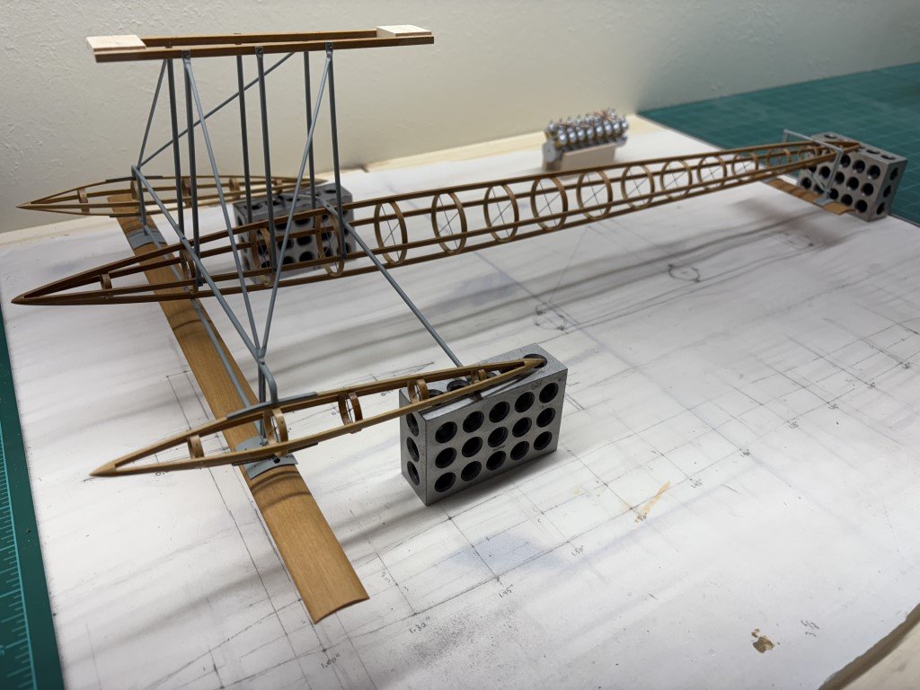
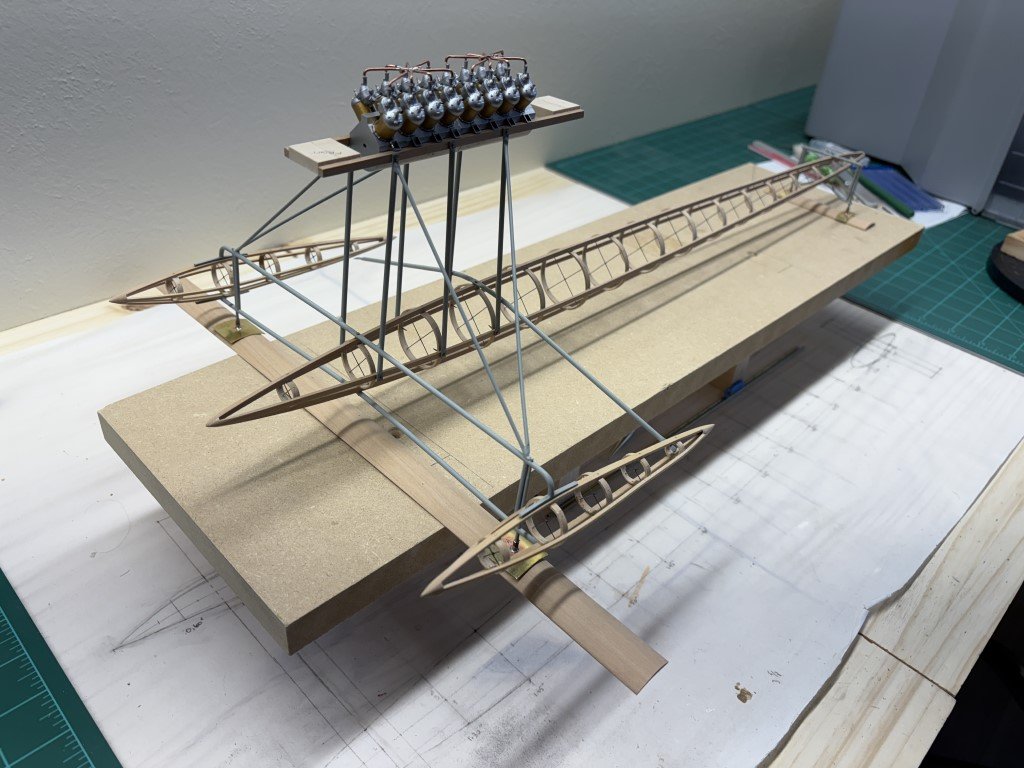
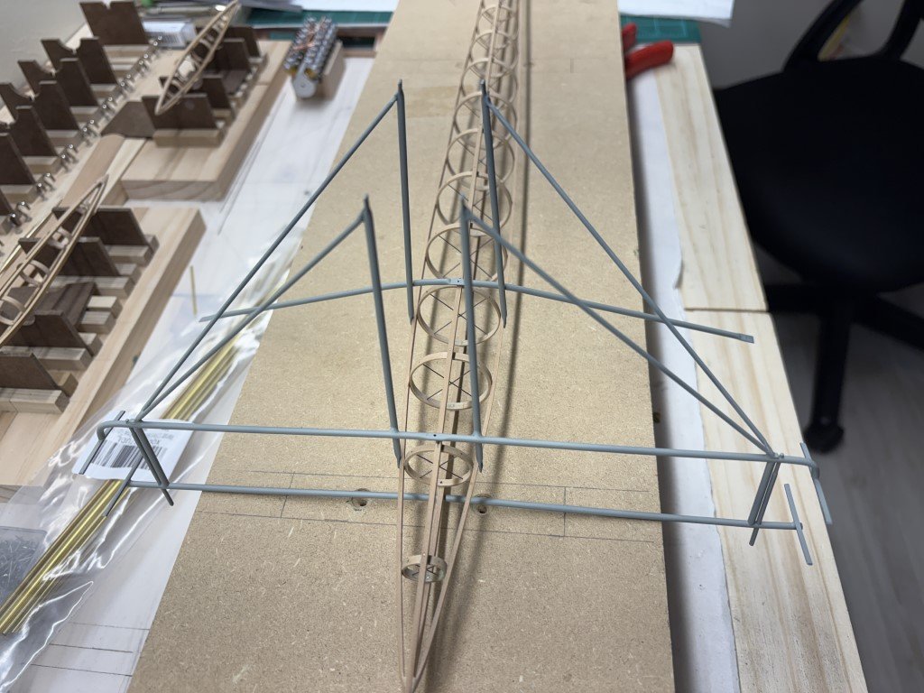
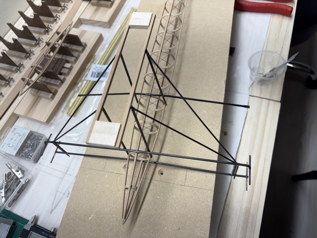
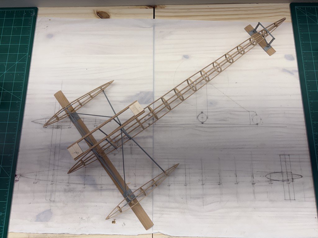
Got a bit excited and needed to post a picture! The harness is now permanently attached to the pontoon. The wooden engine mounting strips were drilled to match the mounts on the engine block. The strips currently are spaced by blocks and are overly long - they will be reduced to the correct size when it is time to secure the engine in place. Here I have test fitted / set the engine in place and was quite satisfied to see that the harness is plenty strong and everything seems to line up as needed.
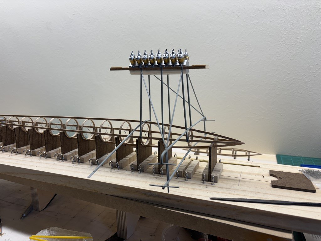
I'll be able to continue some of the work with the model set on the original building jig. I had not glued the supports so that they could be removed for special purposes. Here the second support is removed and there is actually space to mount the hydrofoil below without interference from the jig. The second support from the rear has also been removed so that there is space for the rear hydrofoil mounting structure.
Onward we go - it is nice to see the subassemblies fitting!
-
Thank you Craig for all the help you are providing!
I looked more at pictures of the boat and decided that the pontoon harness should be lighter in color than the blue/grey pontoon and nacelles. So I've gone more toward the grey tone with a touch of blue.
I looked though all the blue and grey offerings in the Vallejo Model Air lineup and went to the local Hobby Town and picked up a variety of possible colors. Did some tests on brass tubes to see what they looked like as well as how they matched up with the other materials used in the model. Finally decided on using Vallejo Model Air Grey Blue:
Here's what it looks like now:
I think this looks much better than when it was blackened.
- Canute, GrandpaPhil, wefalck and 9 others
-
12
-
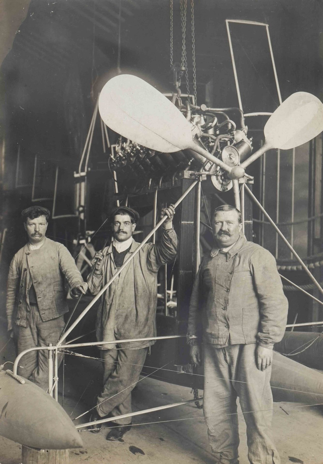
9 hours ago, iMustBeCrazy said:
I've had a look and a long think and my 2c goes to painted steel.
The following two pics tell the story, the suspension upright and the bent support are bare metal in the first pic, both are the same colour and not aluminium.
In the second pic the suspension upright looks like bare steel at the top and except for that bit both are now coated in a pale colour (it could be any pale colour, pale grey, pale blue, pale yellow, pale red, pale green, any pale colour) but not white.
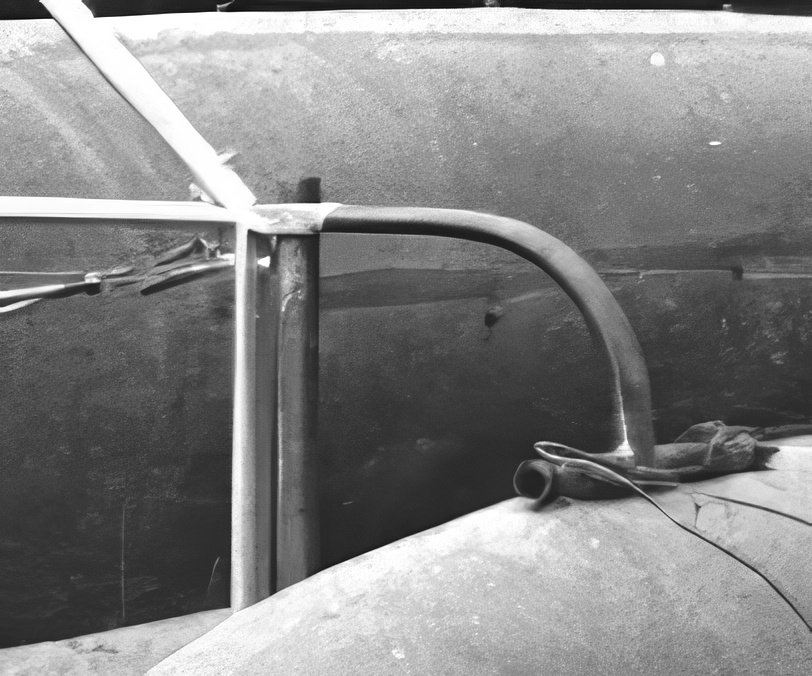
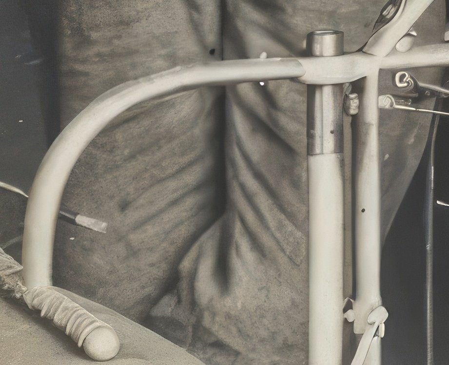
The other struts with the flattened ends, well aluminium doesn't like that unless it's soft and then it bends really easily. It could be done but I suspect not.
Steel bicycle tubing seems the most likely.
Craig -
Amazingly clear images - how do you do that????
There are some references to the hydroplane in terms of coloration - light blue / bluish-grey had been reported.
I'm waffling on the color I'm going to use.
Greg
-
Here is the wood framing for the cab. The six pieces slot together nicely. Note how the bottom of piece 40 goes across the cab floor. Once the glue is dry, that strip will be removed - while not noted in the instructions I was careful to not apply glue down there!
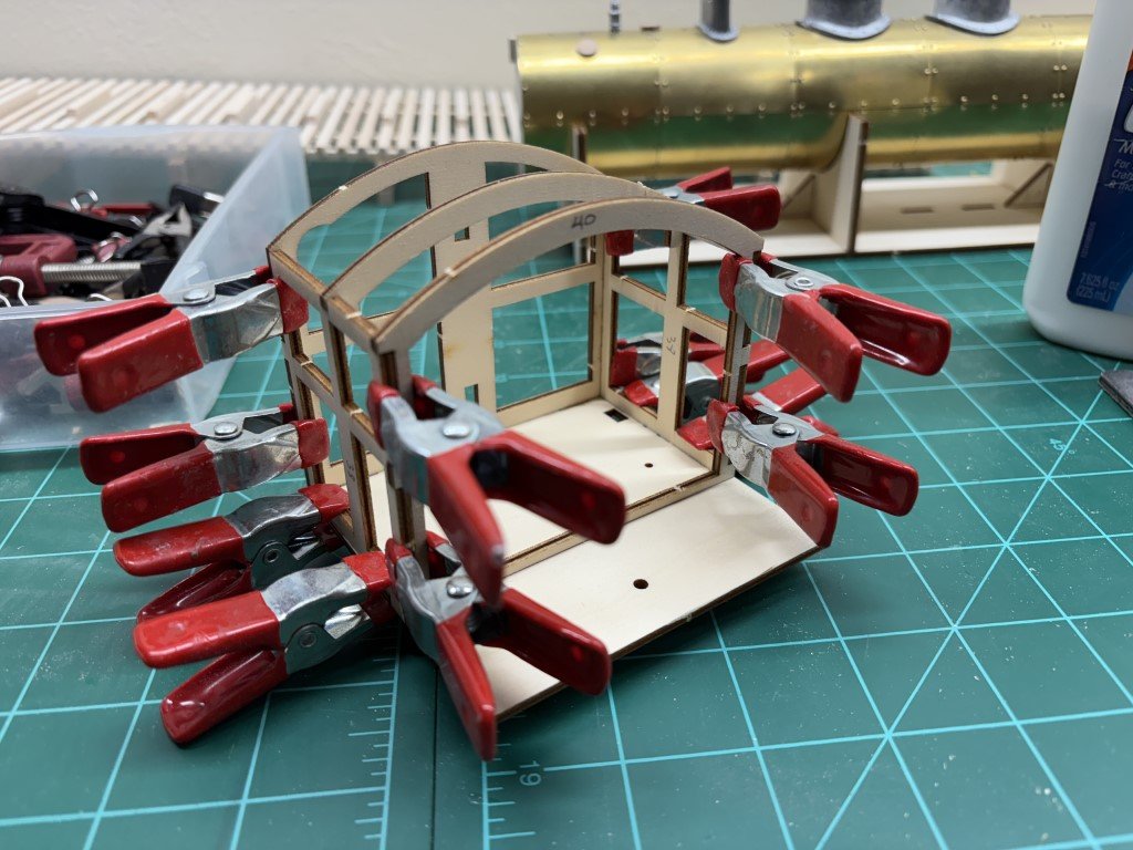
Later the exterior of this structure will be covered with bass sheeting.
-
1 hour ago, KeithAug said:
It is going to be very delicate once finished. I think it will need a case.
Yes, that is a good idea. If all goes well, I would like to have the model finished by mid-May so that I can bring it to a model boat and ship contest that is held about a hours drive from my home. It would be unfortunate to have it damaged in transit and/or by touchy fingers!
-
5 hours ago, AON said:
Could it have been galvanized pipe?
That does seem reasonable, now that you mention it! Months ago, I had looked into the history of aluminum tubing and it didn't seem to fit quite right for the time period. So I did then think more about steel tubing as it was being used in the bicycle manufacturing process and it is said that SD had made use of bicycle wheels from Peugeot on the 14bis. Related, the steering wheel on the hydroplane may be Peugeot as well. Anyway, I hadn't thought about galvanized steel - the zinc coating would give the lighter color and importantly the rust proofing for his creations!
- Keith Black, mtaylor, druxey and 1 other
-
4
-
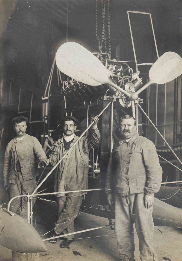
11 hours ago, KeithAug said:
The aerodynamics of the prop leaves a lot to be desired. It looks like they made it out of some left over canoe paddles. It is surprising how light weight the framework is. Are you planning to install the bracing wires Greg? I think you are right about the colour of the frame.
Yes, I will be 'rigging' the model.
It seems that SD really liked the big aluminum propeller blades. From the pictures of his machines that I've seen, the only craft that used a more modern two-bladed wooden propeller was the Demoiselle - his final airplane.
- Canute, Keith Black and mtaylor
-
3
-
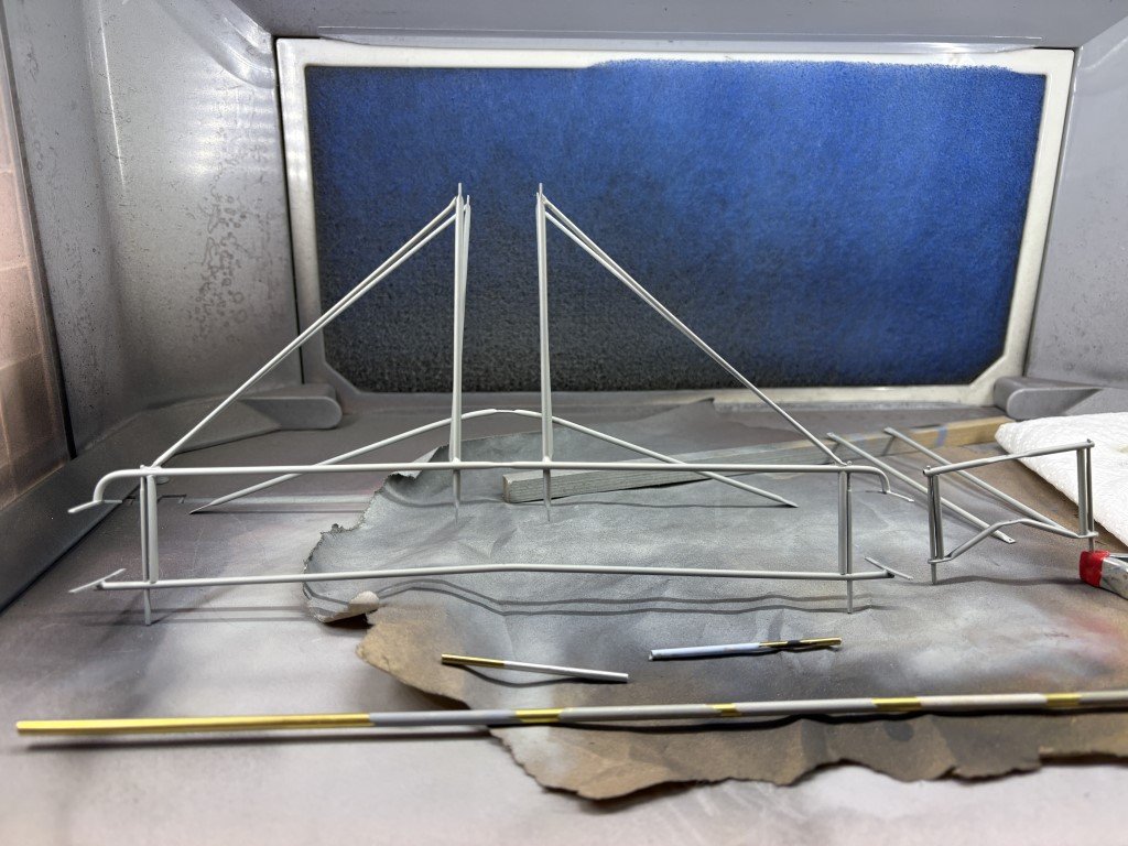
A while back I chemically blackened the pontoon harness.
I've looked at it for days - disliking it more and more. Today I stripped the structure back to clean brass. I'm now going to prime and then paint it aluminum. Hopefully that will get this back to a lighter color seen in photographs of the craft:
I've spent a lot of time wondering as to what metal was used in the boats construction - steel, aluminum, other. It is known that the propeller is aluminum and the color of the pontoon harness / engine pylon seem to be similar. Blackening was not good; hopefully painting is better!
- druxey, GrandpaPhil, Canute and 4 others
-
7
-
I have finished the first phase of the build. All the main boiler castings have been added. The instructions tell me that it is time to prime and paint the boiler!
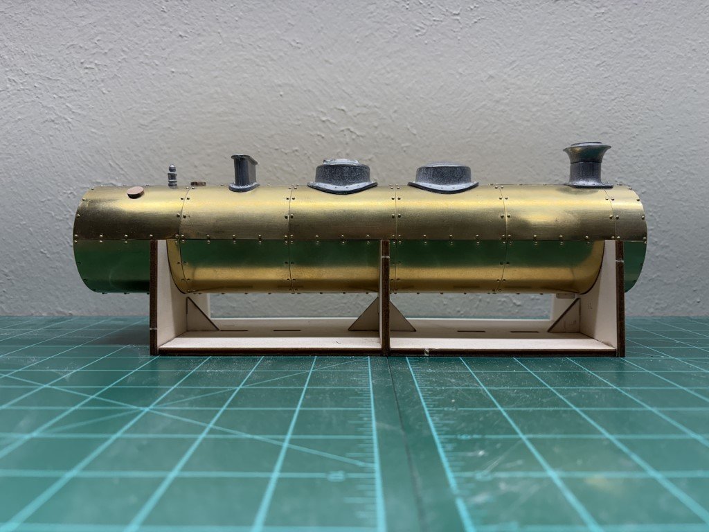
I'm now having reservations about the light blue / red color scheme I had picked at the start - I'm concerned that it may look too 'toy-like' for lack of a better description. Still don't want to have it in green. My feelings are now tilting toward this blue / black scheme:
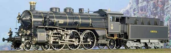
This is one of several color schemes that Micro Metakit has produced the BR18 in. By the way, this HO brass model sells for about $2,300. Yet, some people tell me that making wooden ship (and other models) is a costly hobby!
-
Everyone -
Thank you so much for all the input - I learn so much from all of you!
Greg

Santos Dumont No. 18 Hydroplane 1907 by Greg Davis - FINISHED - Scale 1:16
in - Build logs for subjects built 1901 - Present Day
Posted
I can give that a try - it does sound like it would be easier to do!
Thanks
Greg