


Greg Davis
-
Posts
803 -
Joined
-
Last visited
Content Type
Profiles
Forums
Gallery
Events
Posts posted by Greg Davis
-
-
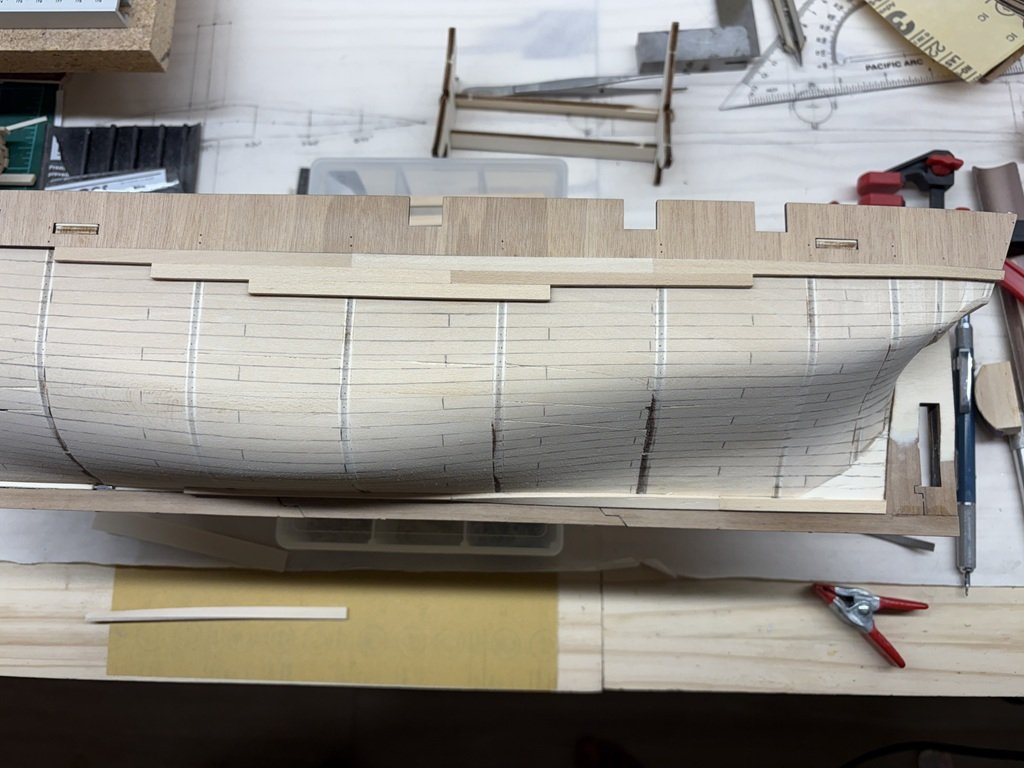
I (minor) milestone - the top and bottom planking work has come together!

- clearway, Nick 843 and JacquesCousteau
-
 3
3
-
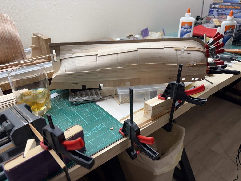
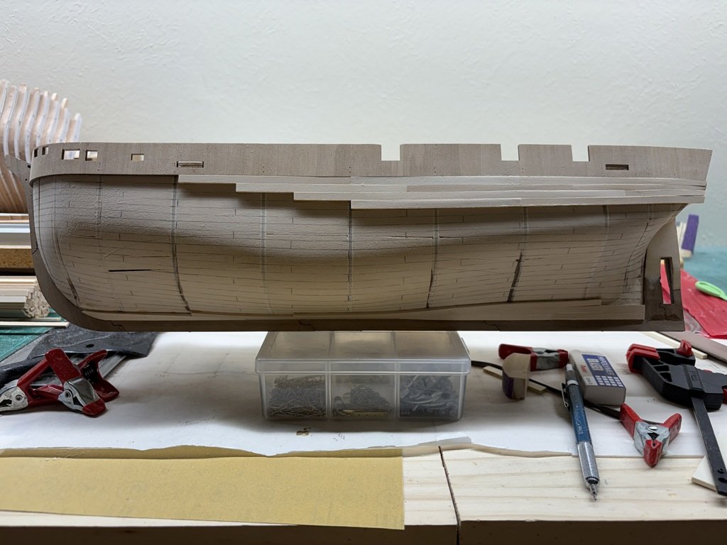
Progress - slow, but sure! One more plank and the top-to-down will meet bottom-to-top work. The plank sitting below the model has been bent in a jig to help facilitate the stern tuck planking.
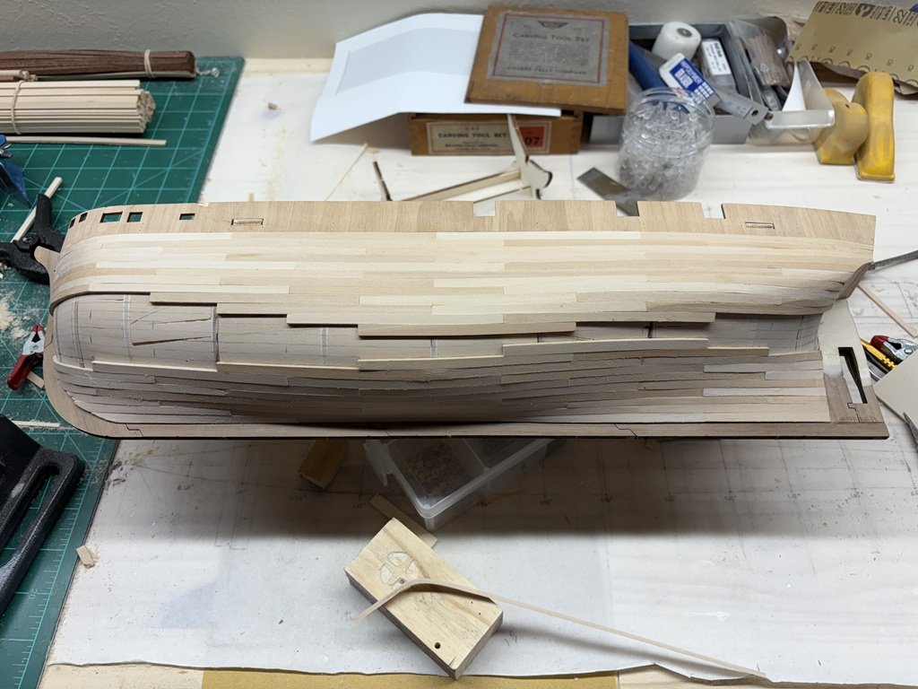
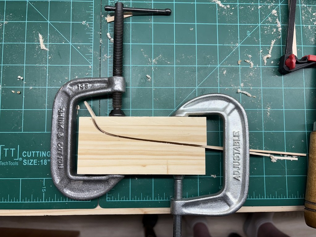
The jig is pretty simple; but, depending on the piece of wood, my take more than one wetting and overnight clamping iteration. The jig is very much like the one Chapelle uses to bend wales in his Ships of the American Revolution book.
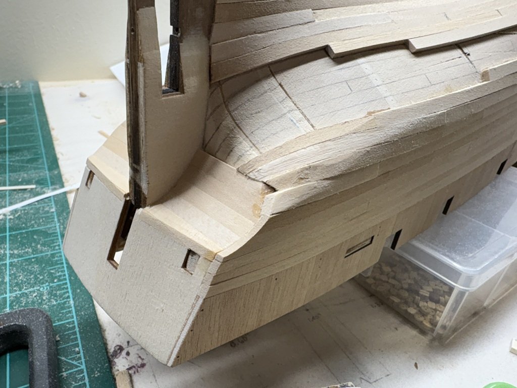
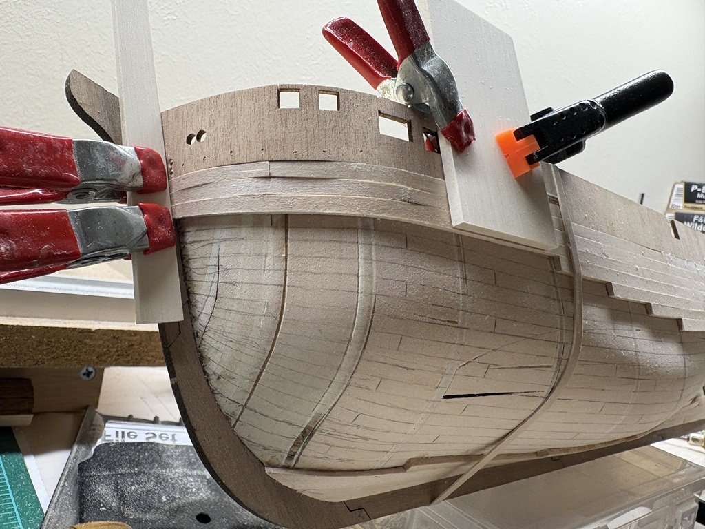
Here's the beginning of the tuck planking being installed:
-
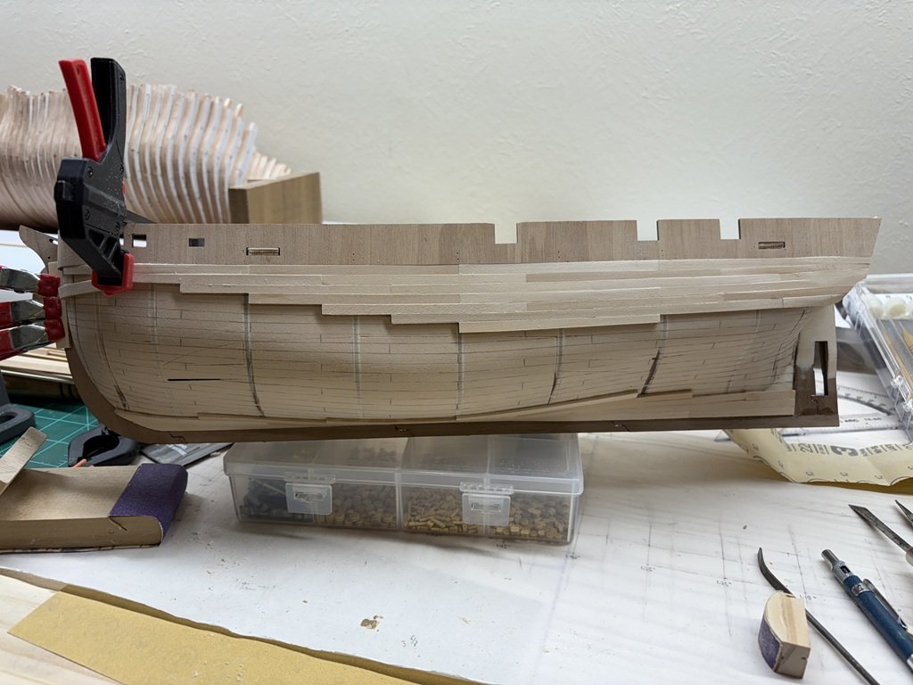
The planking continues! Soon the middle gap will close. I've made a jig to help form the sharply bent stern planks - if it works, I'll post a picture of the jig.
- JacquesCousteau and clearway
-
2
-
8 hours ago, Maid of the Mist said:
A shipwright drinking on the job? Living up to the highest standards of the Royal Navy, I see 🫡
Even more so when I have a bottle of this in the house:

-
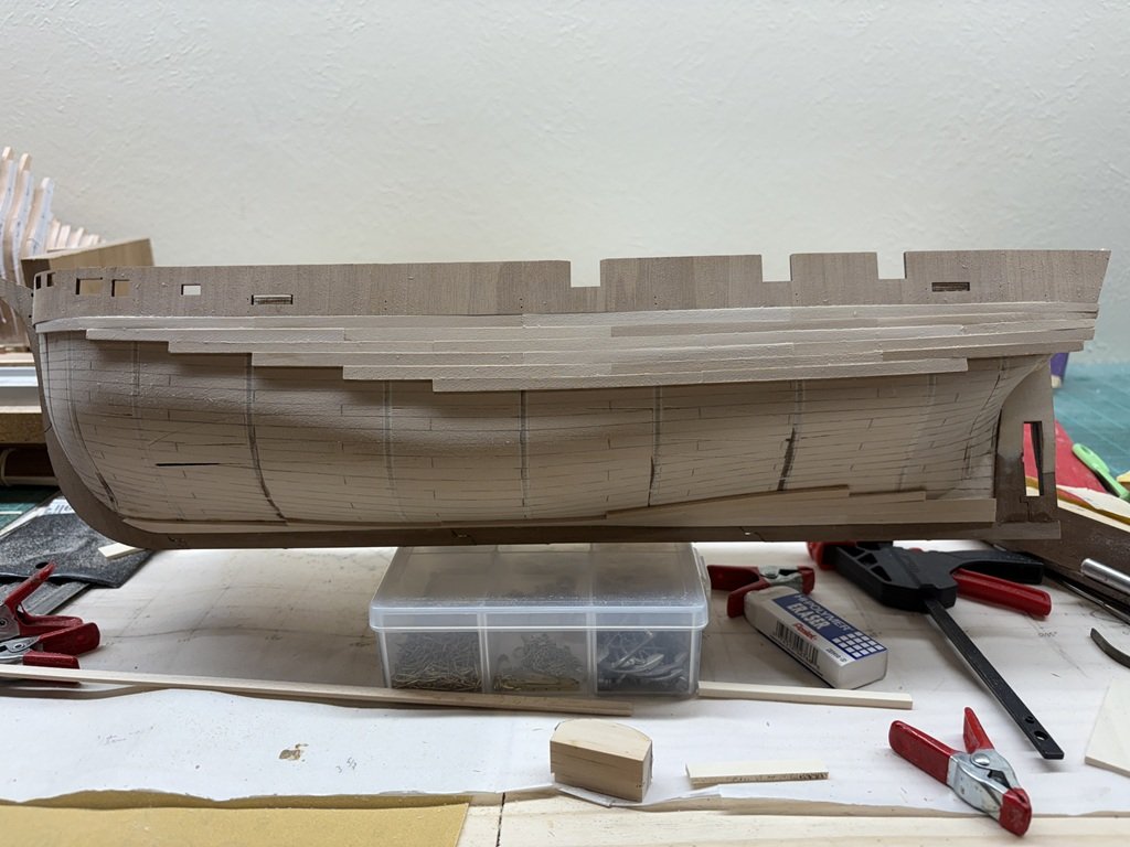
A bit of progress - not as much as I had hoped for; however, I've spent a good deal of time over the past week creating a PowerPoint presentation on building model ships that will be delivered to an audience in the Learning in Retirement Program at the University of Wisconsin - Green Bay. Hopefully the talk will encourage a few to take up the hobby!
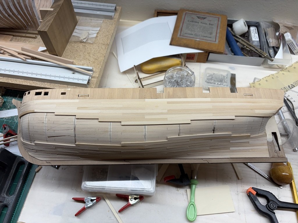
Anyway, here is Terror as of this evening:
Four planks are being pre-bent to take up positions near the stem and stern (top and bottom). Not too long before the top and bottom work come together! But still a lot of planks that need sharp bends. The Jameson is helping the process!
-
6 minutes ago, Knocklouder said:
Just wondering if you have an electric plank bender, I found it very useful 👍🏻
Bob M

Yes I do, but I don’t tend to use it as much as I could! For these planks I’ve been experimenting with water and a hairdryer in a manner similar to that described in Chuck’s Chearful instructions chapter 4.
-
So far only 3 planks today ☹️. But they were hard ones that butt up against the stem. I needed to partially form each, then wet to bend, and do some more shaping before they could be attached. Once the now clamped plank dries I will be able to add quite a few planks with less difficulty going front to back and downward.
Yesterday I got about 10 planks attached and cleaned up the back edge of the top 6 stakes. In the back, it is time to work on the tuck. There is quite a bit of bend in that area and I am debating the wisdom of creating a mold to bend the planks in that area.
-
1 hour ago, Maid of the Mist said:
I’m still fairly new to the hobby, so my experience with paints is limited. That said, I’ve found the OcCre colours to be excellent, provided they’re the shades you actually want to use. A little really does go a long way. Those small bottles hold far more paint than you’ll need to finish a ship, probably three times as much.
I bought the Beagle paint set from Amazon.co.uk. It had the exact same product code as the one listed on OcCre’s website and came in identical OcCre packaging. So the mystery remains…
If I do have one criticism of OcCre, it’s their instructions. Yes, they provide plans, photos, and YouTube videos but many important details get left out. I often only notice these subtleties after I’ve already glued a part in place, which means reworking it. Clear, thorough written instructions in proper English needn't be the preserve of high end manufacturers like Vanguard.
Good to hear that the paint is of good quality.
I agree, they are not great with instructions; either written nor with their photo collages. The builder really needs to continue to look at the pictures throughout the sheets of paper and determine a course of action. Certainly it is clear that some construction must come before others, but in some cases the builder must make adjustments and / or choices (best guesses) as they proceed. It doesn't seem that it should be that difficult for each and every model company to produce a solid set of instructions that are straightforward to follow. Its not even a question of language - I don't see that those that read Spanish would be any better off with the Occre instructions! Either way, I still think you are making very good progress with the model.
-
On 7/28/2025 at 8:54 AM, Stubby said:
Great build and very detailed log. Marked for reference.
Thank you very much!
-
On 7/11/2025 at 2:20 AM, Wawona59 said:
Hi Greg,
I'm glad that you got to visit the hydro museum in Kent, very interesting place for a hydro fan. The hydroplane races on Lake Washington were a big deal when I was a kid in the 6o's. Well, this evening I dug out my Slo-Mo-IV kit and began cutting out and dry fitting the laser cut frames. The laser cutting on my kit is very precise and well done. This evening, I got all of the bulkheads cut out and dry fit. Now comes the sanding and fairing. I probably should start a build log.
This will be part of the Seattle-based models I'm planning to build, including the 1/96 West Coast Lumber Schooner that Bluejacket is currently developing.
Are you planning to build your Slo-Mo-IV as static or RC? PM me if you get a chance.
Good to hear the parts go together nicely! Yes, please start a log as it would be great to see your progress. The Lumber Schooner looks to be a really nice topic as well.
I did buy the RC equipment along with the kit, but I'm not sure if I will use it or not. I'll PM you when / if I get to building the machine and start a log.
Greg
-
On 7/15/2025 at 4:28 PM, jac harnett said:
Hello
Please tell me what adhesive did you use on the cast parts? I did do a hot soap and water wash. I have tries JB weld fast and slow, epoxy 5 and 45min as well as standard CA. Hothing has held for me.
I'm sorry to have been so slow to respond - I used medium CA to glue the engine castings together. Fresh CA worked well for me, but I've found that if the CA is old it is iffy in terms of the adhesion you may get. In a number of places I did need to file the castings so that the joint locations were tight to one another.
- Jack12477, Canute and Old Collingwood
-
3
-
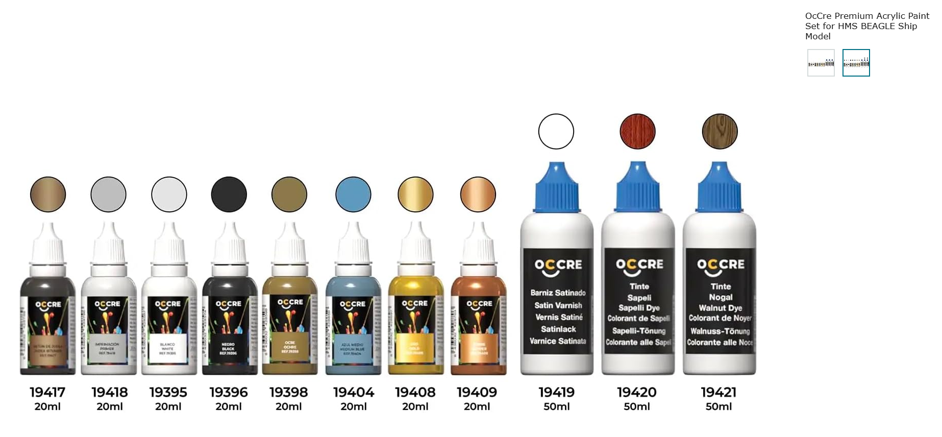
I curious as to where you obtained the paint set.
Interestingly, on the Occre site, the Beagle paint set is like what you received (probably were out of the smaller vial of blue and made a substitution):

But on Amazon, the Occre Beagle paint set is a bit different from what you receive. It includes the Walnut dye and two additional paint colors; also, it is a little cheaper ($51.29 with free shipping).

When I first started the hobby, I did by paint sets matched with a couple of models (Model Shipways) but was rarely satisfied with what I obtained for various reasons. Similar to DonSangria, I now tend to obtain paints and stains individually as I desire them for my models. I've never used Occre (EarthMark) paints so I'll be interested to see how you like them. Currently I'm using Vallejo acrylics - they have two lines Model Color and Model Air. Model Color can be brushed and thinned for airbrushing whereas Model Air is specifically for airbrushing and does not go on very well with a brush. They offer a huge range of colors and are relatively easy for me to obtain.
-
After 3 days, 30 planks are now in place. About 85 more to go on this side. My count of planks was way off a couple of days ago - there are closer to 115 planks on each side rather than 75!
Soon the work will get more challenging coming down from above as for the next diagonal from the front will have me planking right up to the stem, thus a reasonably sharp bend will need to be put into the plank. Probably as, or more, challenging work coming up aft as in two stakes I will be into the 'tuck'.
Not sure if the work coming up from the bottom will be significantly harder than now. In the front strakes will need to conform to the stem. In the back everything needs to be worked up to the stern post. Some of the planks need a great deal of twist as they make there way to the back.
Here's how far I had made the day before:
-
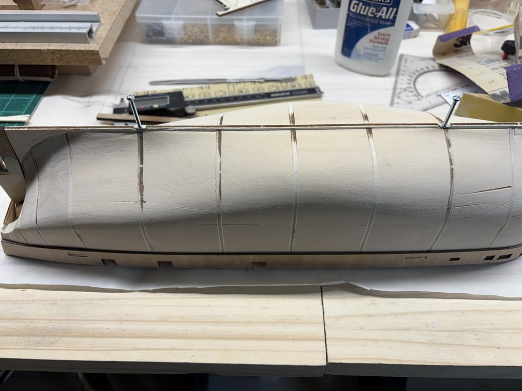
I got 9 planks shaped and installed today - so if things go well / at about this pace, i should be able to plank the hull in about 3 weeks.
I'll most likely plank the complete port side and then go do the starboard planking. I will be working from bottom up and top down simultaneously with the final planks going in near the turn of the bilge. The six planks on top were easy to work, but the lower garboard strake is only partially done due to the twists in those planks. There is one more plank on the garboard strake that is being worked on currently - the one that ends at the stern. It is challenging because it twists 90 degrees in less than 4 inches.
The planks that need a great deal of bending are being wetted and clamped in place to dry / take their shape. I remember rushing this process in one of my first models. In that one, planks were wetted and bent, but I failed to wait for them to be totally dry before attaching to the hull. Once they dried, I had a good number of gaps due to the wood shrinking back to its nominal dimensions; lesson learned and hopefully never repeated again!
-
Looking very Beagle-ish! Love your waterline tool!
-
The planking shift has been marked and hull planking has begun! First plank, part of the garboard has been attached.
Using the provided planking material, I think there will be about 75 planks needed on each side of the hull. Some of the pieces will be hard to form near the bow and stern. Primarily due to the thickness of the material, I don't know if I will be able to get the kit wood to conform to the needed bends or if some supplemental material will be recruited - time will tell. Sometimes I find it a 'fun' challenge to see what can be done with the provided materials
") .
.

-
19 hours ago, Maid of the Mist said:
Is it more difficult to cut planks to scale length than to use full length wood strips?
If the hull doesn't have too much curvature, then full length strips are not too hard to work with. As the curvature increases it becomes more difficult to wood strips in three dimensions. Working with smaller segments helps with this problem and provides a more scale-like planking of the hull. When gluing / attaching the pieces, smaller segments can be easier to get into the correct position. In either case to get a nice run of planks the pieces of wood need to vary in width to accommodate the changing distances along the hull parallel with the frames/bulkheads. This is a primary reason why a hull can't be planked using all strips of a constant width.
Personally, I find it easier to first determine a hull planking pattern and then use multiple (shorter) planks in each strake.
-
Yes, 3 butt shift with 4” planks that correspond to 25’ planks at this scale will be used.
-
Preparing for planking by laying down plank placements. Looks like 23 strakes will do it using the provided planking material. Still need to draw in the planking butts - probably will use a 3 butt shift - after determining the plank length to use.
- JacquesCousteau, Jond, Scott Crouse and 2 others
-
5
-
I've added the rest of the keel / stem / stern structure. There are 3 mm holes thru the keel for the mounting screws to pass. I made the holes using a 3mm endmill on my mill - due to the thickness of the keel there was very little room for error so I didn't want to freehand the drilling process!

Before the keel was added, I drilled holes into the false keel, made recesses, and secured a couple of nuts for the mounting screws. The nuts needed to be reshaped to not protrude out from the keel / interfere with hull planking.
-
On 6/26/2025 at 4:06 PM, Jond said:
2-3.
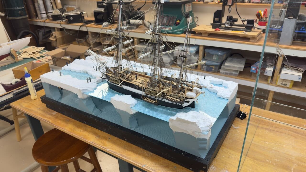
I love the presentation - besides the great job on the model, the diorama really brings your project to life!
I do have a question for you. In the background I see a Sherline lathe / mill combination; could you provide some insight on how you combined the machines?
Thanks,
Greg
-
12 minutes ago, clearway said:
I didn't alter the sternpost on my Terror but i did alter the stern on my Terror and Erebus so they could have the proper "stern tuck" - going off the fairing at the stern of your model i assume you are going down the same road.
Keith
Keith -
That's the plan! I'm also considering the possibility of a single layer of planking on the hull since I filled the spaces between bulkheads. I'll still need to plank over the plywood bulwarks - probably both outside and inside.
Greg
-
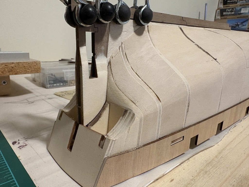
I've started to add the stem / cutwater / keel / stern assembly. This is not the time the instructions say to do so; however, I do have a rationale! The sternpost / screw trunk is basically the same thickness as the false keel, so near the stern, there should be some thinning of the false keel under the bearding line to the keel / stern so that planks can be set into a rabbet. Hence the reason I'm adding in the pieces now is so I can carve out some of the false keel and hopefully have the planks sitting nice in the aft region. Because of the way the bulkheads are formed a rabbet exists along a good part of the keel, but again there is no rabbit in the stem / cutwater region - but here things can be 'faked' a bit!
Here's the screw trunk / stern post being added - note, because I messed up the first kit, I had some extra parts available; here I've added the extra concave supports for the lower stern planking next to the false keel. This will let me plank this region in halves, but still have support on both sides of the planks.
When looking a picture of this region on Betts' model, I happened to notice that the doublers on this structure do not end at the same location fore and aft of the screw. So unlike the kit instructions, I tried to mimic Betts' work here.

-
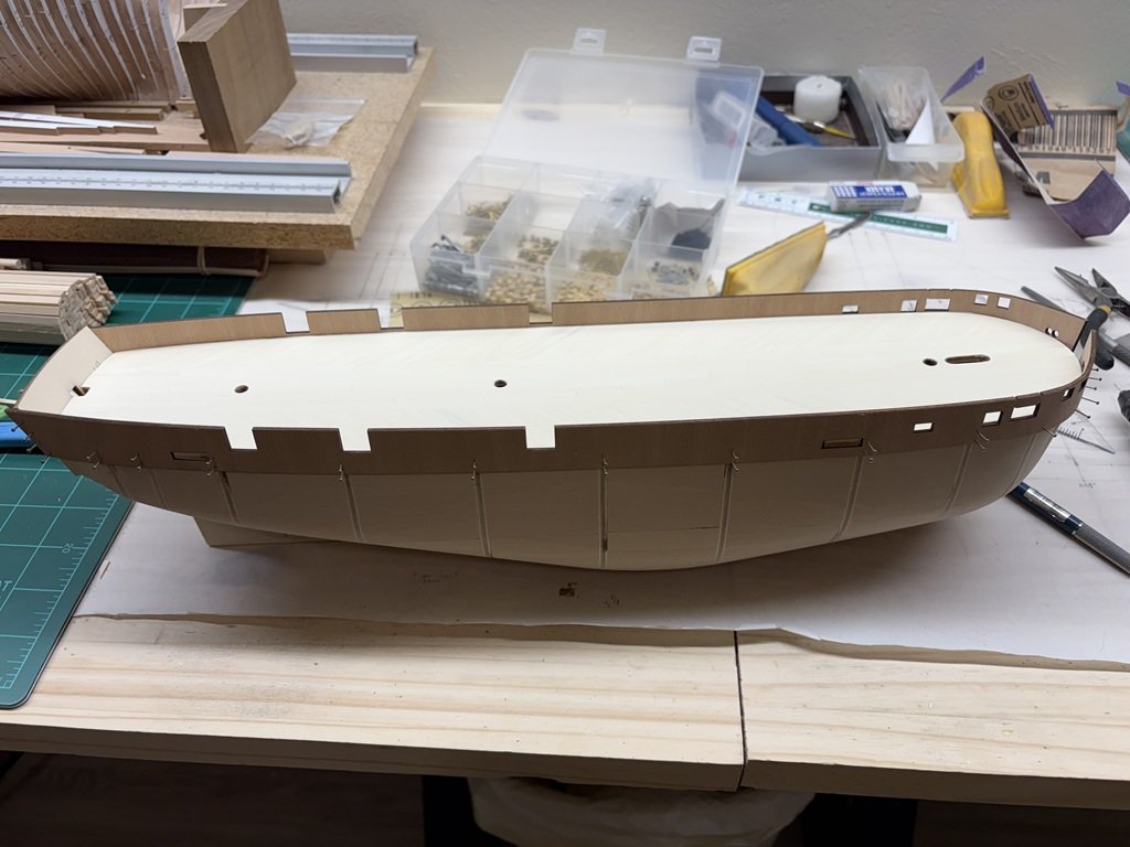
Started to attach the bulwarks today.
I guess I'm going to be a slacker here - from other forums, I knew that the kit bulwarks are not as high as those drawn in Betts' plans. I applaud those that have taken the time to raise them up and make other related adjustments! So this model is going to have bulwarks about 6 scale inches too short and the larger ports, within the bulwarks, are not being enlarged (which only works if the bulwarks are raised). If I change my mind later, the bulwarks could be extended during the planking process ...

HMS Terror by Greg Davis - OcCre - 1:75 scale
in - Kit build logs for subjects built from 1801 - 1850
Posted
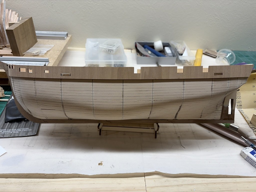
The port side planking is finally complete. It also got 15 min of smoothing before I decided it was too cold to sit outside any longer. But enough was done to get a look at what the hull is looking like now. Difficult (for me) to plank using the kit-supplied wood. A number of the planks would have been easier to fashion out of sheet wood / wider strips. There are a few 'gaps' that will need to be attended too, but all should be fine since the hull will be painted. Nevertheless, it has been a 'fun' experiment. Hopefully the starboard side will go quicker - or at least more easily! After the whole hull is planked, I'll do the rest of the sanding and get on to the ice channels. I don't foresee the need to do a second planking.
Not sure when the next update will be as I think I'll be giving additional attention to a few other projects.