


Greg Davis
-
Posts
350 -
Joined
-
Last visited
Content Type
Profiles
Forums
Gallery
Events
Posts posted by Greg Davis
-
-
Frame 30 is going well - just two top timbers to attach and it will be complete.
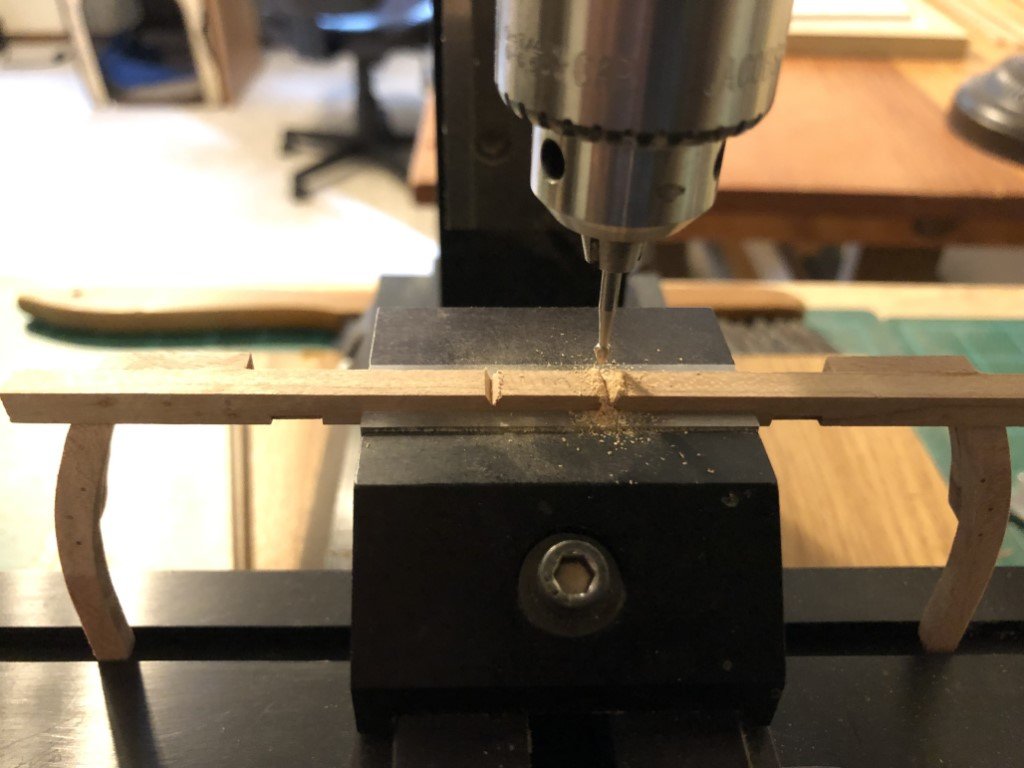
While some glue was drying on frame 30, I drilled holes for the 168 fasteners in the main carlings
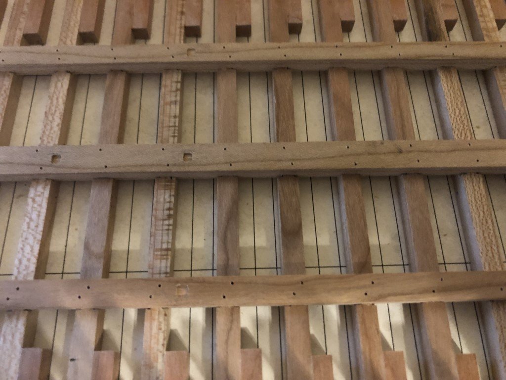
I am wondering how many (thousands?) of fasteners there will be in this model. Once these carlings are done, I believe the count will be 796 - good thing I ordered more #74 drill bits!
- mtaylor, GrandpaPhil, druxey and 5 others
-
 8
8
-
The bow frame together with the associated supporting knee have been completed. Here they are set in position:
Hopefully, frame 30 goes a bit more quickly based on what I learned assembling frame 1!
The frames will need a small amount of fairing and I wonder if it may be best to work inside first. If I work in this order, then I can place the interior side strakes that tie to the curved portions on frames 1 and 30 via four knees. This would then stabilize the structure in all three dimensions. Afterward the exterior of the frames can then be faired. This order would be reverse of the prototype model displayed in Delacroix's manuscript where exterior planking preceded interior work. Pro's or Con's?
- bruce d, GrandpaPhil, mtaylor and 6 others
-
9
-
Frame number 1 turned out to be the choice. After a couple of false starts, it is coming together now! Now will wait for final adjustments until tomorrow as the epoxied joints between the uprights and the floor dry over-night.
- ccoyle, GrandpaPhil, druxey and 3 others
-
6
-
The frames are all glued to the carlings (minus #1 and #30). While the joints dry over night I will be weighing pros and cons in choosing between three tasks to be the next step in constuction:
- Complete frames 1 and 30 which will form the bow and stern
- Drill and insert copper wire 'bolts' through the three main carlings into frames #2 - 28
- Begin to form the two (curved) carlings that will fit in the angle made by the bottom timbers and the knee / top timbers
- GrandpaPhil, mtaylor, bruce d and 2 others
-
5
-
Everyone - thank you so much for the encouragement!
This evening I have begun to attach frames to the carlings with a bit of yellow glue. I'm looking forward to being able to pick up and look at the structure from different angles.
Greg
- mtaylor, Keith Black, Roger Pellett and 3 others
-
6
-
I've milled mortises into frames 2 and 29 for the bitts as well as a number of mortises in the carlings for posts that will support the deck structure. A half dozen slots have also been cut into the ends of the carlings where top timbers associated with the bow and stern will pass.
I believe that I have completed all work needed prior to permanently attaching the carlings and frames (with the exception of frames 1 and 30 that will be dealt with later).
- Keith Black, bruce d, Bitao and 5 others
-
8
-
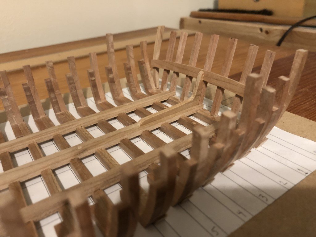
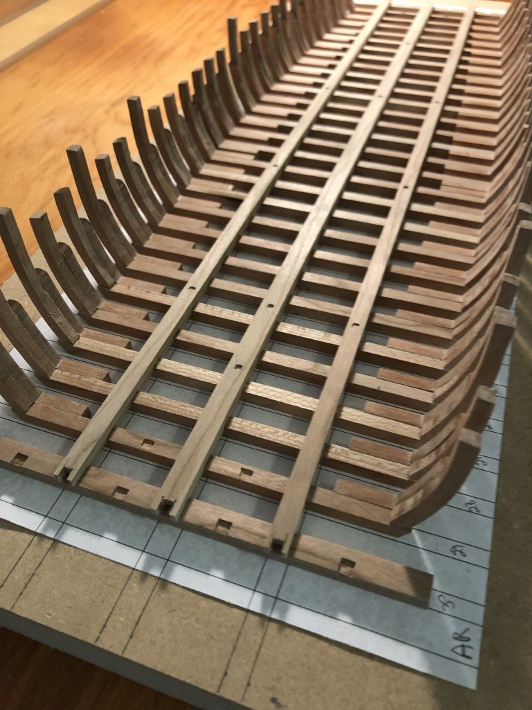
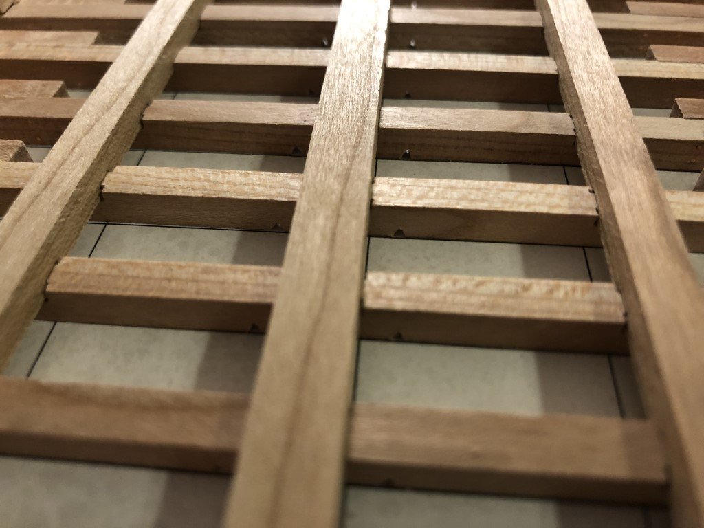
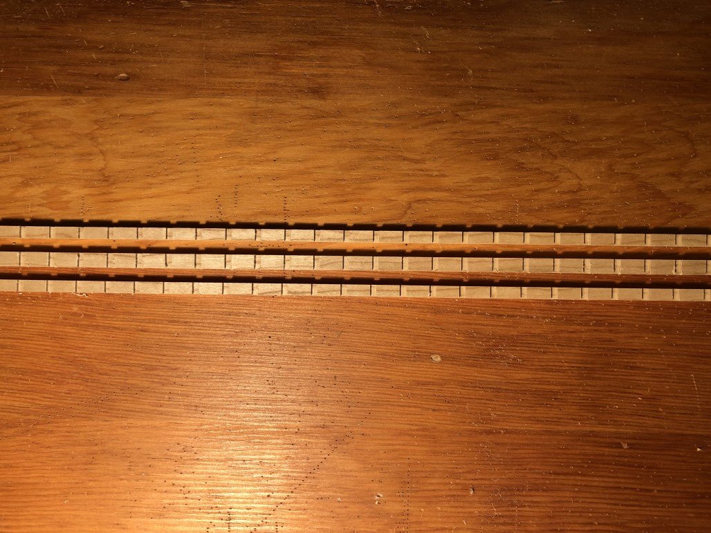
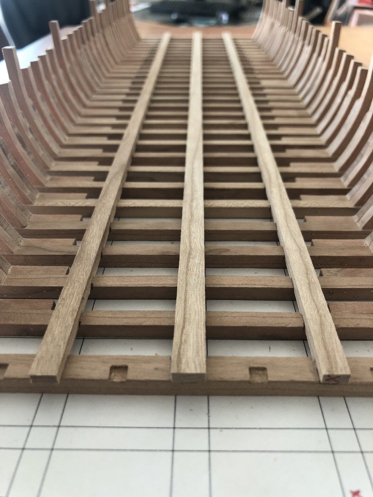
Today notches for the limber channels were milled into the 28 interior frames. The notches are equilateral triangles with height 1.25mm.
After placing the frames back in their proper positions within the main carlings, the limber channel is visible
- Seventynet, GrandpaPhil, mtaylor and 7 others
-
10
-
Thank you very much!
- Keith Black and mtaylor
-
2
-
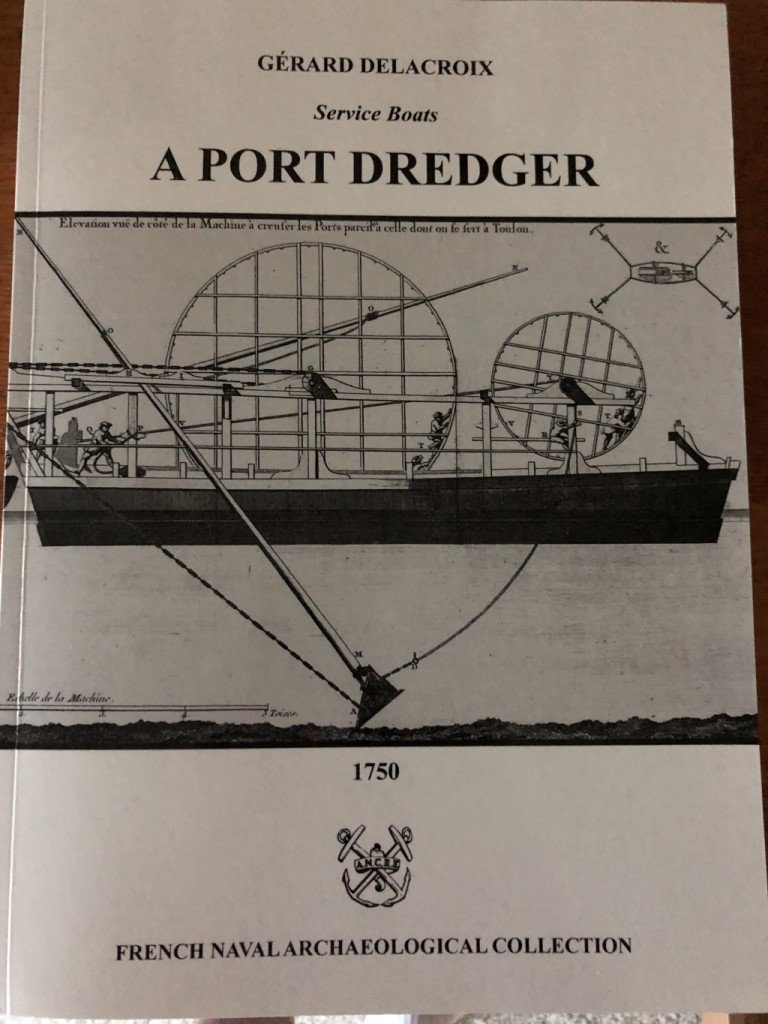
I have chosen to build a model of 'A Port Dredger' following the Ancre monograph by Gerard Delacroix:
It does not appear to be a common project, although there is a wonderful build log on MSW:
- Machine a curer les ports 1750 by guraus (Alexandru) - 1/36 - Finished
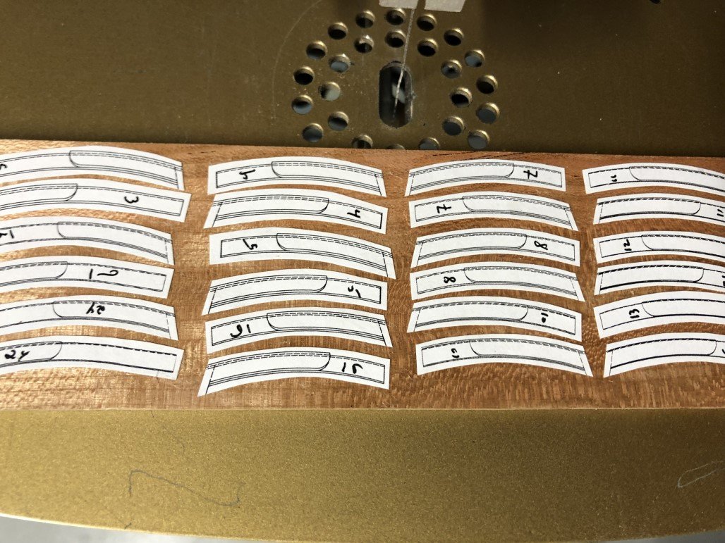
I have chosen cherry as the wood species for the model. I was given a piece of this species of wood by a friend a number of years ago and it is being used for the frames and main carlings. Unfortunately, the piece will not be enough to complete the project, but fortunately I was able to source additional matching cherry locally. All of the wood is rough cut so I will be milling everything I need for the model.
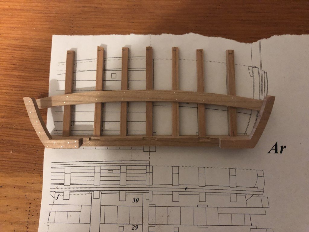
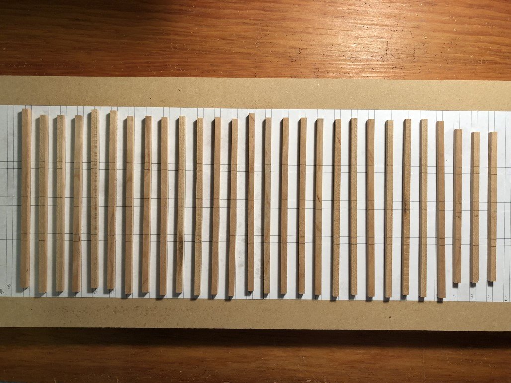
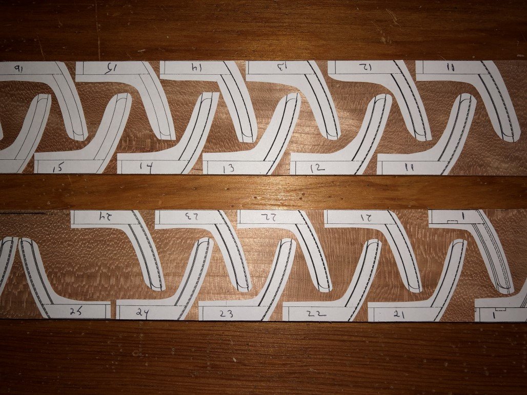
I began by making the three main carlings and 28 of the 30 floors:
The floors were cut overlength and marked for 6 notches each that will match with the carlings.
The notches were fashioned with a chisel, unlike the notches in the carlings which were milled.
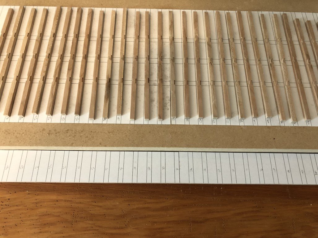
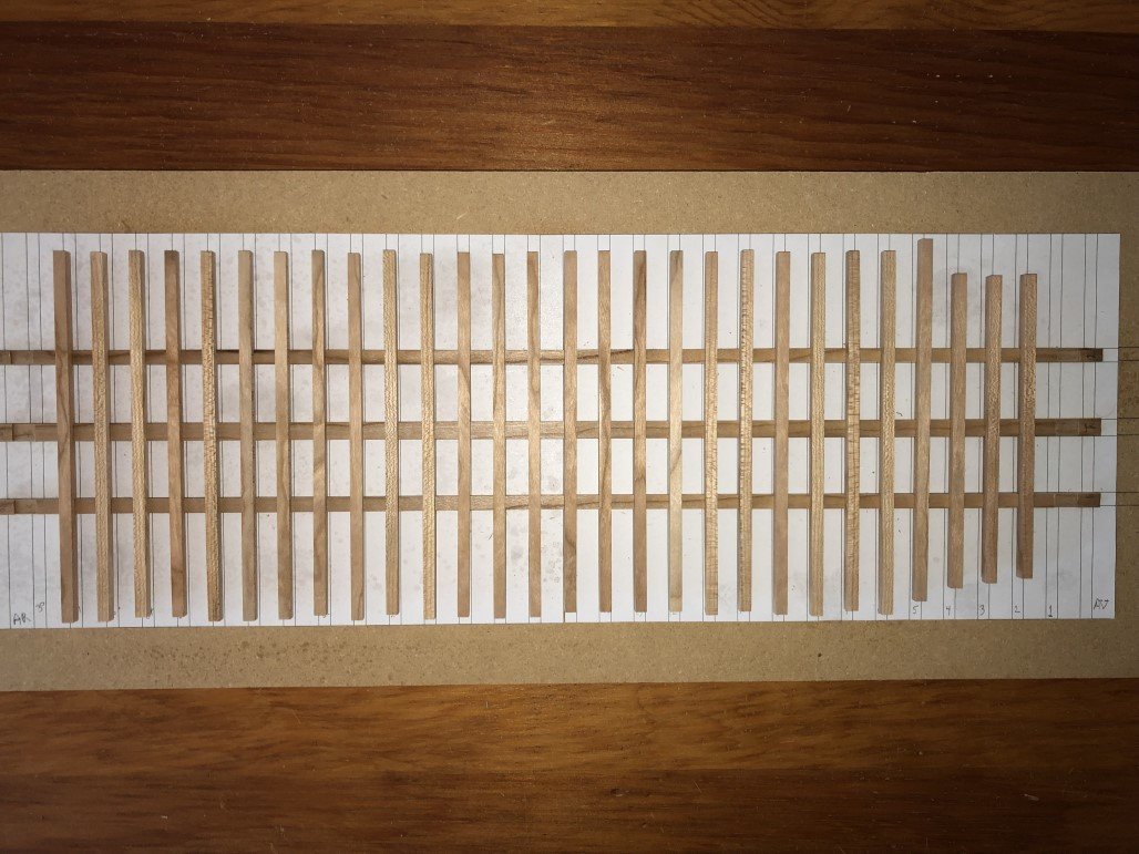
The floors and carlings nicely mate!
Next knees and top timbers where cut out with a scroll saw.
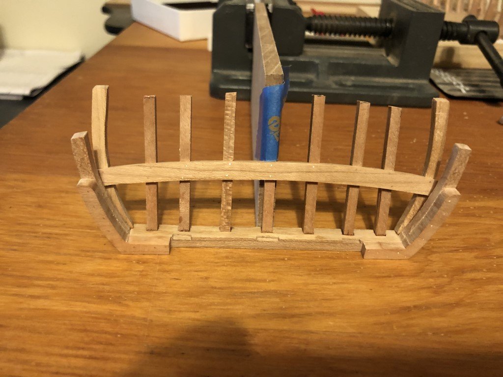
The knees where positioned and glued to the floors. At this point, the hull was starting to take form (here the frames and carlings are not permanently connected).
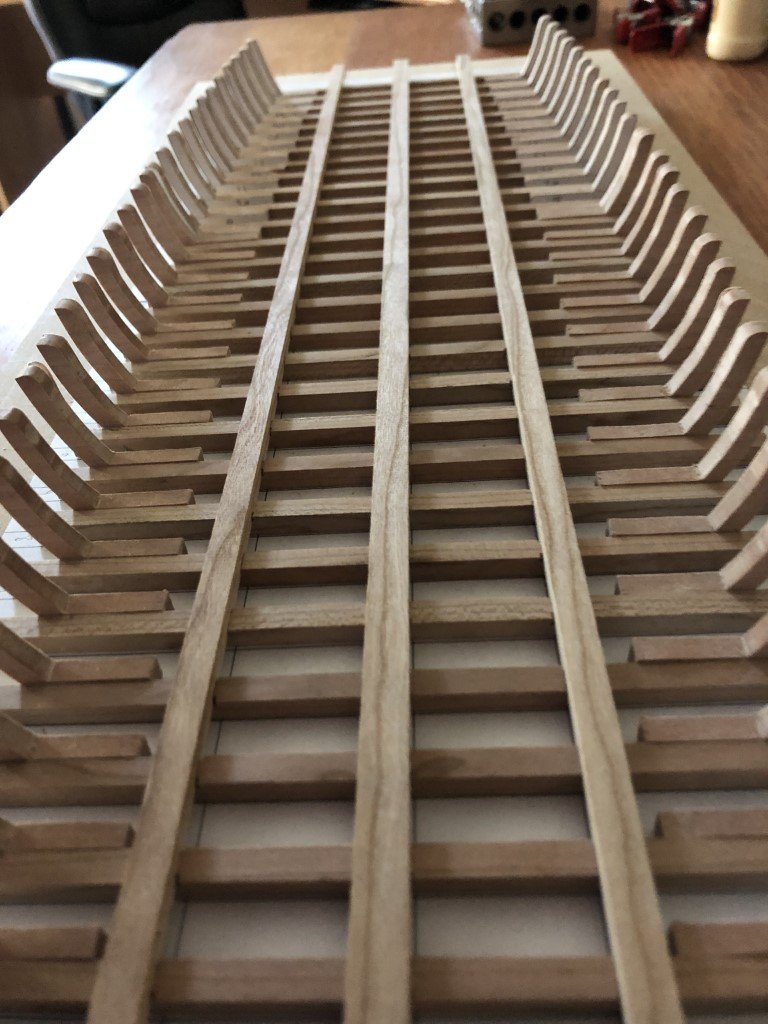
After a bit of final adjustment on the knees to be completely level with the floors, the top timbers were added.
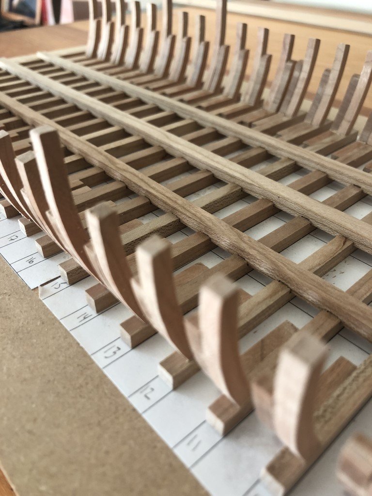
Each frame / knee/ top timber combination was then drilled for 10 'bolts'. The holes are 0.5mm and the 'bolts' are 24 GA copper wire. It did take me 3 #74 drill bits to do the job as I did break 2 of them. After inserting the copper wire with a touch of CA glue, followed with a bit of filing and finish sanding got the job done. I am satisfied that the 'bolts' are visible but don't overly direct my eyes to them.
- James G, Keith Black, druxey and 10 others
-
13
-
In fact, for other following Frank's build (and Yves' comment) - here is a link to where he found the building jig idea for Emma: https://www.historicshipmodels.com/emma-c-berry/ .
Greg
-
Frank -
I'm glad to see you have started your build log and am pleased that the building jig is helping you along!
Greg
-
First, I would like to commend Andrew on his fine rendition of Emma C. Berry! Andrew, I have visited your forum many times over the past year to view your progress and see how you have navigated the build.
I would like to offer clarification on the jig I made use of. I have had this kit on my shelf for years and had always worried about working with the fragile frames that form the hull. Eventually I built up the courage to put this kit together. Having studied how POF models are scratch-built, I felt that a commonly used jig could be developed to up my chances of successfully building Emma. Since the jig wasn't my end goal I did not make the perfect one and instead went for more of an ad hoc solution.
Marking the centerline and the perpendicular location of each frame was done precisely on both the jig and the building board. The holes for the bolts were drilled before this was done so that the alignment would be consistent. The kit plans were used to make a rough outline for the jig and was cut out. Slots for the frames were cut oversize as all of you have noticed. The jig was set at a convenient height so it would intersect with all of the frames.
After gluing the pairs of pieces to make each full frame together, I did attach a strip across the top to keep proper width. The centerline was also noted on the top of this strip. When each frame was glued to the keel I was able to center the frame using a thread going fore-aft along the center line - and as noted in an above post, by measuring the height of each side of the frame above the jig. Strips of wood were then glued to the frame to restrict the frames from expanding outward and to maintain their proper position.
Once the full frames were in place, I was able to remove all of the temporary strips that had been attached prior to the erection of the frames. The jig held the frames nicely so that I could fair the inside of the frames near the keelson location. The keelson was added as well as the half-frames and then the rest of the interior fairing was done.
Again as noted above, the jig made clamp installation straightforward with little worry about damaging a frame.
I will say that if I were to start over, I would install most (or all) of the ceiling before installing any deck beams etc. I think it may have been better to put in the well bedlogs and did some work on the cabin and platforms before installing the ceiling. Then I would put in the wet well and so on. I guess you learn something every time.
So thanks to all of you for taking the time look at my work; and Andrew - congratulations again!

A Port Dredger 1750 by Greg Davis - FINISHED - Scale 1:36
in - Build logs for subjects built 1501 - 1750
Posted
I now have all 30 frames finished!
Today, I was also able to install and then smooth the fasteners through the carlings into the frames.
Helped along by Druxey's comment, I have decided to work inside first. The three other builds of this vessel that I have been able to study (Alexandru/guraus's MSW build log, gipsy's build log on the Marine Modelisme d'Arsenal site, and the Rimlinger model in Delacroix's manuscript) do not appear to use any supporting mechanism during the fairing process. I did start to sand the interior a bit but soon became concerned about robustness of the frames and convinced myself that I would feel more confident with a supporting frame. So, over the next few days I plan to construct an exterior frame based on the hull's envelope to support the current structure during the interior fairing process.