


Greg Davis
-
Posts
712 -
Joined
-
Last visited
Content Type
Profiles
Forums
Gallery
Events
Posts posted by Greg Davis
-
-
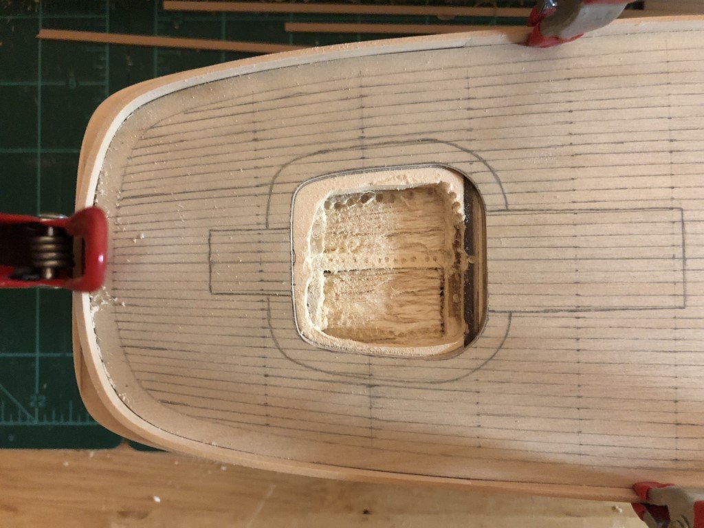
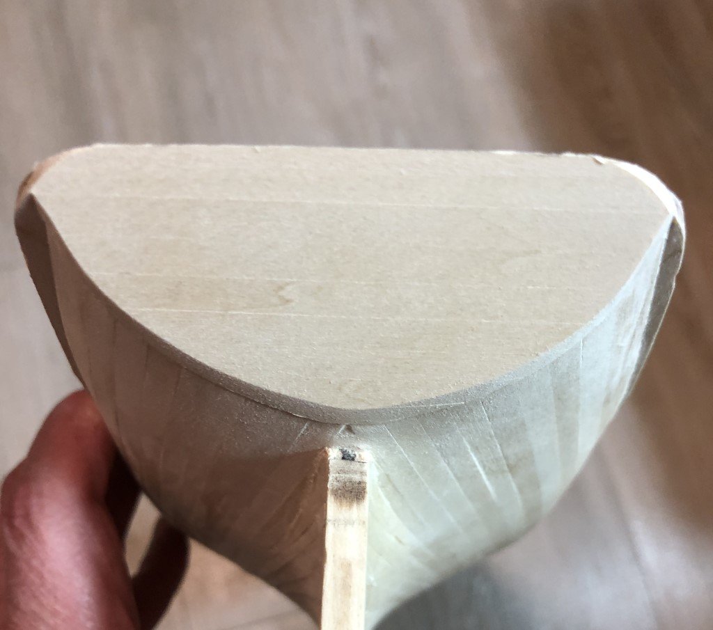
I'll keep my eyes open for additional information about the grating, in the meantime I now have created the right amount of space for the cockpit to drop under deck level. It looks like a mess, but it will provide a stable base for the ensuing work.
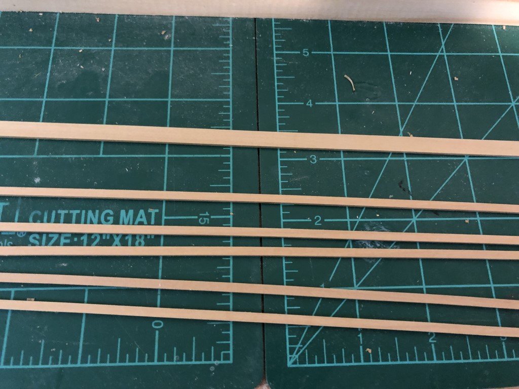
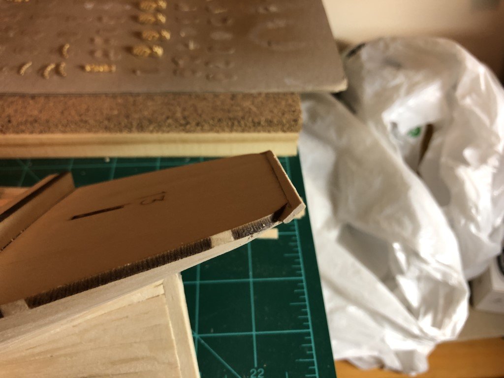
Here's the material I plan on making the cockpit walls from:
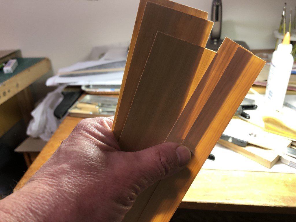
This 1/3 mm Costello Boxwood - its pretty thin; a lot of light shines through the sheets. I had made this for another modeling project (Santos Dumont #18 Hydroplane) and have a lot of extra, so I don't need to make more for this model. I'll be using 3 layers to build up the walls. The kit came with a mold for the wall to be 1/4". I will need to make a new mold so that I can form some material to a height of 1/2" to accommodate the depressed cockpit floor.
-
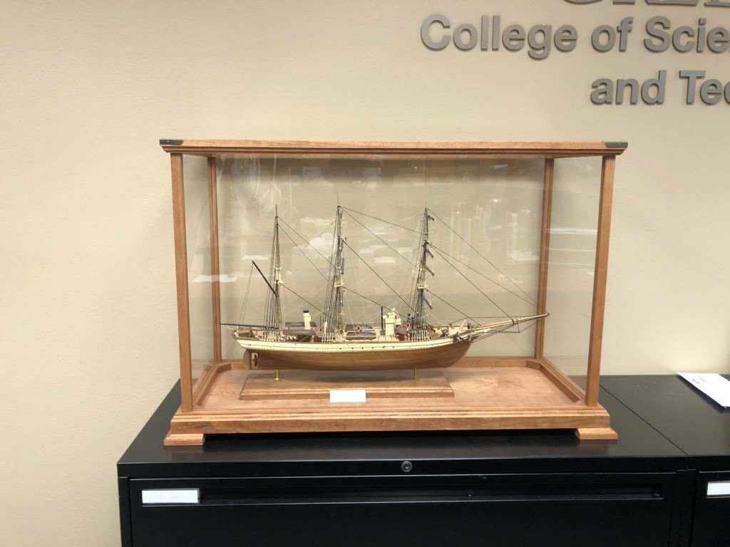
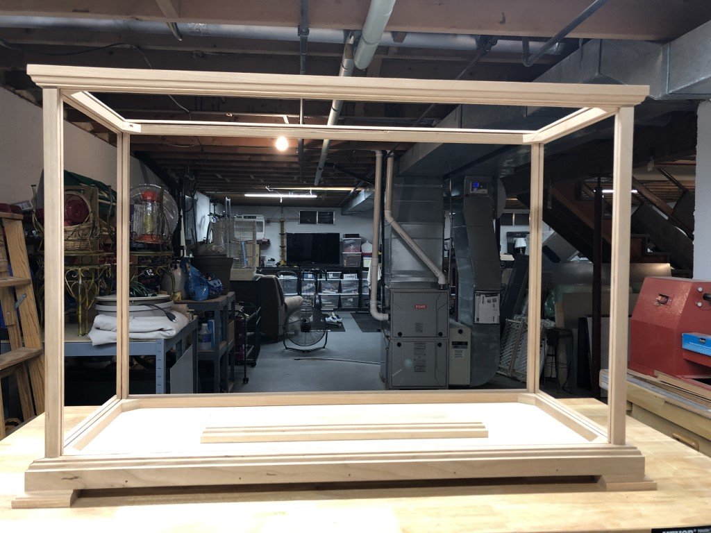
Here is the final product - case and all!
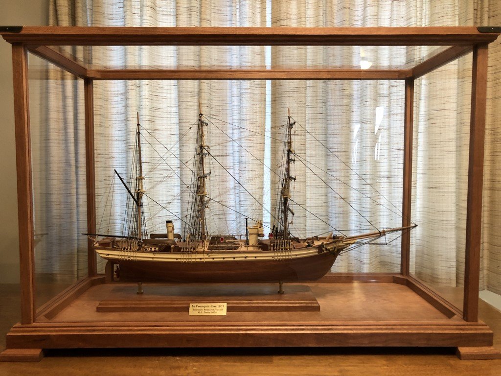
After a successful trip, the model now resides in the Dean's Suite for the College of Science, Engineering, and Technology at the University of Wisconsin - Green Bay.
-
8 hours ago, juhu said:
Thank you for the reference to scratch built Phantom, must go through it. The attached book picture brings to me one technical question. What was actually the purpose of that grating? I believed it was to drain the water out of the cockpit. But in that case it should be in cockpit floor level. But I might be wrong here, may be there was some special scupper for that? I believe there must be some way to get water out. But for sure the grating in the picture with noticeable step above the cockpit deck in quite a cramped space opens for me the question, what was it good for?
I had been thinking about this as well. I don't know the details of the actual construction of a cockpit in such a vessel. My guess is that the grating allowed one to stand above most of the water that made it into the cockpit area, a region that would be less slippery than the deck itself. Also, it would help keep the person from standing in water whenever there was some - so a bit dryer. But, as you note, there would need to be a way for the water to leave - otherwise, it would end up in the cabin. I have two guesses on how that may have been done - one is that there could be drainage pipes on each side of the cabin opening (due to the direction of deck slope) that led to scuppers, the other is that there could be drainage pipes to limber and then the water was pumped back out of the ship. The former seems like a better idea to me because the drainage would be passive, whereas the latter requires crew work.
It would be great if someone that knew the actual answer could share!
-
13 hours ago, juhu said:
Difficult part of the build, at least it would be for me. Not sure of cockpit construction, was there supposed to be grating at the bottom, at least aft ? Could be a challange to do it now, after hull is planked and false deck ready too. I guess you plan to make a hole wide an deep enough, then make full cockpit, glue it to the reverse side od the false deck and only then put it atop together?
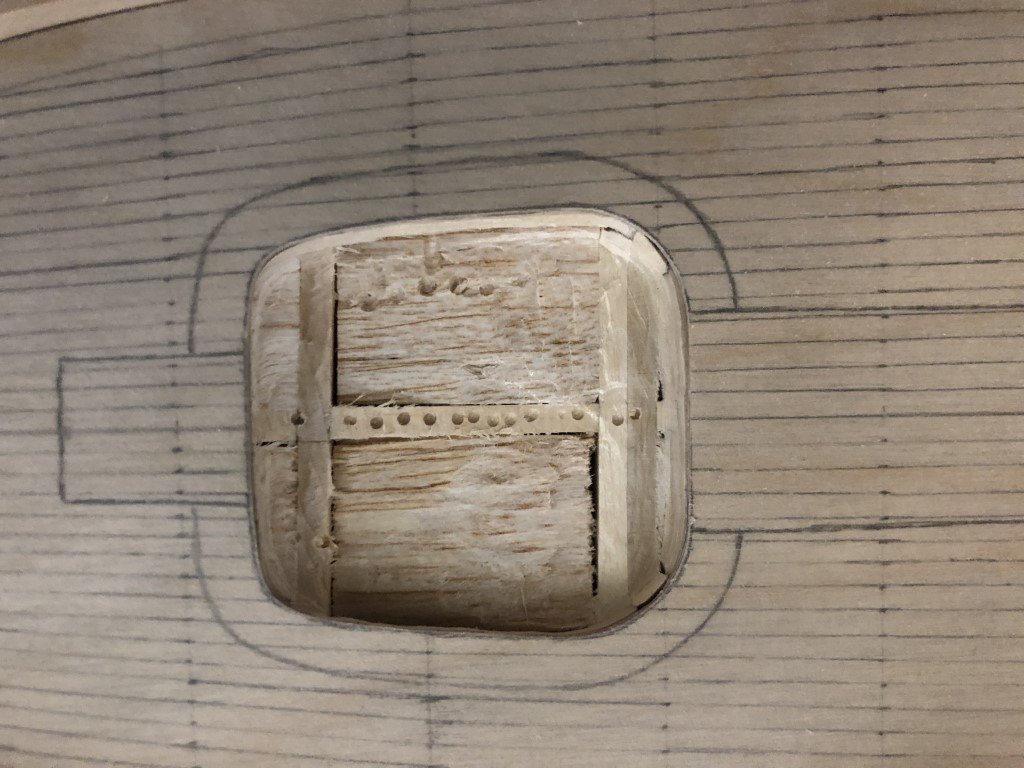
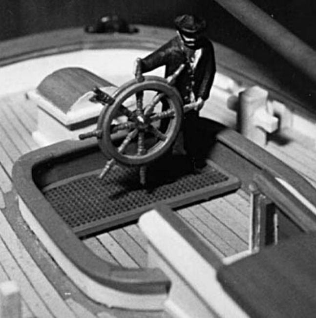
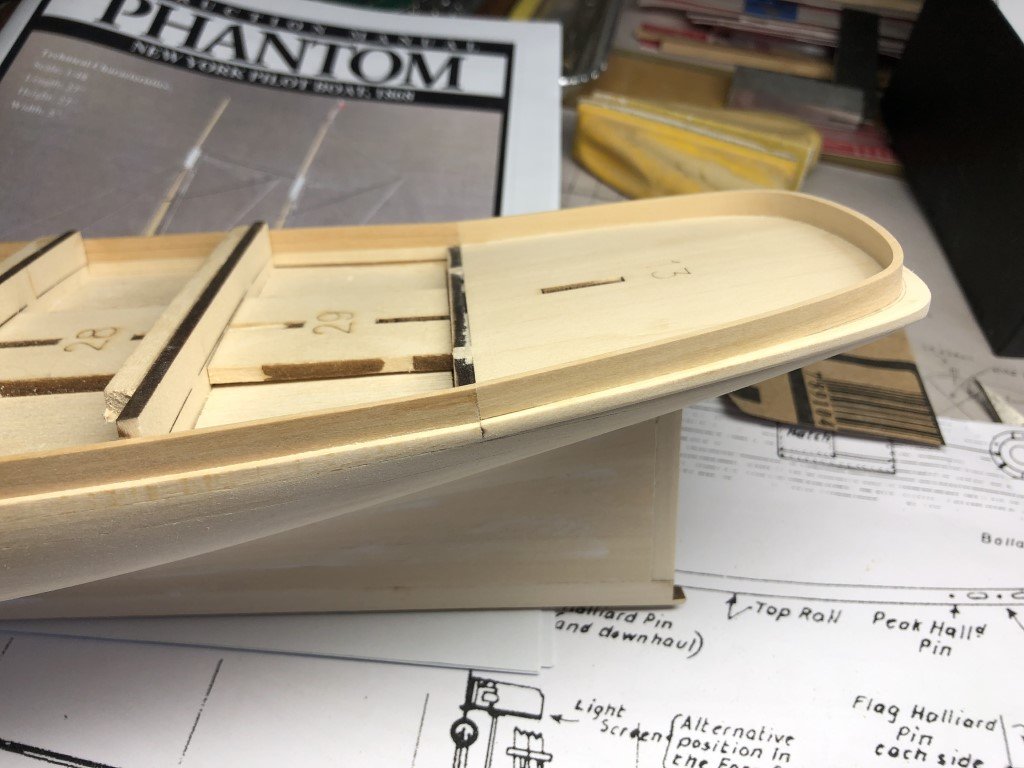
Yes, I currently plan to build most of the cockpit outside of the model and then drop the structure into place. A piece of thin plywood will be made to support the planking that will be done prior to placing it in position. The cockpit bulwarks will go in next, followed by the deck level planking. I'll set some grating on top of the cockpit floor afterwards. I am very much following the work described in the Volk, Davies-Garner book. This is a picture from the book showing their version of the cockpit and grating:
Victory 78's scratch build of Phantom on this forum, is closely following the book and as the hull was made, there was space made right away for the cockpit (and other below deck features). I hope Victory 78 starts posting again soon - the work is so nice!
-
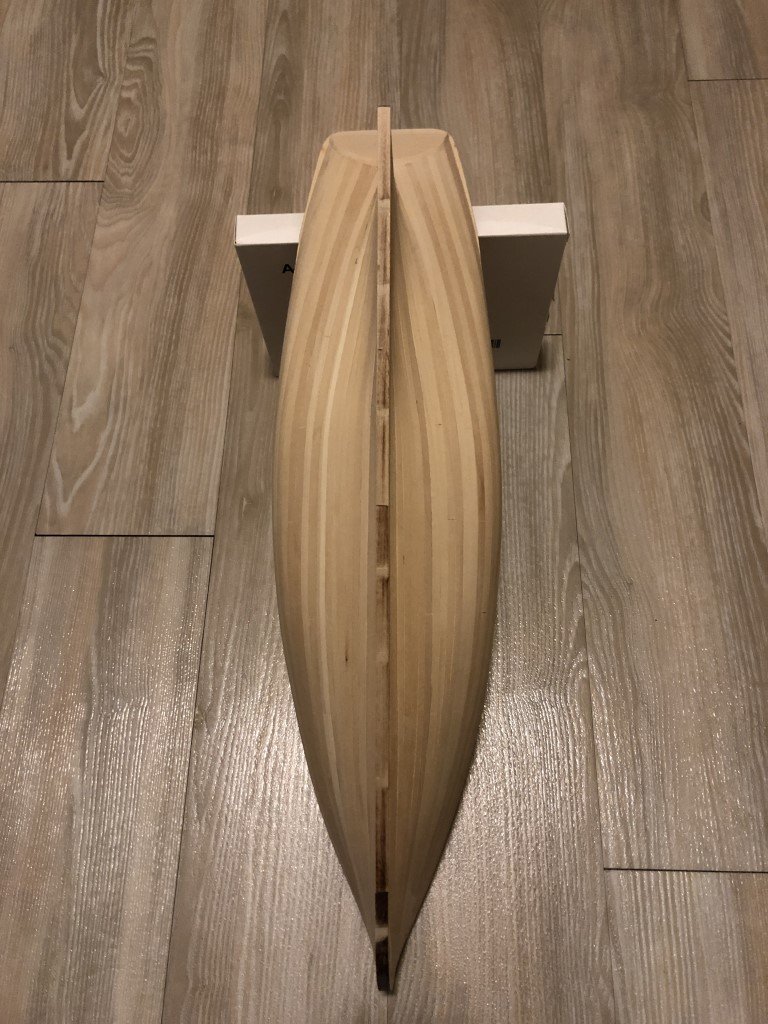
Well, I'm really going for it - cockpit surgery has begun! I'm going down 1/4" so that the cockpit floor will be the accepted 1 scale foot lower than the deck. The cockpit floor will have a good attachment - besides the center piece of wood, the front of the cockpit will sit over bulkhead 8 and the rear will sit on bulkhead #9. This should make installation reasonably straightforward. The milling is being done with the deck pattern removed - the cockpit shape has been traced on the stern deck wood and a small piece of wood that I need to attach for of bulkhead #8. I'm using a Dremel cutting bit to work toward the edges. I should have better planned ahead and did this before the hull was planked. At that time, I could have secured the hull on my mill and more easily milled out the space. To late now - still should have a good outcome!
-
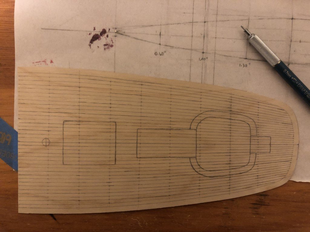
The aft deck template shown a couple of posts ago was actually made on 1/64" plywood - not 1/16" as I typed. After placing it in position on the model and pressing down between the bulkheads I decided that the material was too thin / flexible for its purpose. So here is a new template made from 1/32" plywood. It appears to have the right amount of stiffness yet allows for bending in all necessary directions along the deck profile. Liking this template more, I went ahead and drew in the planking scheme. I should probably mark the timberhead locations on the waterway and then notch them out - the result may be better than gluing them on top of the waterway. (Probably over-doing it - scale back, scale back - the model will probably never leave the house!)
The maximum plank width is 1/8"; i.e., 6 scale inches and this conforms well with the plans and information in Chapelle's books 'The American Fishing Schooners 1825-1935' and 'Boat Building'.
I am planning on milling the planking material to a thickness of 1mm - just a bit more than 1/16". So once planked and smoothed, the finished decking will be 1/16" or slightly less. Today I'm thinking about trying maple for the planks and swiss pear for the margin plank and timberheads.
- cotrecerf, catopower, Thukydides and 2 others
-
 5
5
-
14 hours ago, juhu said:
Hi,
I was also scanning the pic from #46 post, not sure first what was meant, but I think the idea was that the size/shape is way off? I mean the copy of the plan, particularly in the aft part does not match the hull / transom / deck at all and is too short? If this is the case, that is pretty bad.
As far as deck planking is concerned, very good point comes from #48 - would the cap rail fix the missing height? If yes, great, if not I would suggest to try to use less thick planks. Something like 1/2 or even smaller of the suggested strength with careful sanding then might do the job and even make deck planking easier. At least from my last build it helped me a lot. The other option would be to raise the bulwarks as you mentioned. Not sure how much it would hinder the hull appearance, but considering the shown mismatch and distortion compared to plans, the question is if it matters anymore... I mean, is it possible to build scale replica from this kit? I have it in my shopping cart already, order and delivery to Europe is by no means cheap, but am more and more reluctant and not sure if I will commit the purchase.... It seems to be like with plastic kits: while downscaling a kit is relatively(!) easy, you are omitting details, upscaling must not only consider additional details but also their effect on the proportions and build overall. I have several ME kits in my stash, they are beautiful, looking forward to building them, this new Phantom seems to me well, like some different approach. Will keep an eye on progress and wish all the best with it.
Edit: One more question I forgot. From few pics on the web it seems to me that this ship also has the stepped up deck, i.e. thick beam (called grub beam?) divided main deck and quarter deck? If so, I wonder that there is actually no corresponding rail step, meaning that the rail height must be lower at quarter deck than at the main deck? But as said, this might be just my misunderstanding of the given ship design, I have never build smaller Phantom.
Thinner planks are certainly an option - I think I may get away with 1/32" planks. As you note, not much room is left for error / sanding! But if I use a subdeck, smoothness of the initial planking job should be reasonably good.
As for the overall accuracy of the model when completed - I think a very nice model will be the result, one that will be great to display, and one that is certainly a good value for the investment (both material and time spent).
Will it be a perfect replica? - probably not, but this is most often the case with models, especially those from kits. My disappointment is in the discrepancies between the plans and the kit pieces. Quite frankly, I have no good idea if the plans themselves are truly accurate and I don't think there is any way to proof-check them. I believe that right now, I'm doing something I shouldn't be doing - being overly concerned with each and every deviation. I should be reserving these feelings for a 1:48 scale frame model built to ANCRE plans or similar and being made for competition and/or a wealthy client (wish I had one of those!).
Its like many Model Expo kits - a really good starting point, with lots of potential, and a good deal of room for frustration because the kit could be so much more for not much more thought and / or production cost.
Yes, the ship has a stepped deck, so issues to address up front as well!
-
15 hours ago, Dr PR said:
What was the surprise in post #46? Something to do with the mast but you didn't say what.
In post #47 are you allowing for the thickness of the cap rail on the bulwarks for determining bulwark height above the deck planking. If the cap rail is also 1/16 inch thick will the height be correct above the 1/16 inch deck planks?
From your photos it looks as if part 13 (the subdeck at the stern) is cocked up at a pretty sharp angle.
I am also concerned about the transition between the subdeck and the rest of the ship. Fortunately, it is not quite as extreme as the photograph seems to indicate. I've already gone after the region with a good deal of smoothing to help with the transition. I am considering the plywood deck underlayment partially because it will additionally smooth out some of the junction angle. I might need to add a small amount of material to the top of the bulwark to have a nicer flow.
-
With respect to the bulwarks, I've made a sketch to better explain the situation.
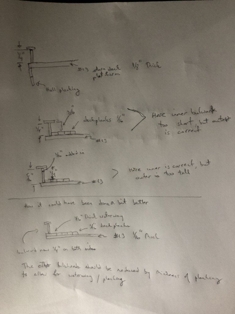
According to the plans, the bulwark height - distance from planking to under the rail - should be a constant 1/4" along the aft deck. This measurement is for both the inner and out bulwark . Before planking the aft section this is how the measurements are. If the aft deck is planked with 1/16" material the outer bulwark dimension remains 1/4" but the inner becomes 3/16" and is shorter than it should be. If 1/16" of material is then added to the current bulwark, the inside dimension is corrected, but the exterior dimension becomes too large by 1/16".
There are ways to correct this - but it would take more work than I care to do at this point. In the aft portion of the vessel, if part #13 had been made 1/16" thick, then a 1/16" piece could have been used as a waterway and the bulwark planking could have been positioned over it. This would also have required that the remaining bulkheads had been made 1/16" lower to accommodate the planking and waterway.
I think this would have been a good place to have used laser-cut parts in the kit. The waterway could have been laser cut with locations for timberheads precut.
Due to how the kit was manufactured, the distance between the fore deck and the rails will also be too small. According to the plans, the distance between the deck planking and the bottom of the rail should be 7/16". The way the kit is constructed the distance is 3/8" before planking - this will be reduced to 5/16" after planking with 1/16" material. Down the road there may be some issues due to the missing 1/8" - I am most concerned about what this will mean for locating the hawse holes.
-
The surprise in #46 is that the deck plan didn't match the deck length by quite a bit - 5/16" in fact.
I now realize that a portion of that discrepancy is my own fault - when I planked the transom, the deck length was extended by 1/16". The remaining differential of ~1/4" is a miss between the model and the plans. I was rereading the Volk / Davies-Garner book 'Working techniques for model shipbuilding" and the discrepancy is noted there as well; in fact, it is a discrepancy from the original 1/96 plans that remains after enlargement to 1/48 scale.
I made template of the aft deck using 1/16" plywood and have repositioned the deck plan slightly.
The mast hole is over the slot in the framing. The space between the mast and skylight was increased by 1/8" and the space between the skylight and deckhouse / cockpit by 3/16". I couldn't move the cockpit / rudder house back any further without having a severe mismatch in location with the rudder post. At the end of the day, it will look OK as the proportions have not changed drastically.
I've marked a 3/16" waterway on the template and will probably line off the planking as well. I am considering planking directly on this template and fastening it to the model as opposed to gluing the planking only to the bulkheads in the front portion of this deck.
-
I think I've discovered another 'issue'. This one is a bit more serious and I don't have a good solution.
In relationship with the bulwark planking, the top of the bulkheads and part #13, the stern deck underlayment, are already at deck level. That is, no space was engineered into the model for the thickness of the deck planks.
Now if the deck is planked with 1/16" material as called for, the inner sides of the bulwarks will be short by that distance. If the bulwarks are then extended, they will be too high on the exterior of the model.
The deck profile / height at center and side are clearly marked on the kit plans (drawn by Campbell), but apparently were not conformed to in production of the model.
Ideas? Any would be welcome!
-
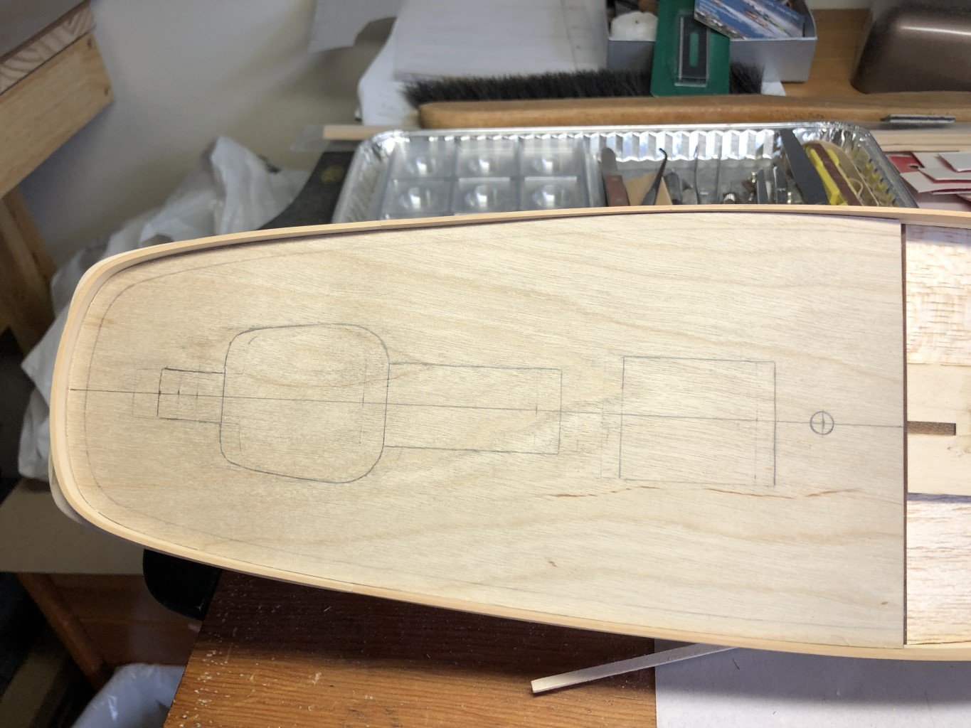
Popped off the bulwark molds, smoothed out the bulkhead tops along the quarterdeck. I then made a copy of the deck plan provided with the kit. I cut it out to place on the deck to help position the cockpit and other features on this part of the boat. I matched up the mast location and big surprise:
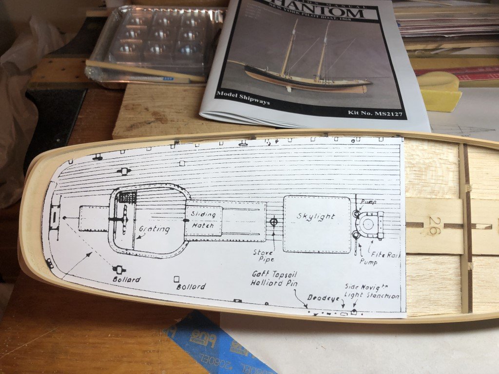
Quite a plan / model mismatch! Looks like the 'plans' are going to be a 'guide'. Not insurmountable, but not a good look for Model Expo's new offering - another missed opportunity for a good check before kit release.
- JacquesCousteau, ccoyle, catopower and 2 others
-
5
-
The case has been stained and given a coat of polyurethane. Here's port and starboard views of the model in the case:
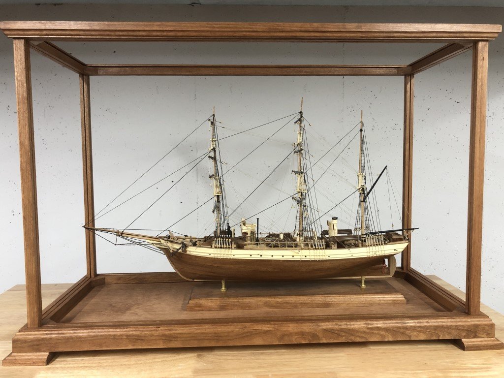
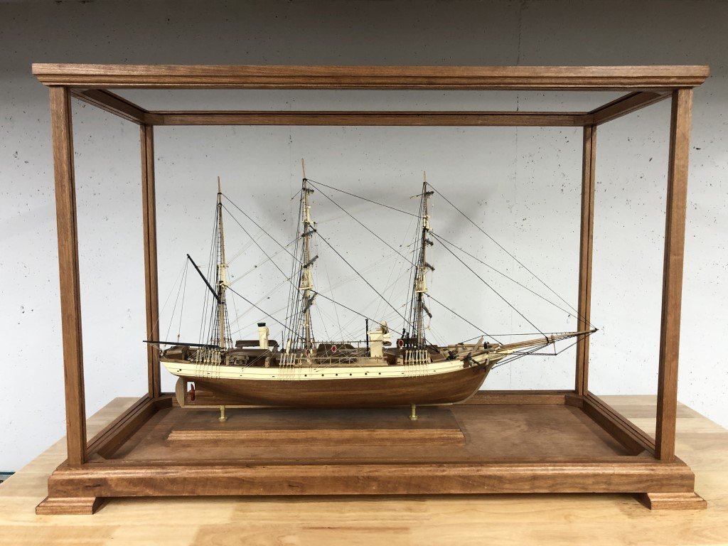
A few more steps - fasten the display board to the base board, cut and install the clear acrylic panels, and attach some felt to the feet of the case - then I can make delivery of the project. Completion is coming into view!
-
The aft portion of the bulwark attachment went well!
I think I will now work on the deck for a while. It is either the deck or painting / coppering the hull. I have the feeling that I have a better chance of messing up the hull when working on the deck than messing up the deck when working on the hull!
-
The mid / forward portions of the bulwarks have been installed successfully - this is the part that used two 1/8" high strips of the c. boxwood.
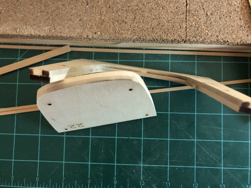
The aft portion made from the 1/4" strip came out of the mold nicely (with no char marks)
I need to now remove the bulkhead extensions (or at least the last one) so that this piece can be trimmed and mated to fit the rest of the bulwark.
-
9 hours ago, hamilton said:
Just catching up on your build, Greg - was that Corel's La Couronne behind Phantom? She looks nice too!! You are sorely tempting me (and my pocketbook) with this build....
hamilton
Yes it is the Corel kit. I've been picking away at it over the summer / fall. I started it quite along time ago and just let it sit. Now I would like to finish it - I am looking forward to the rigging aspect of the model.
Greg
-
Quick update! Successfully got the C Boxwood to conform to the mold. Tomorrow the result can be seen - hoping for the best!
-
Working on the bulwarks yesterday and today. I have the first strakes of the thinner material attached. It went on quite well - one strake to go.
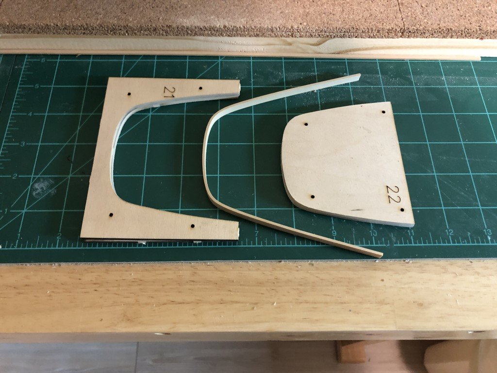
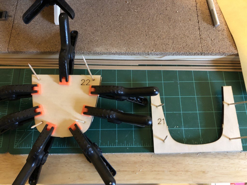
While letting the above work dry, I released the four pieces of material that are to form a mold for the stern bulwark. I was a bit disappointed as I worked on the mold. In each pair of pieces for the mold, there are four registration holes to align the pieces while gluing them together. Unfortunately, the registration holes do not nicely match. I eventually found the best matches that I could by flipping / stacking the pieces. Even then, the holes for the alignment toothpicks is not great - only good enough to sort of get the points in. Thus in this picture you can see the toothpicks pointing in various directions:
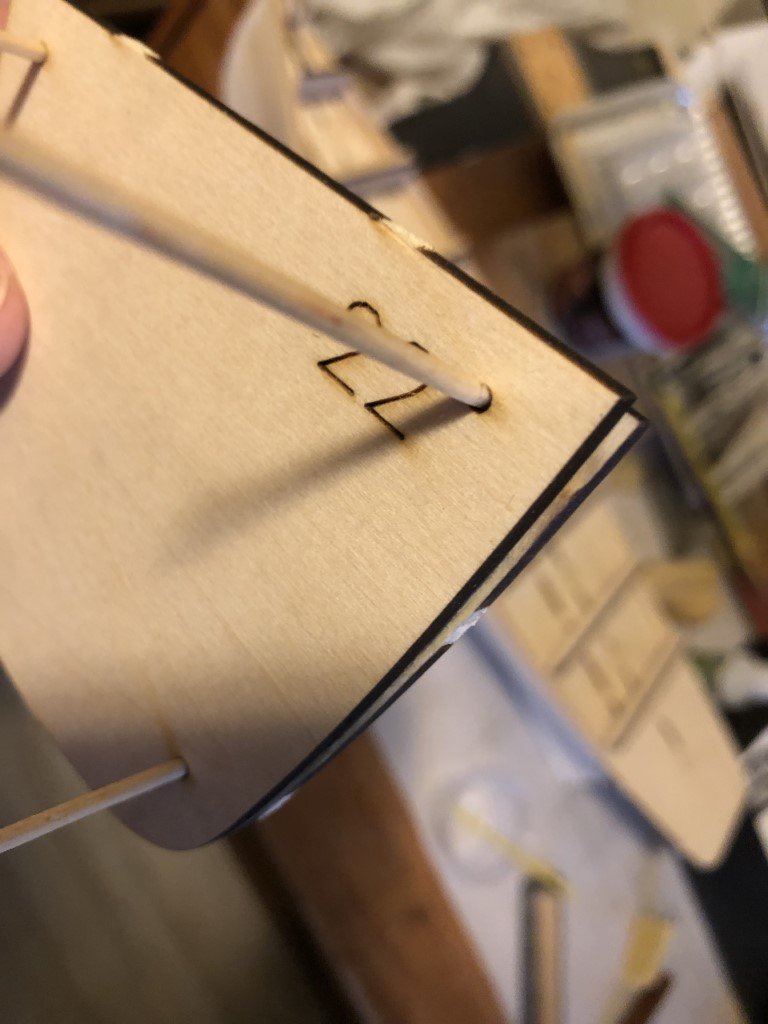
The edges of the pieces don't make as good a match as expected either:
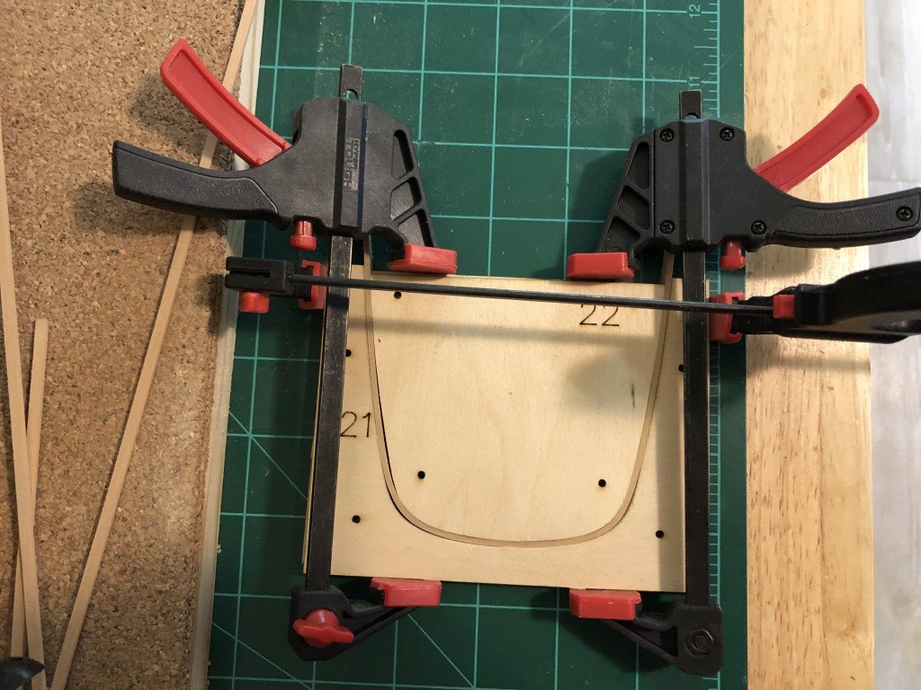
So a bit of sanding / filing to even out and true up the edges and finally I've a got a mold to try out:
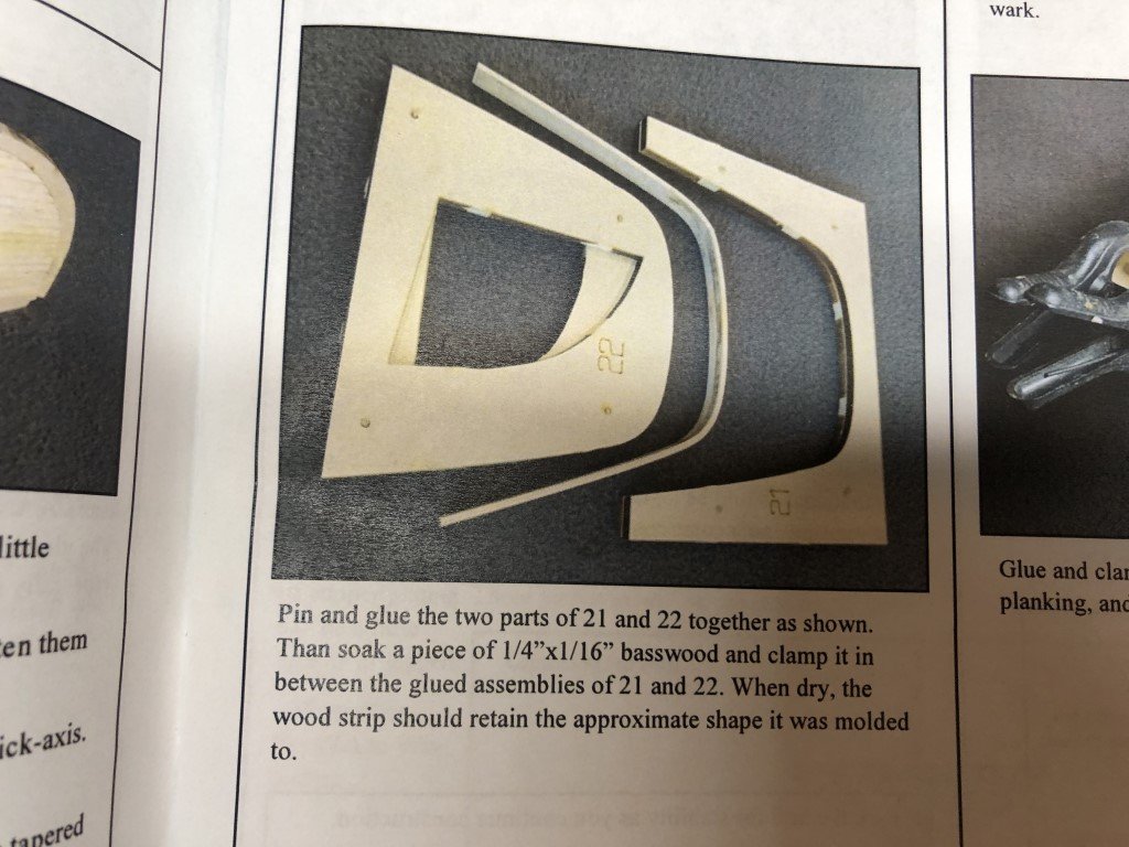
I cleaned up the laser char quite a bit so that when I mold the bulwark the wood won't get stained by char. The outside doesn't matter so much because it will be painted, but the inside will likely be left natural, so char dye would be bad. You can see in the instruction manual, that the char was not cleaned up and some was transferred to the wood.
So the mold is ready - wood is soaking as I write this - but it is a disappointment in the age of CAD and laser cutting, that the pieces that make up the mold needed so much work to get them ready for use.
-
I'm done smoothing the bulk of the hull as I am going to do. Time to install the bulwarks. I did decide to go with Costello Boxwood for this structure. Here is some material that I've milled / cut for the next steps:
I need two strakes (each side) of the 1/8" x 1/16" material. This will go from the bulkhead 9 to the front of the ship. The 1/4" x 1/16" material is to be bent into a u-shape that will fit from bulkhead 9 back to the stern region.
-
43 minutes ago, druxey said:
Congratulations on completing your model, Greg.
Lovely looking case. But might I suggest a couple of ventilation holes in the base covered with fine mesh to prevent insect entry? A sealed case is not good for a model.
Thank you very much!
The whole frame that holds the plexiglass panels lifts out, so there is some opportunity for some air-exchange between the frame and base inside the molding. Do you think that is enough exchange or should there be more? I have always wished that there was more information on case construction within forum - it always seems to be a bit of a mystery to me! It actually would be a nice topic for NRG to set up a tutorial and / or a nice article in the Nautical Research Journal.
Greg
- Keith Black, Ryland Craze, clearway and 1 other
-
4
-
Construction complete, the case is now just about ready for its finish.
After the picture was taken, I filled the finishing nail holes and a couple of 'almost perfect joints'. After testing a few finishing methods / colors, I've decided to go with two coats of Minwax cherry stain. I also made a matching cherry display board for the model to be attached to via a pair of brass pedestals.
Inching closer to the finish line!
- clearway and Keith Black
-
2
-
On 11/9/2024 at 2:04 AM, juhu said:
Great progress, will keep watching this thread for sure. Since I first noticed wooden static ship models and ME company I have admired their 1/96 Phantom kit and only wished it was available in 1:48. Yesterday I have found it just by accident. First I though there is just an error on the web with the scale
")
From what I see I agree with the notes - to enlarge the kit from 1/96 to 1/48 should involve something more than just "enlarging", i.e. adding the detail appropriate for the scale and proper plans. . From the pics available I think the cockpit area just sitting on the deck looks strange. As you said I would also suggest to burry it little bit. I am just not sure, to achieve this, would not it be better to cut space in the bulkheads before assembly? Or maybe I just see it wrong from the web photos.
Edit / added: I have been going through those few pictures from manufacturer website. If possible I would have one more question: how does the kit handle the whole anchor mechanism? I mean, I would expect this boat having anchor chain, but I see no windlass, no storage box for anchor on the deck, nothing. There are apparently some small winches directly at, I think called Samson post, but not sure this would be the answer for heavy anchors. Totally unfamiliar with pilot boats design, they still do resemble fishermen from Gloucester I have researched little bit, so am just wondering... Thanks a lot!
First - thank you for the positive comments!
I do plan on opening space for the cockpit prior to planking the deck. I'm not sure exactly how all the work will be done - one thought is to model the cockpit and its enclosure as a unit and then 'dropping' it into the model; this may be easier for me to handle than putting in a floor and then planking the cockpit and finally adding the sides. I have been giving this some thought!
I am no expert on the actual workings of this ship but as far as I can see, for anchor handling, there is a small windlass / winch that is attached to the forward bits, it is to have removable hand cranks. From the drawings / plans it appears that raising the anchor would be a two man job. There is a single anchor davit that is removable and can be placed on either side of the ship. It appears that a single anchor was used and that it would be stowed on deck. Some of this can be seen on the plans included with the model, the rest of this information is based on the practicum that Chuck Passaro wrote for building the 1/96 scale Model Shipways kit: https://modelexpo-online.com/assets/images/documents/MS2027-Phantom-Practicum-Complete.pdf - and I'm fairly confident his work is very well fact-checked.
- JacquesCousteau, reilly and juhu
-
3
-
I gave the port side of the hull a good sanding today and then brushed on a coat of 50% white glue to seal that side. Soon I can start working toward a nice smooth surface to paint and copper.
Thoughts for future steps in the build: Starting to think more about the bulwarks and deck. Currently I am thinking about a natural finish on the inner bulwarks, deck, cabins and such. Because of this, I am planning on replacing the kit supplied wood for the bulwarks and decking with something nicer. Probably Costello boxwood for the bulwarks and timberheads. Swiss pear may make for a nice contrasting margin planks and then C boxwood for the deck planking (I'm also considering maple for the deck). I also want to modify the deck so that the cockpit is dropped under deck level. I understand way this wasn't done on the 1/96 version, but would not have been hard to work in for the 1/48 kit. Also, I not be using the PE brass for the sides of the deckhouse, etc.
-
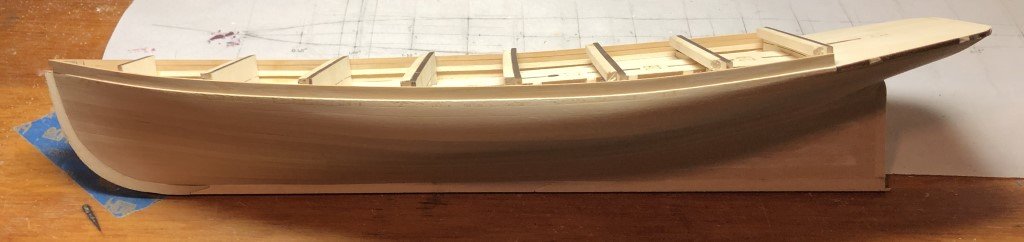
The transom has been planked and is partially faired with the rest of the hull.
I used 3/16" planks for all of this planking except for the top plank which is from 1?4" material. This time I remembered that the top plank needs to be positioned high enough so that the top edge fairs with the deck - been caught out on this type of situation a few times over the years! So the next picture is mostly a personal reminder.
Phantom 1868 by Greg Davis - Model Shipways - 1:48 scale - New York Pilot Boat
in - Kit build logs for subjects built from 1851 - 1900
Posted
Juhu -
I've learned a bit by consulting Chapelle's book 'Boatbuilding' - he writes "Cockpits in seagoing boats should be strongly built and, if self-bailing, should have scupper pipes of sufficient size to drain the cockpit quickly. The cockpit scuppers should be installed before the cockpit floor is laid. Cockpit scuppers should lead to just above the load water line. Cockpit scupper pipes are sometimes crossed, so the port scupper empties to the starboard, and vice versa; this prevents the leeside flooding."
I still have not found anything about the use of gratings; however if the grating were cut into the cockpit floor planking, then there would need to be another level of planking (or such) to collect the water passing though the grating. In the Volk, Davies-Garner picture, the grating is sitting on the waterway, so water could go through the grating and then flow on the cockpit floor toward the cabin where the scuppers would be located. This does make some sense to me - it would keep the helmsman standing above the water in some cases as the water drains away - but I am not a seafaring person, so just more guesses on my end!
Greg