


Greg Davis
-
Posts
351 -
Joined
-
Last visited
Content Type
Profiles
Forums
Gallery
Events
Posts posted by Greg Davis
-
-
-
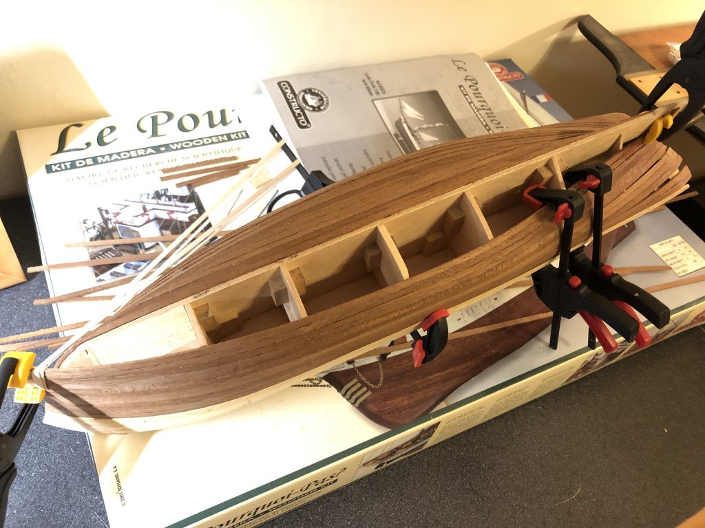
I've smoothed the hull as much as I am going to do. Spent a long time getting some nice lines by the deadwood. I also did some work on the stern. The supplied piece of plywood for the stern did not fit as nice as I would have liked, so I did a quick and dirty planking. I then filled the grain of the lighter wood with some artist modelling paste. There are a couple of rails that go along the sides that will be added after the stem is in place. I'll then prime and paint all of the lighter wood in an off-white.
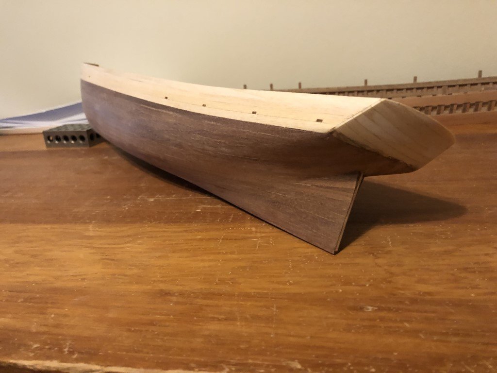
Next up will be fitting the stem and keel. Once the keel is in place the hole for the propeller can be opened and preparation for finishing (staining and coppering) the lower part of the hull can be made.
- BobG, clearway, Prowler901 and 1 other
-
 4
4
-
We just got hit with a cold snap over the past few days - didn't even make it up to freezing for a couple of days. But how can you complain when parts of New York State have gotten up to 6 feet of snow!
-
-
Druxy -
Thank you for the input.
The reason I thought to bend them is that the beams will be 6 mm wide and 2.25mm thick, the longest are to have chamber of 9mm. Because they are relatively thin with respect to the width, I thought that cutting them out of 6mm thick material would be challenging. But then I have considered making a pair of metal plates to sandwich the beam blanks and then sand / mill them to shape. This could be used to make a single beam or a longer piece that would be parted into separate beams. There are 28 beams in the vessel and they need to dovetail into the ledges, so I'm sure that I will be making 35-40 beams before I like what I need. Maybe the time spent on the making the plates would be well spent - especially to maintain consistent deck camber.
Greg
- mtaylor and Keith Black
-
2
-
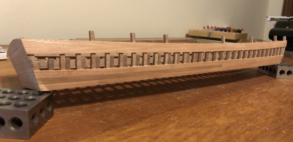
I finished planking the port side and have given it two rounds of smoothing; first with 100 grit sandpaper and then with 150 grit. This is how it will stay until the 'bolts' are in place. At that point I will do the finish sanding as it will be more difficult to do so once the doublings have been added. Final contouring of the top edge is also on hold, until the deck beams are in place.
Next, I will work on partially planking the starboard side.
I know there are a couple of tasks to take care of before the deck beams, but I am trying to decide how I should construct them: cut them out individually, shape a larger piece of wood to the proper camber and then slice off the beams, or create a mould and bend strips to the correct shape. The mould method might be good practice before making the planking for the two dredger wheels ...
-
-
The good: all the planks are attached!
The bad: at the start of October I thought I would have 4 - 6 weeks to complete the planking and then spend some time outdoors sanding the hull; 6 weeks have gone by and it looks like I missed the outdoor sanding window! Today started out warm and sunny with temps into the low 70's; now the weather is turning - its raining and the temp is to be dropping all night and into the morning when it will be very close to freezing. The 10 day forecast doesn't make it into the 40's for the high and goes into the 20's (or teens) every night.
Looks like the basement beckons with dust mask and dust collector - not as much fun as I had hoped for.
- clearway, bruce d, Prowler901 and 1 other
-
4
-
I appreciate that!
It really helps to have regular time to work on my models - these first few months of retirement have been wonderful, I hope it stays this way for a long time!
- Keith Black, James G, mtaylor and 1 other
-
4
-
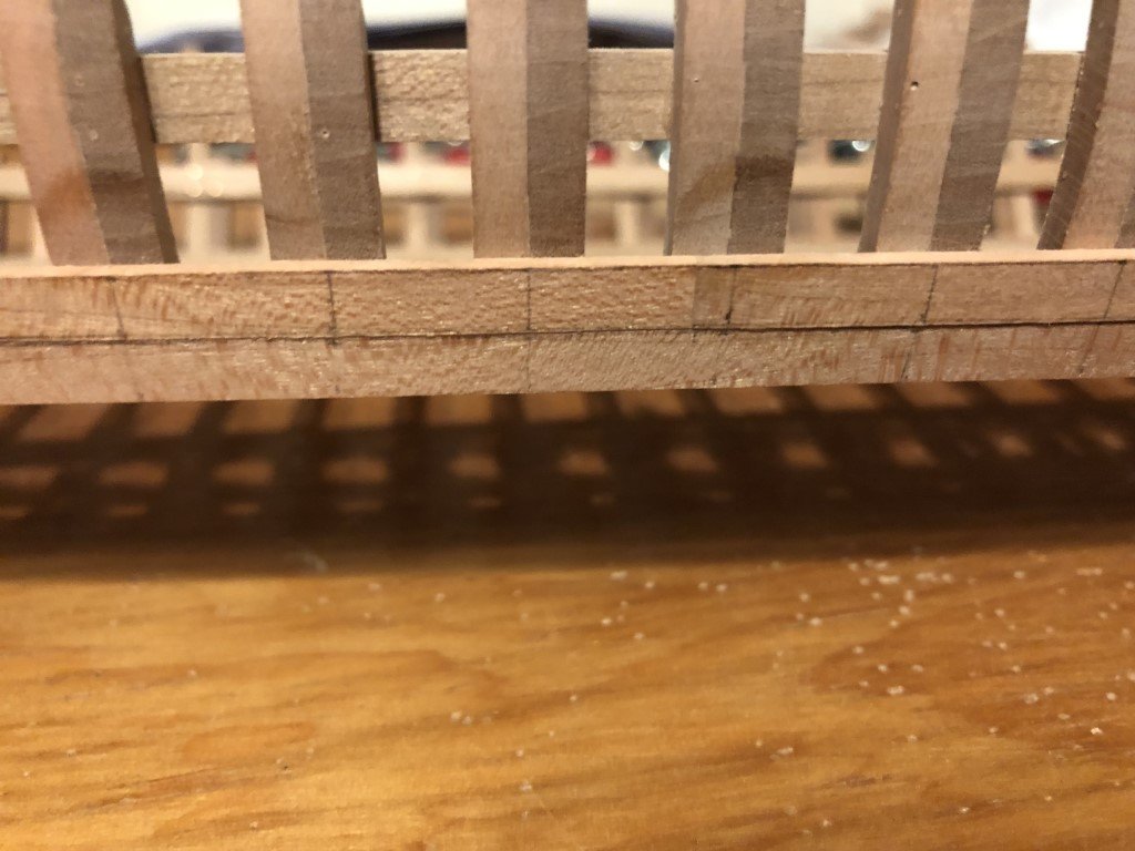
The lowest strake was made from one piece of wood so that I could get a nice starting position and any joints would not be seen as another layer of planks will go across this part of the vessel.
Starting with the next stake (second from bottom) I will be respecting the proper location of planking butts. This particular strake is to be made from two planks joined at frame 14. I chose to join the two blanks for these planks before laying out the shape. In the following picture, the juncture is just to the left of the vertical line marking the line between the timber top and knee for frame 14. The horizontal curve is a tracing of the upper edge of the first completed strake. The tracing being done before fastening the first strake to the vessel - this simplifies the spiling process (for me).
I then marked the height of the strake at each frame and drew a smooth curve through them, cut the top edge and smoothed to the final shape. Before attaching this stake to the model, it was used to mark the lower shape of the next strake on another blank. Once attached to the dredger, the plank joint looks good to me. In particular a nice smooth curve has been formed over the joint area - something that is not real easy for me to achieve when making the joining planks independently.
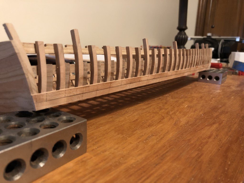
Finally, here's a look at the lower two strakes in place - already 25% of this side done!
- Charter33, Keith Black, mtaylor and 7 others
-
10
-
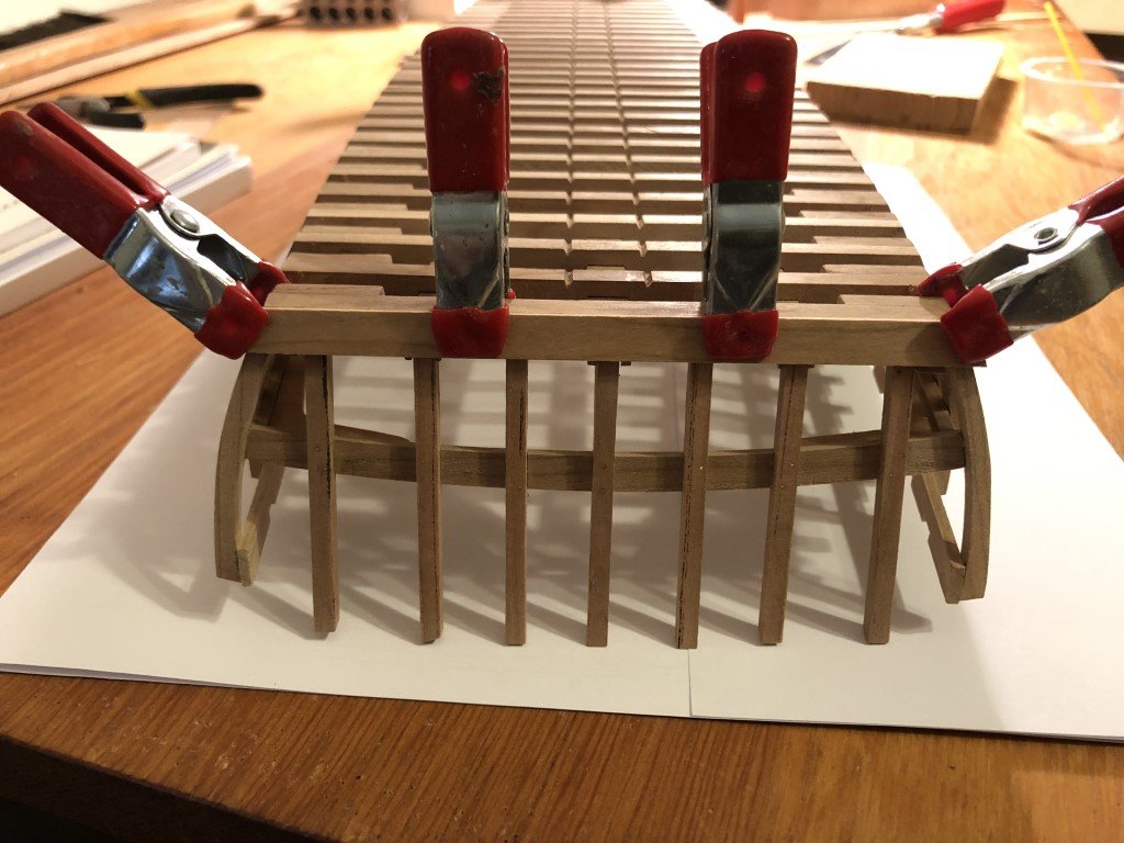
I made up plenty of planking material today and have started to form the lowest plank for the port side of the vessel. First I clamped a piece of planking material to the lower part of the side and marked the contour of the bottom of the dredger on it. This shape was then cut on a scroll saw and refined with an oscillating spindle sander. Then the piece was re-clamped to the side and final adjustments to the lower edge were made to give it the correct curvature.
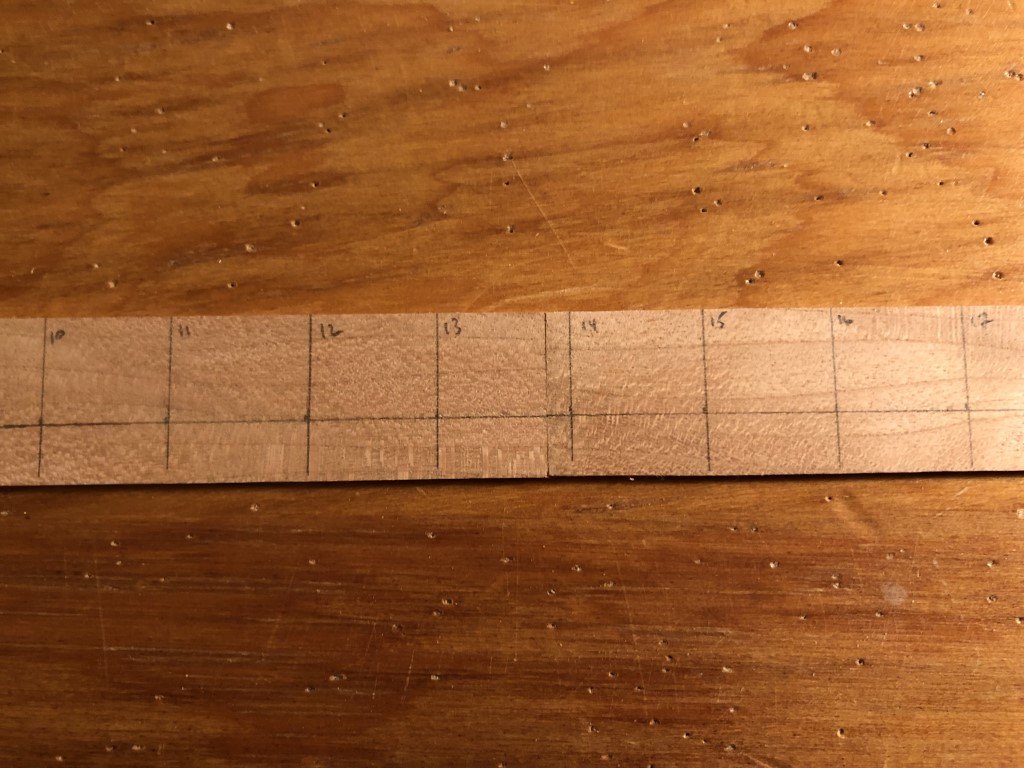
I've measured and recorded the total height of planking along each top timber. These measurements were then divided by 8 to determine the width of each plank as it crosses each frame. The frame locations were marked on the plank that is being developed. The width of the plank at each frame was noted along the frame locations and a flexible strip of wood was used to guide a smooth curve through the points. Tomorrow the upper edge of the plank will be cut, smoothed, and prepared for fitting.
I will be planking all of the port side and leaving a portion of the starboard side open for internal viewing.
- Charter33, CiscoH, G. Delacroix and 7 others
-
10
-
First - thanks for all the support that you have been giving me!
Over the past couple of days, I have been able to plank the bow and stern faces. I'll take care of the bolts and finish sanding later.
It looks like this week the main activity will be working on planking the sides.
-
Slowly but surely the planking continues. As of today, there are 4 more strakes that will be challenging to get in place. After that the final planks and stealers should go in quickly and hull smoothing will commence.
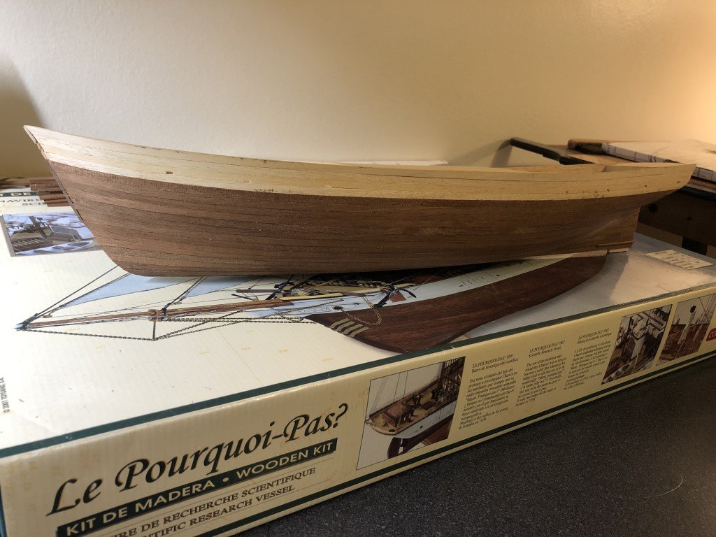
To learn more about the ship, I ordered a copy of: The Voyage of the 'Why Not?' in the Antarctic: The Journal of The Second French South Polar Expedition, 1908-1910 by Jean Charcot. The first paragraph of the introduction indicated that the exterior had armor-plates and thick galvanized iron sheeting. From what I can gather from the MSW forums, iron sheeting seems to be a challenge to reproduce and is often replaced with brass or copper. Thus, I feel safe to go with my original idea of coppering below the water line for this model to represent metal. This will cover the un-scale like planking below the waterline.
-
Today was nice here - 70 degrees - and I was really sore from moving huge rocks yesterday, so I got the day off from 'chores'! That gave me the chance to sit outside and finish the basic exterior fairing of the dredger's hull. This was done with 100 grit sandpaper. After the bow and stern areas are planked the sides (and bottom) will get a bit more smoothing with a finer grit.
I also made up the 1.5mm material needed bow and stern planking. The first (bottom) stake - front and back - has been attached. The next five strakes are straightforward. The one that follows needs to have 2 lights / windows cut in and the last (top) strake takes on the camber of the deck.
- steamschooner, Charter33, druxey and 8 others
-
11
-
Jim -
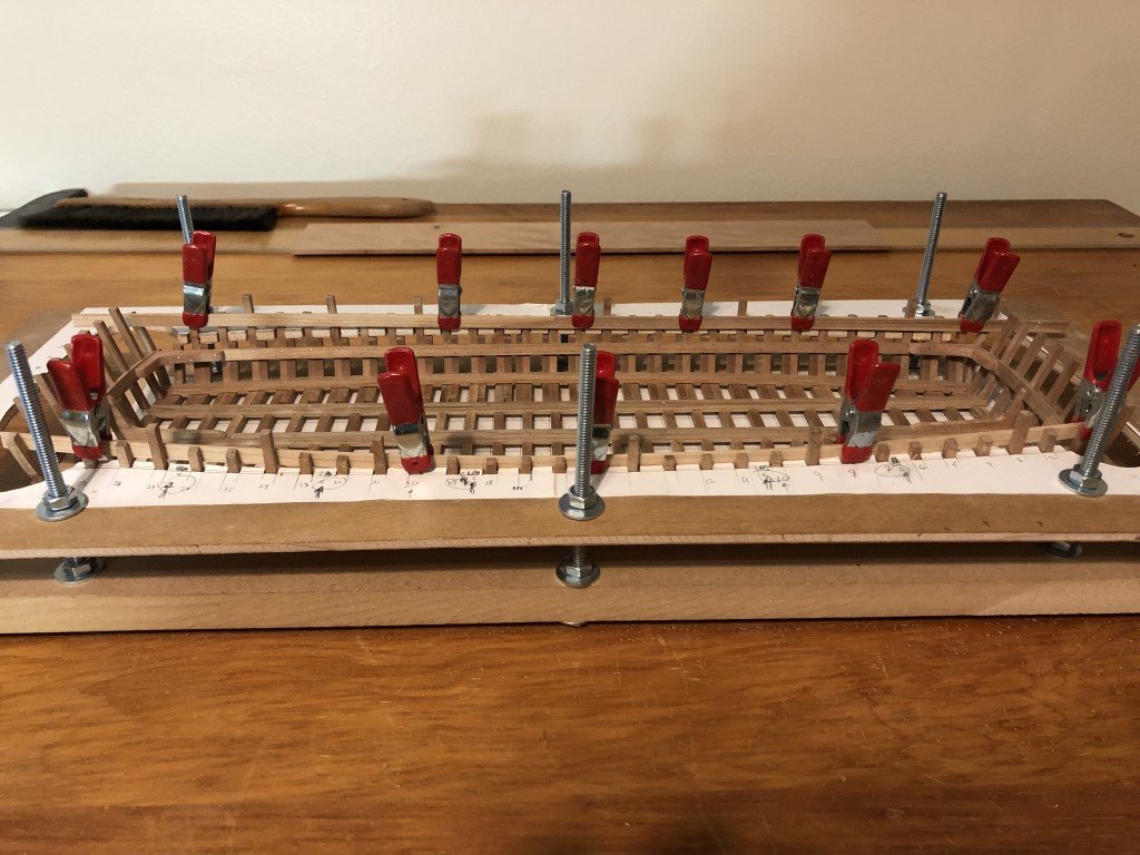
This type of jig is often used in model ship construction - it just seems that others are not using such for their dredger and / or Emma Berry models. I think that for any framed models I work on, A jig will be a necessity! (And I find no shame it that.)
Greg
- mtaylor, James G and Keith Black
-
3
-
-
Today I released the hull from the jig I have been using - its really satisfying to see the work done so far sitting freely on a table!
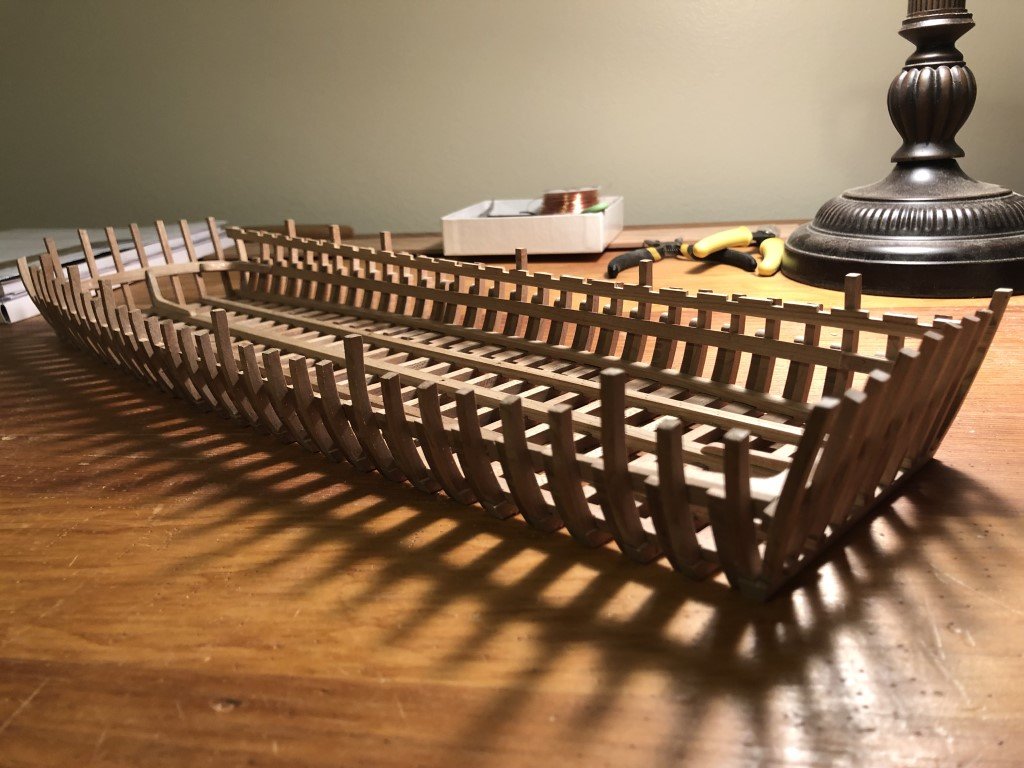
The structure feels quite stout already, but I will feel even better once the bow and stern faces are tied by the exterior planking.
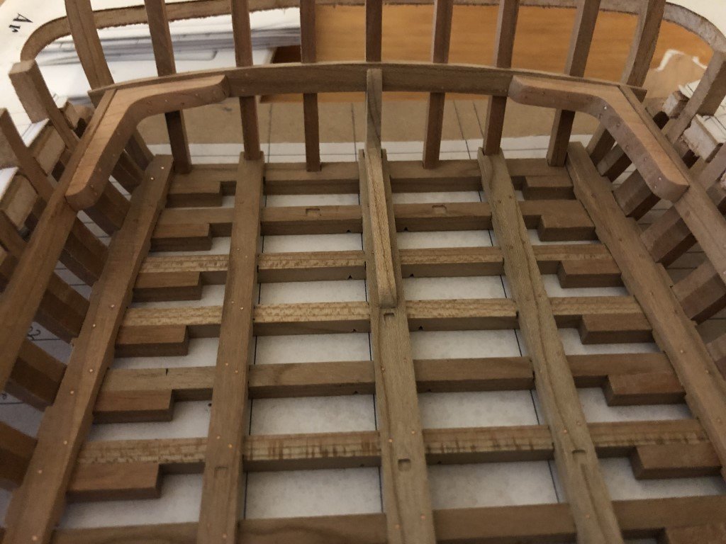
One of the sheer clamps is in place, the other will go on later this evening or tomorrow. Milling the dovetail recesses for the deck beams went well - I think I spent close to 6 hours in total for the work.
-
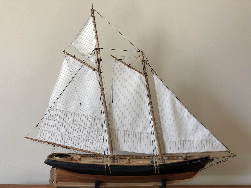
The America kit provided plans and material for the sails (as it does for Le Pourquoi-Pas?) but I thought the fabric was too heavy, so I eventually got some sail cloth from Model Expo to make the sails. I also tried a number of different threads - weight and color - before all the sewing took place. It took me more than a few days to sew all the lines and reinforcements. Then more work for the reef points!
These are the first sails that I have made for a model. I was probably close on 10 years between when I made and rigged the model before I got up the nerve to make the sail set. In fact, it was suppose to be practice before I made a set of sails for my model of Britannia. Still not sure when I will attend to that project - it carries so much sail.
-
Keith
The Constructo plans show that on each side there are 17 belaying pins along the rails midship between the fore and main masts, and 6 cleats near the mizzen mast (3 before and 3 after). The belaying plan indicates the use of of these for braces. I really have no idea how realistic the provided belaying plan is - most likely it is simplified / standardized for kit usage. Also, the provided plans do not show the shroud pin racks.
The way the hull wood finishes is one of the things that attracts me to Constructo (and some other European) models. While the models are a bit short on detail and some features are clearly out of scale, the overall presentation often looks nice to me. For example, here's a picture of America that I made from a Constructo kit:
All the best,
Greg
-
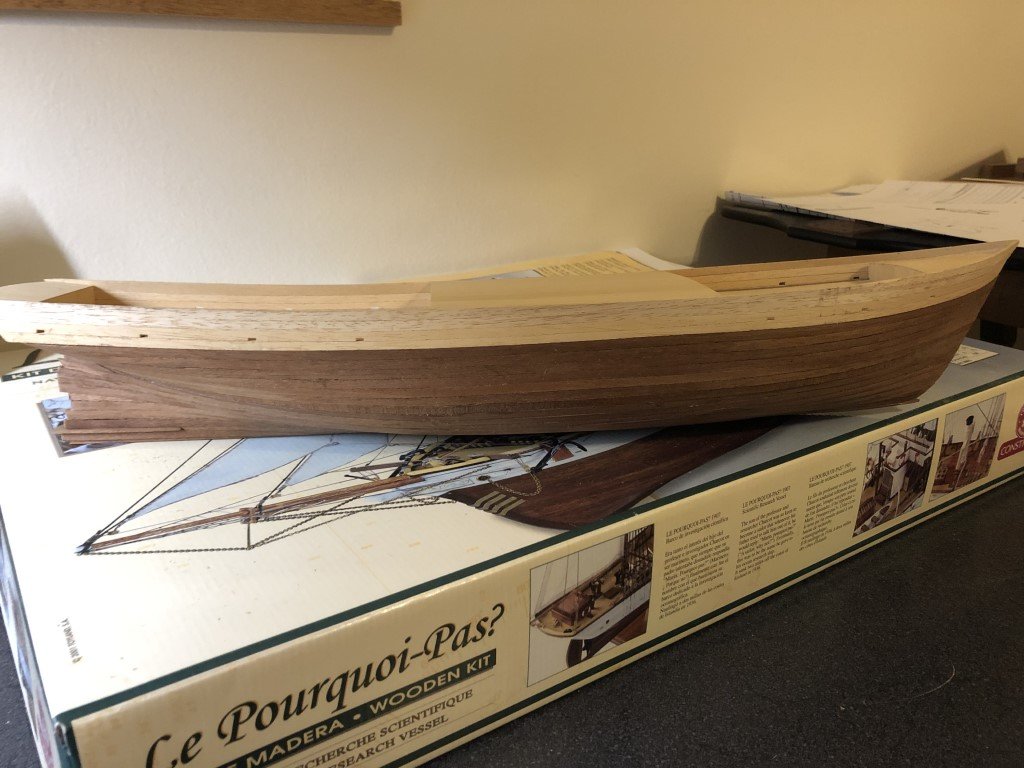
I've finished planking the port side of the ship today. Now I will turn my attention to the last dozen or so strakes needed on the starboard side. Then the big sanding job commences!
At this point I am planning to copper the ship under the water line. I will most likely paint the topsides and leave the intervening region with a natural finish.
-
-
I went ahead and milled some wood for the sheer clamps and made the scarf joints for each. Here are a couple of pictures - one of a joint and the other showing the dry fitting of the clamps.
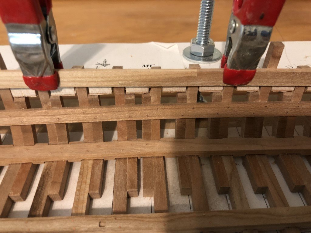
Next I will mark and cut the dovetail notches for all of the deck ledges.
-
I think my brain was turned off when thinking about the grain direction. Assuming that it is most likely that there is failure along the grain, then the best choice would be the grain running diagonally between the pieces being joined. I guess in this manner if there is a split, there would still be sub pieces of the knee forming a joint. Whereas if the grain radiated from the corner of the two pieces being joined, then there is the possibility that the knee would split radiating out of the corner resulting in one piece of the knee contented to each side of the joint, yet with now no (or little) material connecting / bracing the joint. ☹️
-
I agree and will give that a try for the remaining knees that are visible on and above the deck. However, if I do so should the grain radiate from the corner or should it form hypotenuses with the sides, i.e., create a bunch of triangular shapes? Also, I don't have any compass cherry to use for this task.
In the meantime, the four corner knees are installed and bolted. Also, I have installed the two knees that join the keelson to the bow and stern structures. Once these two knees are bolted, I will move to the next step.
I think there is a choice of two different routes at this point: begin planking the exterior or installing the sheer clamps.
Assuming that I am reading plans correctly, the order of (exterior) planking that makes most sense is
1. bow and stern faces
2. sides
3. bottom
4. doubling of the planking below the water line
5. the wale - but this isn't to be done until the deck has been planked
So, I could go ahead and at least plank the bow and stern faces. The sides would then need to get their final fairing before moving on. It is right here that I think installing the sheer clamps first would be a good move. The clamps would give additional stability to the upper portions of the frames for the fairing process. In fact, it might be a smart move to put in the sheer clamps and then fit the uprights for the wheel gantries. This way, the uprights, which have lower portion shaped as a frame could be faired to fit nicely between the sheer clamps, side strakes, and curved carlings.
I hope I'm not thinking out loud too much here! I think that I just may have convinced myself that the sheer strakes should be the next (sub)project.
- mtaylor, GrandpaPhil, James G and 2 others
-
5

A Port Dredger 1750 by Greg Davis - FINISHED - Scale 1:36
in - Build logs for subjects built 1501 - 1750
Posted
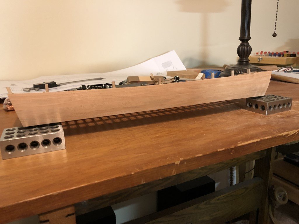
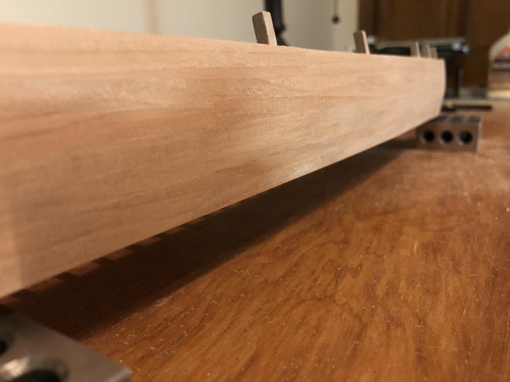
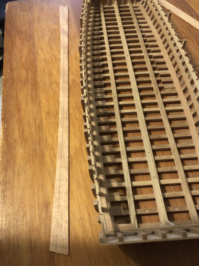
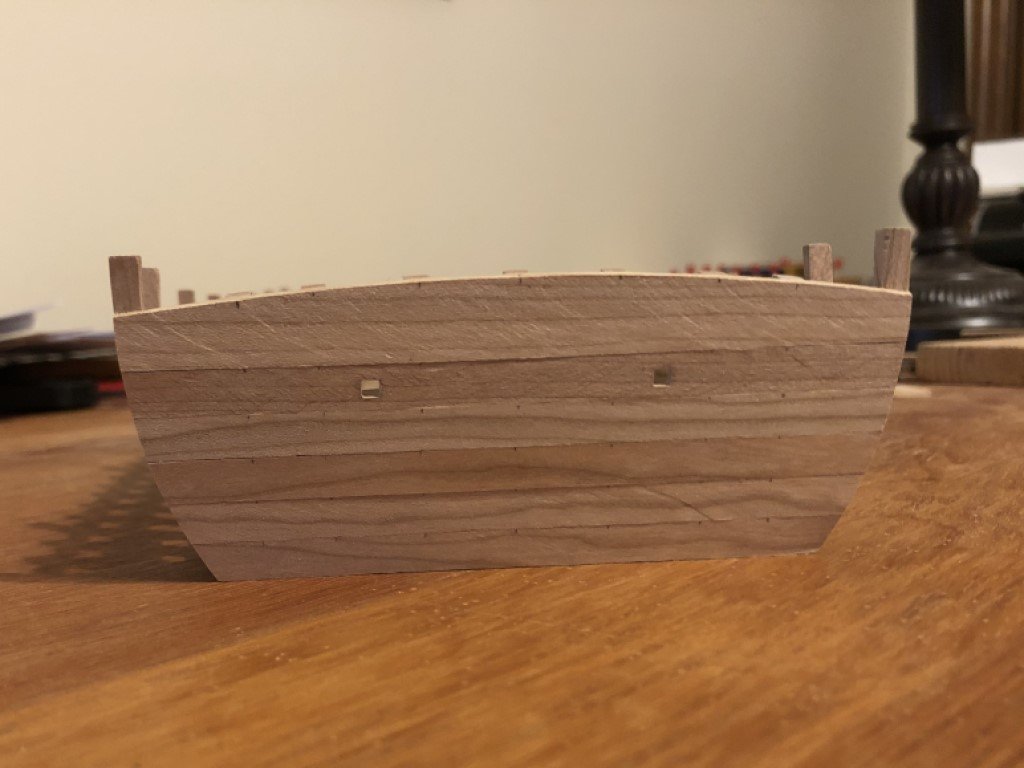
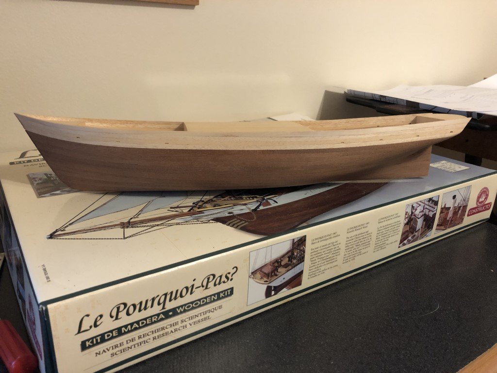
The bottom is planked and the five planked sides have all been smoothed to a state that the multitude of plank fasteners can be added. The keel is also complete, but I didn't want to put it in place until after the rest of the bottom work was completely done. In this way it will be easier to have both sides of the bottom to have the same thickness as I can use sanding blocks the span the whole width.
Here is a current view from below:
And a view from above:
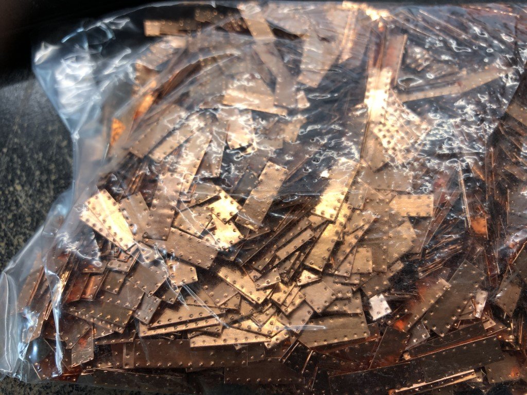
Time to get the #74 drill bit and the copper wire out - this is going to take awhile!