HOLIDAY DONATION DRIVE - SUPPORT MSW - DO YOUR PART TO KEEP THIS GREAT FORUM GOING!
×


SJSoane
-
Posts
1,649 -
Joined
-
Last visited
Content Type
Profiles
Forums
Gallery
Events
Everything posted by SJSoane
-
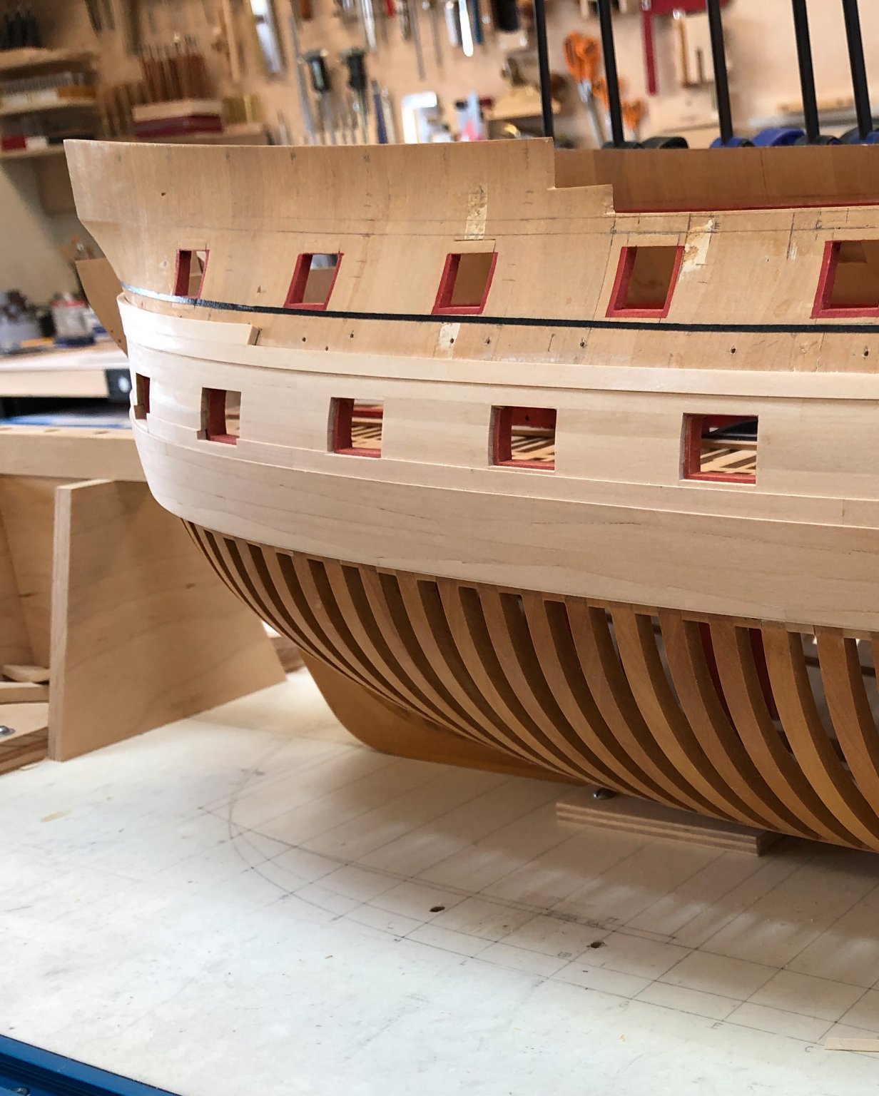
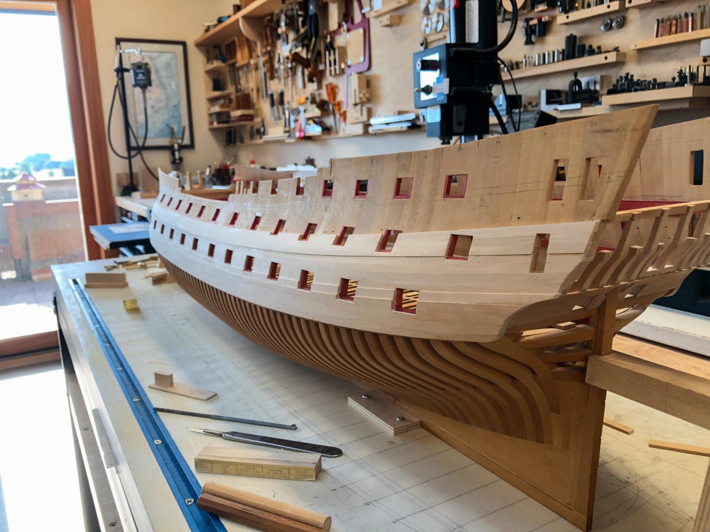
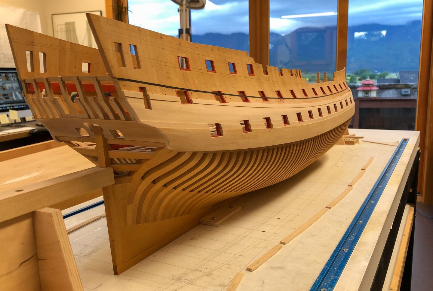
 Thanks so much for the kind comments, Gaetan and Steven. I have now completed the starboard channel wale, which is as far as I will go with planking for a while. I need to catch up inboard, and get the remaining decks in place before planking the topsides. I don't want to risk errant drill holes coming through from work inboard. Here we can see again the dramatic resolution of various curves at the stern, as the tumblehome twists upright for the stern works. I think it is now on to spirketting on the gundeck, and perhaps proceeding with the cheeks and hawse liners at the bow. Once those are done, I can finally drill the hawse holes, something I have been looking forward to for many years! Mark

-
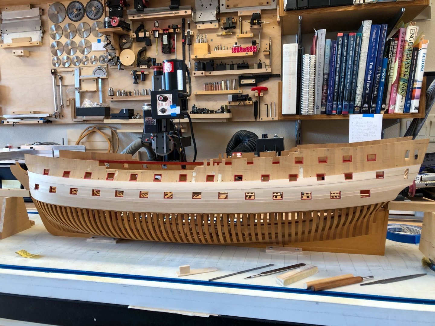
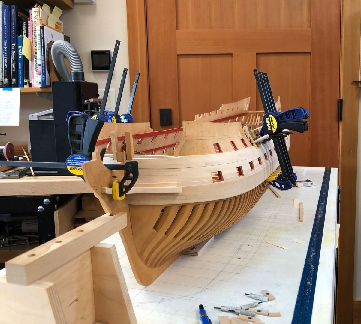
Thanks, druxey, Christian and Steven. It is slow progress, and encouragement really helps! Big day today. I finished the channel wale on the port side, and only 3 pieces to go on the starboard. Here you can really see how the hull twists from midships to the ends fore an aft, as the tumblehome flows into more vertical surfaces toward the extremities of the hull. I just did not see that staring at the drawings for so many years. It is a masterpiece of design, how everything blends so beautifully. Those guys were good! I remember Remco's Kingfisher postings, with the tag line at the bottom: "Treat each part as if it is a model on its own, you will finish more models in a day than others do in a lifetime." This kept me going, as each single plank seemed to need as much attention as more interesting parts like deck fixtures. And yet, after all the work, it just joins innumerable other pieces just like it. It is like counting down the miles or kilometers on a long road trip! Mark
-
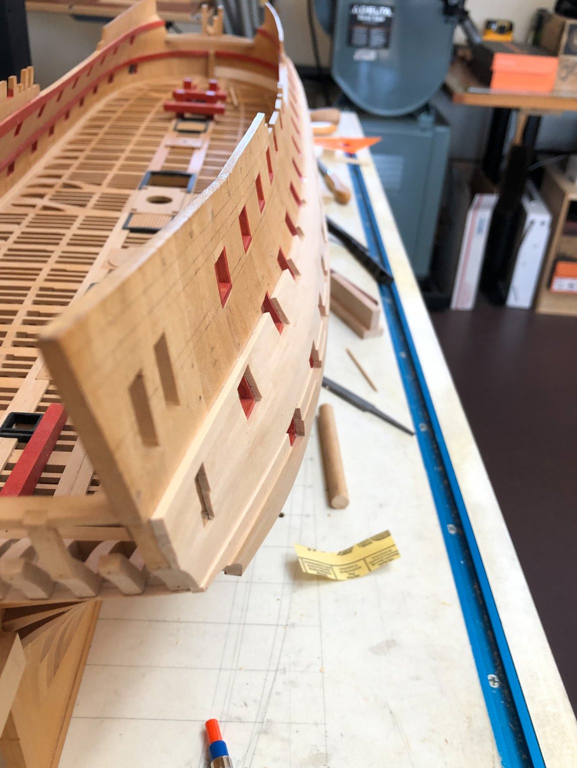
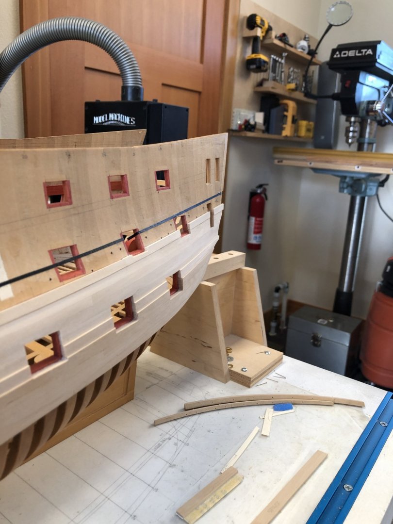
Thank you, Mark, druxey, Siggi, Shipman, Gary, and Leopard. As usual on this project, I will need to get a selection of materials and see what works best for me. I really want to look closely at a number of contemporary models to see how they did the white decorations. I have always felt like the 2nd Bellona model, recently shown here by Mark and by Siggi, has a pretty strong bright white, maybe too bright for the muted tones of the rest of ship. But maybe that is because the other colors faded. And I do notice that some of the ivory detail is shaded, maybe by dirt, or maybe in the natural color of the material. The mammoth I am not so sure of....😗 Of course, I can't get to any of that until I finish the $%&xx channel wales. So here is progress on the upper most strake, now wrapped around the bow. I still have to level some of these surfaces, and refine the lower edge of the wale. But I am making progress. The top two strakes at the bow take a wicked twist, as they wrap from the tumblehome into the reverse curve designed to hold the anchor clear, in a very short distance. And, they go from an upward sheer on the side, to a reverse sheer right at the bow. On the uppermost strake, the upper surface also twists dramatically, to keep it at right angles to the frames at every point. Artist's tape was my friend here, to fair the upper edge: And here is the progress on the port side. You can see in the first photo below how the sides twist from the tumblehome to the outward projecting corner in the length of just a handful of frames. And you can also see how the small deck at the beakhead cuts horizontally across the uppermost plank, stopping that plank from completing the natural sheer of the sides. There is some discoloration of a few planks at the bow, caused I think by the steaming process and not enough sanding yet to clear it. Or, it may be the oxidized color that all of the wood will go to eventually, since I cut some of these out of blanks that had been sitting around long enough to oxidize. We will see! Best wishes, Mark


-
Thanks, Siggi, I will have to try painting some white and see how it looks. The ivory sometimes looks too white, and so white paint will look a little more subtle or more soft. Mark
-
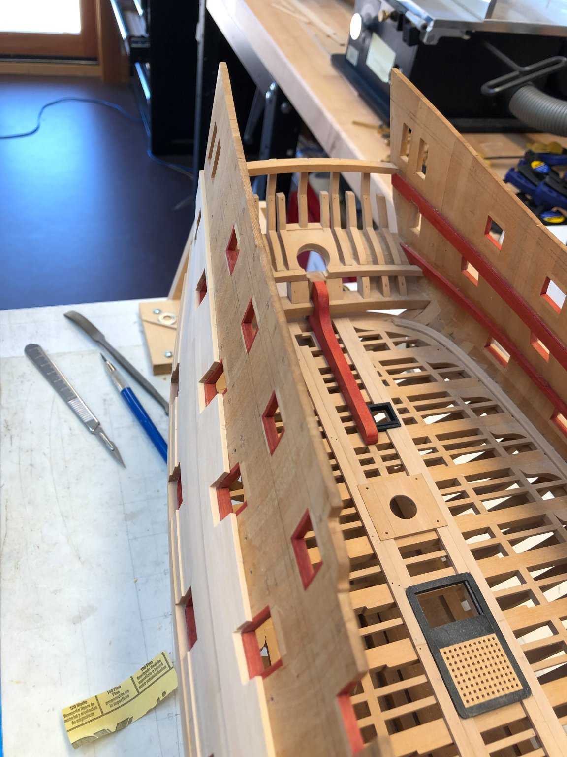
Thank you Gary, druxey, Mark, Marc and Siggi, this really helps me. It does seem clear now that the small cabins either side of the steering wheel are red, while all of the captain's rooms are white. Funny, you can look at a photo many times and not see something right in front of your eyes, if you were not specifically looking for it. I will have to try some experiments with white paint. Examples I have seen at one extreme look thick and garishly white, while at the other extreme, thin and blotchy like the first coat of paint on plywood without primer. I got some White from Admiralty Paints in England, and will try at some point airbrushing it onto raw wood with various percentages of thinning. And if I can't get a good finish, I will look at using Siggi's Humbrol Matt 65 green. Related to that--the issues never end, do they?--I have to think about how I will construct the various ornaments on the stern which were originally made of ivory. Since ivory is no longer appropriate, are those boxwood painted white as well? I just glued in the uppermost, foremost planks of the channel wales, the last curved outboard planks on the ship. I might be able to retire the steamer permanently, once I finish the spirketting and quickwork at the bows! Best wishes, Mark
-
Hi Mark, thanks for catching that! I have regularly been looking at the Princess Royal in Rob Napier's book for model construction details, and it has black spirketting and natural quickwork. I guess it just sort of soaked into my head that I would be doing the same. But more accurate to follow the Bellona model, of course. I can see from my photos of the second Bellona model that spirketting and quickwork are red on the upper deck and on the exposed areas of the quarterdeck and forecastle ; I assume it is the same on the gundeck. And do you know if it is also red in the captain's cabin? I had it in my head that this needed to be a green color, but I don't recall where I saw that or what the exact color would be. Indeed, I have not yet installed the deck clamps for the poop deck, because I wanted to color them the final color before installation. Given that the spirketting and quickwork would be red, then I would need to use my usual red dye; so druxey, your advice is doubly important here. I have no way to do red except as my dye. All red does simplify coloring around the gunports, since it just wraps around the edges. Mark
-
Hi Gary, I realized, as I looked forward, that I have been avoiding the question of the spirketting on the gun deck. I can't get a lot further until I deal with this. So, time to think about how to do it. I'll have a look at your great job again. A big challenge is how to color it black. I know from the external planking that the outer face needs dubbing down to form a smooth surface out of the individual planks abutting each other at an angle. So, how to install the spirketting, smooth down its surface, and then color? I have used shoe dye for all black on the project so far, but I am afraid it would run into the waterway. Maybe color the edges before installing, then smooth, then color the middle? Or, mask and spray paint. Good thing we never run out of issues to address, or life would get boring! Best wishes, Mark
-
Thanks, Gary and druxey, when I get another spare slot of time I will try another maquette, this time larger. I am also awaiting shipment of carving chisels from Mihail Kirsanov, which by all accounts on this website are the perfect tools for undertaking miniature carving. I will finish the last strake of the channel wales, and then put aside planking for a while. Carving will be a nice contrast to the tedium of planking! Shipman, I remember walking through the Neptune Hall back in the late 1970s. It was the first maritime museum I had ever seen (I grew up almost a thousand miles from an ocean). I was overwhelmed by row after row of models; like a kid in a candy store, I rushed from one model to the next, and then back again to favorites. I could not get enough. And therefore how disappointing when the museum switched to "interactive general public" mode years later. In light of your question about the Prince, I wonder if anyone has published where individual models from Greenwich and the Science Museum are now located, not just the museum location, but also whether they are in storage or on public display? Mark
-
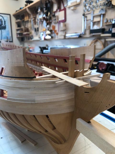
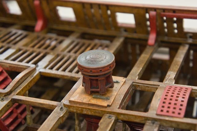
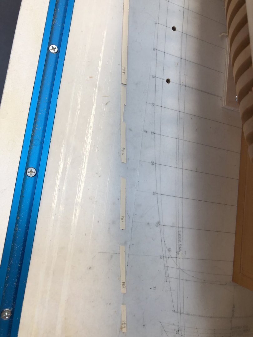
A small update. I finished the first two strakes of the channel wales, and I am moving on to the 3rd and last. However, the first plank at the bow is cut thin because the small deck at the beakhead bulkhead sits horizontally, not according to the sheer of the profile and the rest of the planking. But this little deck also has the same roundup as the upper deck over which it hovers. So, what is the actual line of the upper edge of this last plank? To figure this out, I temporarily installed the beam at the aft edge of the small deck, and also the first beam in the head timber structure. The deck needs to align with both of these. I then measured down from the temporary deck plank shown here, to the top of the previous plank, to determine the width of the third plank at the bow. The deck is actually rabbeted down from the top of these beams, so I will have to cut down the thickness of the deck planking as well. I should have widened the second plank to reach up to this edge, but I didn't really think this through at the time. No problem, because a thick batten used to mount the grating over the head will eventually cover this joint. A fun diversion from planking! Mark
-
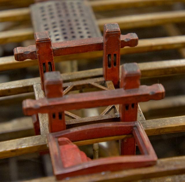
Hi Hamilton, Just to make life more interesting, the HMS Bellona 1760 has serpentine shaped hatches and gratings, as seen here in the contemporary model. Mark
-
Thanks, Gary and Mark, I had never noticed that before. Very interesting detail. I looked around some more to remember why I thought the Bellona had angled and hooked spirketting. I found it in Brian Lavery's Anatomy of the Ship for the Bellona, page 46. It is redrawn from a drawing of the Arrogant 1761, just a year after the Bellona, and also designed by Bellona's designer, Thomas Slade. I looked for the original online at the National Maritime Museum site; it lists the drawing, but there does not seem to be a scanned image available. So I guess I will work with Lavery's redrawing. Would have been fun to try something different.... Best wishes, Mark
-
Thanks, Gary, that look great. I haven't noticed those keyed joints in the spirketting before, as opposed to sloped scarphs like in the beam clamps. I had it in my mind that the Bellona would have sloped scarphs, but for the life of me I don't know where I got that idea since there are no Bellona drawings showing this detail. I have a jig for steam bending the planks outboard at the bow; I'll try it for inboard as well and then adjust accordingly if there is too much springback. Best wishes, Mark
-
HI Gary, I was looking back in your build to see how you did the spirketting on the gun deck, but I can't seem to find it. I am beginning to think about doing this once I finish the channel wales, and you have always been an exceptionally good guide for me! I am particularly interested in the bow, and how to steam bend those into place. Do you recall what you did there? Mark
-
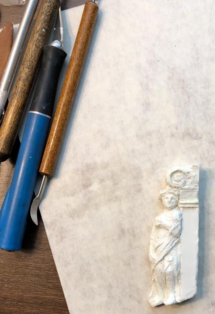
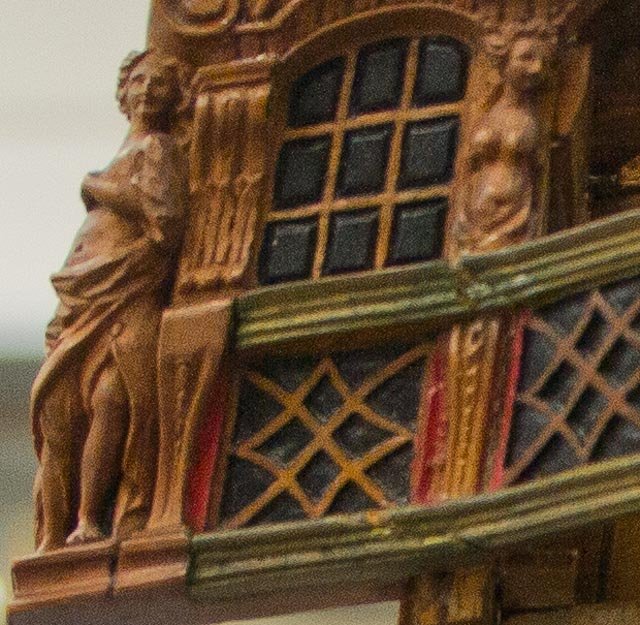
Thanks so much, Michael and Greg. I am sure I would have been fired many years ago if I was an apprentice to an 18th century ship model builder. Can't earn my keep! I had to spend a night in a hotel earlier this week, and took the opportunity to try making a maquette of the sculptures on the stern of the Bellona. Even though I made this at twice the scale of the model itself (3/8" = 1'-0" instead of 3/16" = 1'-0"), I still did not have clay modeling tools small enough; and the clay was too soft and deflecting. So another round needed with better tools and clay. But this did give me a sense of what it is like to shape in 3 dimensions, and to see the figure itself in 3 dimensions. An entirely different world for me! Best wishes, Mark
-
Hi Gary, Happy birthday! Your arrangement for the transom at the stern looks very convincing. Well done. I will not complain any more about how tedious is is to plank, when I see those crooked hanging knees! Beautiful craftsmanship, as usual. Best wishes, Mark
-
Thanks, druxey, I am going to break out the clay today and see what is what with this maquette process! I forgot to attach the following image yesterday, showing the first strake of the channel wale complete on the starboard side. Work progresses on the second strake on the port side. Mark
-
Gaetan, Beautiful, finely crafted, a work of art! You are an inspiration. Mark
-
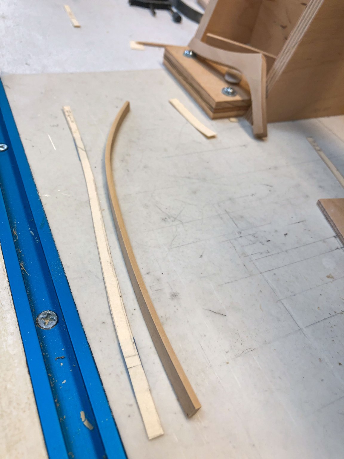
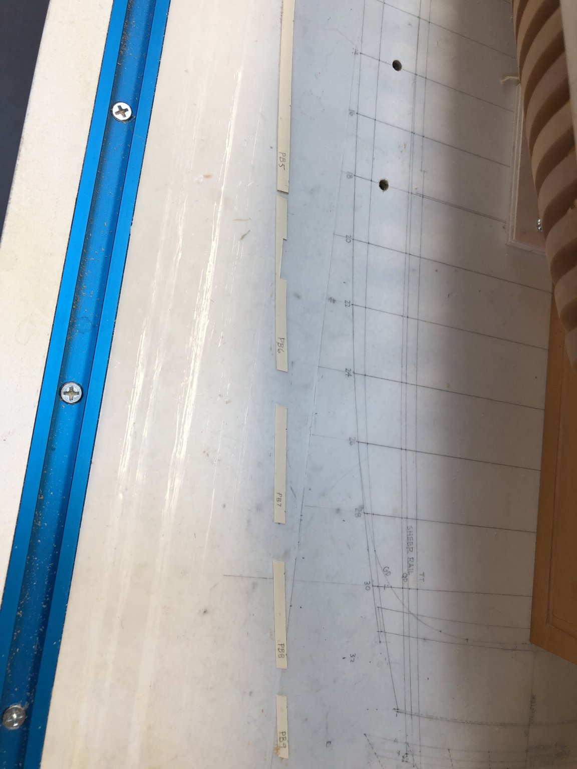
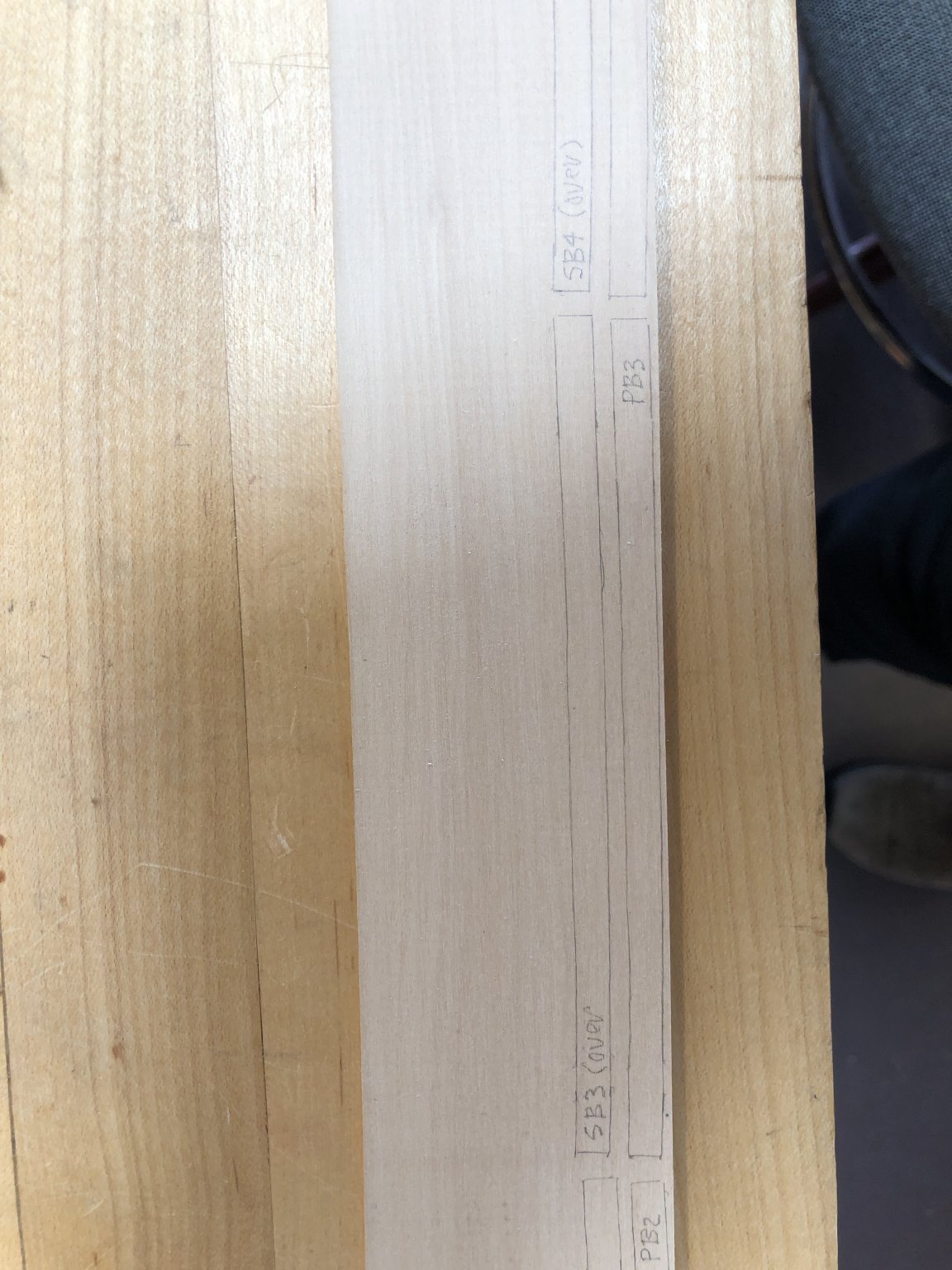
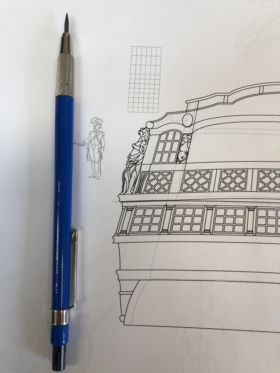
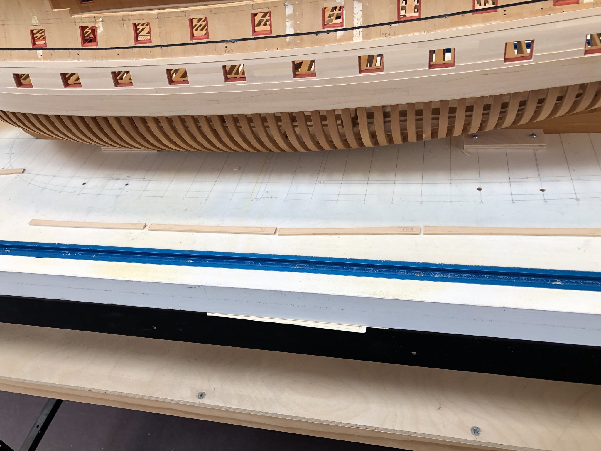
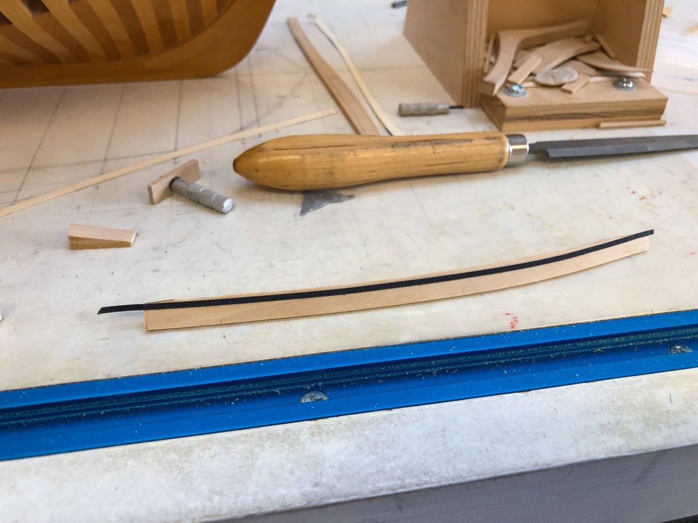
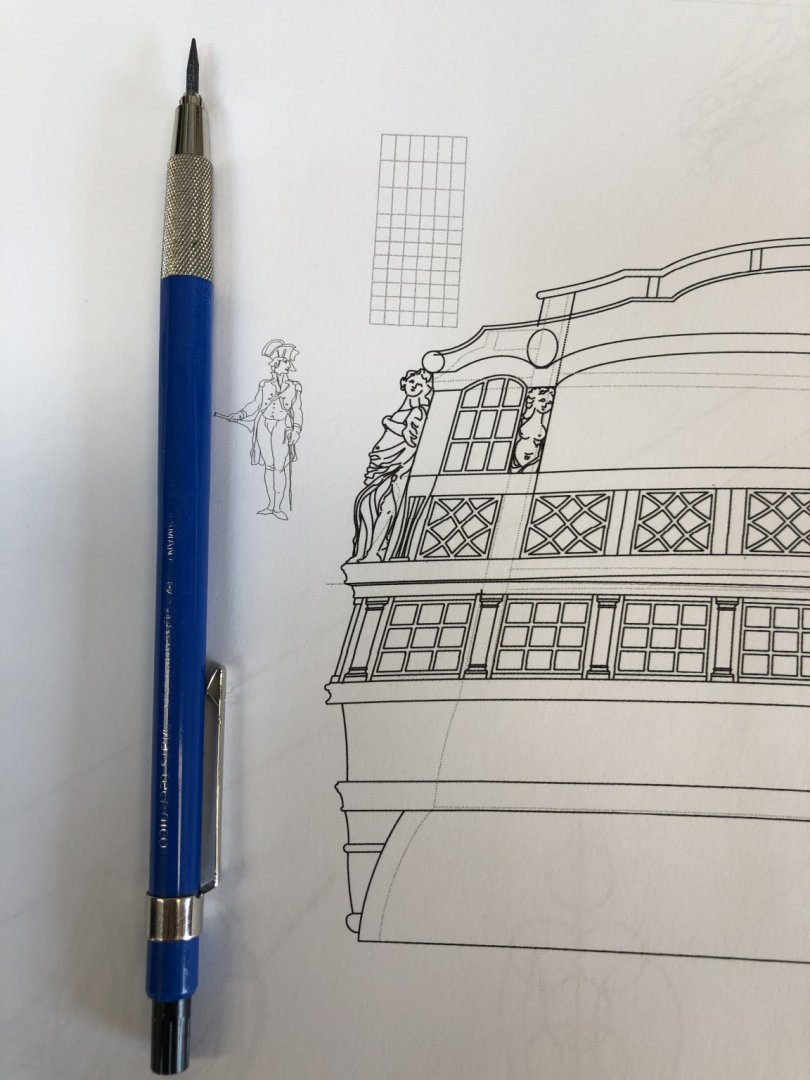
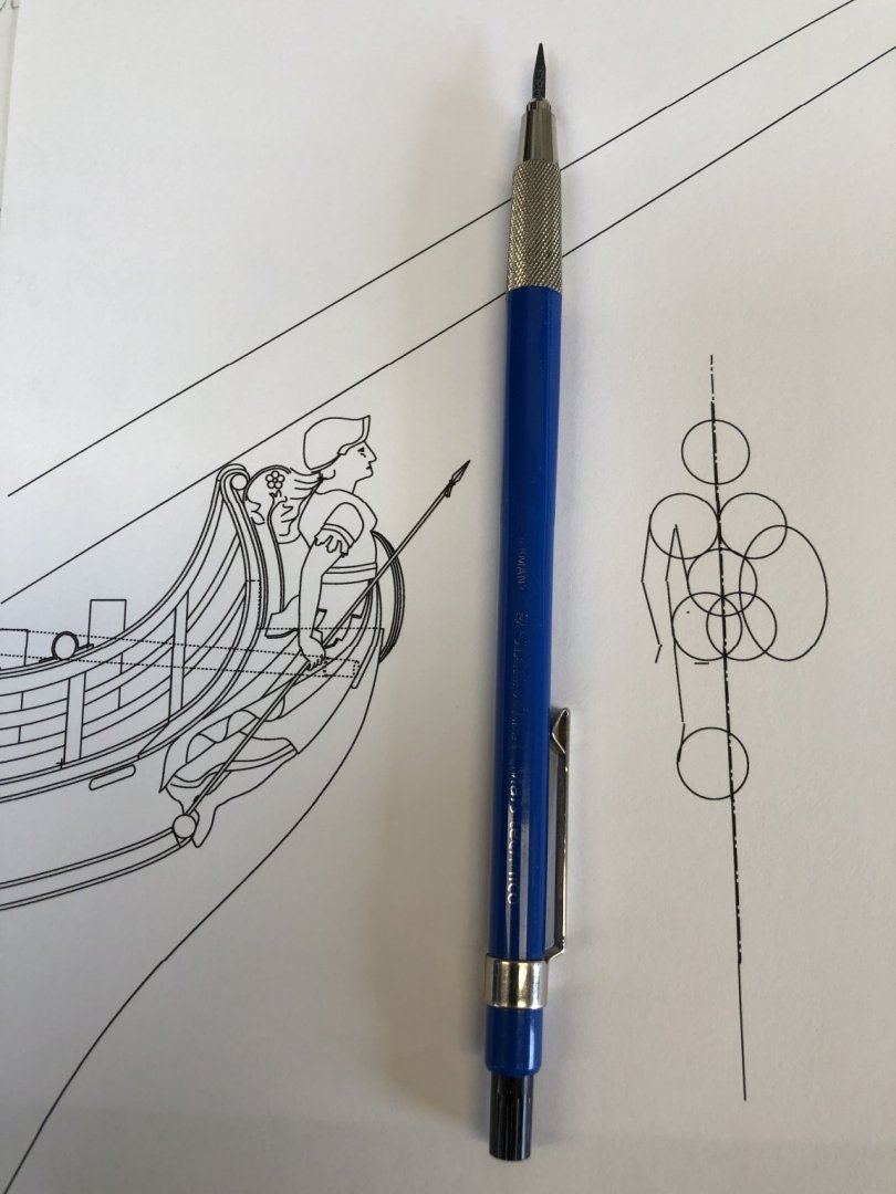
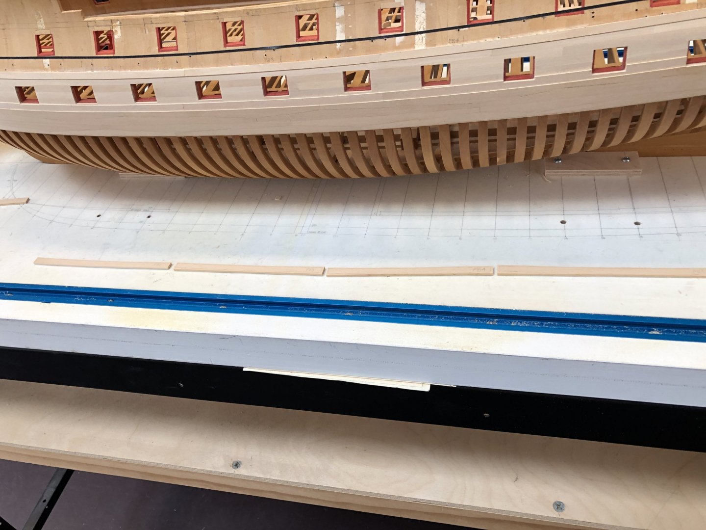
Some other life activities got in the way of the model for a while. I am grabbing a few moments in the shop from time to time, and here is an update. Planking continues, and I am refining how to do this as efficiently as possible both for time and for materials consumed. I started ripping planks off a blank wide enough for later spiling of the individual planks. But this turned out to waste a lot of wood that was initially cut too wide for the final plank. So I then made manila file templates for each plank in the second strake of the channel wales: Then I laid these out on the blank port and starboard of each piece next to each other to avoid different curves wasting more wood (I will flip the starboard ones when fitting): These are now cut out on a scroll saw, and ready for sanding to size and fitting: Meanwhile, I have been thinking about the carvings on the head and stern, since I took the time to draw them out earlier. They are going to be small, particularly on the stern, as seen by the mechanical pencil on the drawings: Will I be able to make them look anything like the original? Daunting! All for now, Mark

-
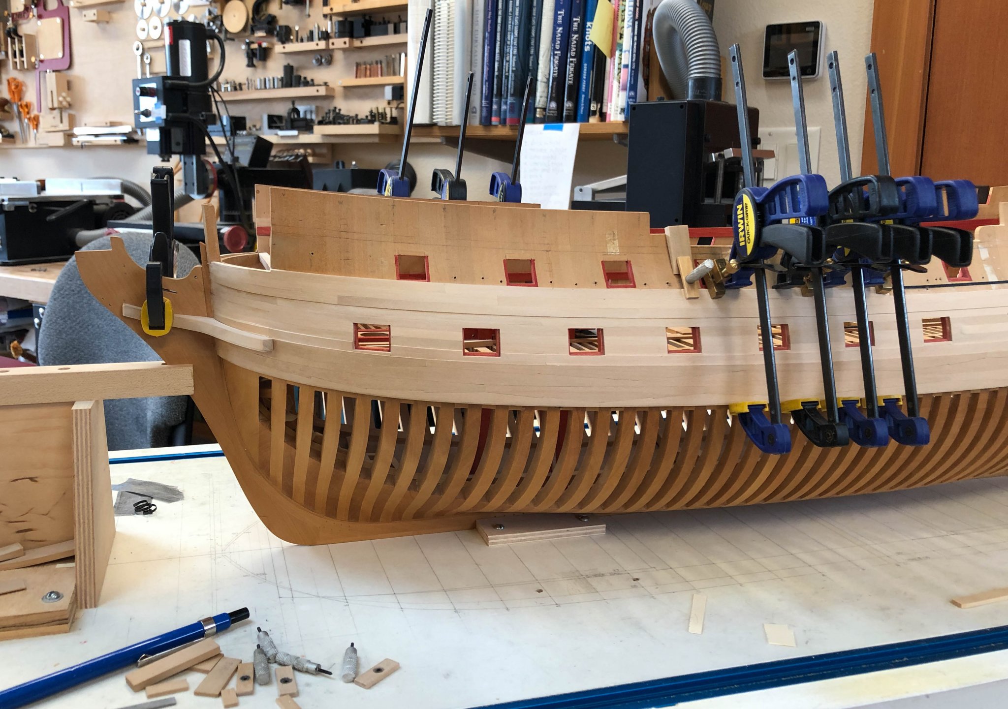
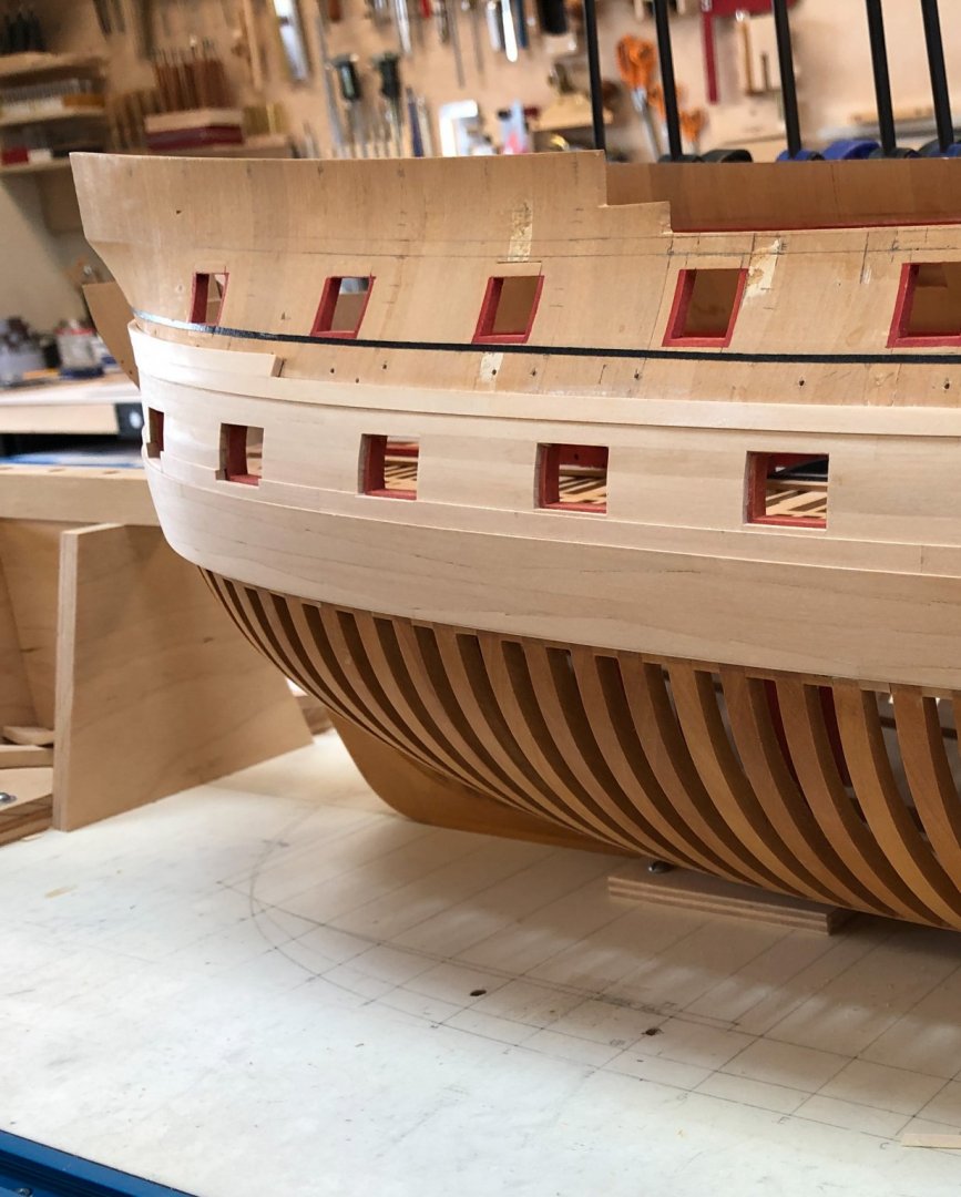
shipman, was that the large hall of models in the National Maritime Museum before the awful renovation? And was the Longridge model in that hall? That NMM hall was one the greatest places I ever remember experiencing; you needed days to look at it all. What a tragedy for all of us it is gone. Here is a photo of the first strake of the channel wale complete, on the port side. You can see how much the tumblehome straightens up towards the stern (compare the angle of the ports to the angle of the door to the quarter gallery) and the strake reverses its curve compared to the main wale below, causing the notable variation in plank widths. Mark
-
Wow, thanks, Mark. At least temporarily, my planking is staying in place better than that. Only time will tell, of course! Longridge was always my gold standard, sobering to see how time might treat our efforts. The surface also looks somewhat rough in the photo, and I recall him writing about polishing the finish. druxey, any idea what kind of glue Longridge had available to him at the time? Mark
-
Thanks, Gary, your Alfred project has always inspired me to keep going and do it well; I will work on regaining my patience! Greg and druxey, very interesting observation on Longridge's plank separation. If he really did use constant width blanks, he must have really cranked some of those into place. And even then, I would assume that he would have faired the upper edge after installation of each strake, just to get them down to the right width at various places on the hull. druxey, did Longridge's Victory move from place to place with lack of environmental control? I recall him writing about storing it in a seaside fortification during the war to avoid bombs, and finding a fine mould on the surface when he recovered it after the war. That could not have been good for it, to start! Mark
-
There was a time I thought I should have done a three decker, and now grateful I did not. I increasingly look wistfully at the frigates, sloops, etc. with one deck. I might have had a better chance of finishing one of those in my lifetime! I did not appreciate how dreary the planking becomes after a while. I recall reading Longridge's book on the Victory many years ago, which seemed to suggest that you just rip out planks of the correct thickness and width, and then bend them into place. I don't see how he did that. My hull requires spiling every single plank and custom fitting it. Because of the varying tumblehome, the planks vary in width along the total length of a strake; no way a single width blank could ever work. Oh, well, plug along--or maybe plank along.... Mark
-
Thanks, druxey and Gary. I was having so much fun planking without dealing with gunports, and now here they are back again!🙂 Mark
-
With the head drawing now behind me, I am carrying on with planking the channel wales. I just hit my first gunport for the upper deck, and realized I don't know if the stop or rebate for the upper gun ports are the same as for the gundeck ports--i.e., 3". Has anyone seen a specification for the rebates reducing in width as we progress up from the gundeck through the upper deck to the quarterdeck? Mark
-
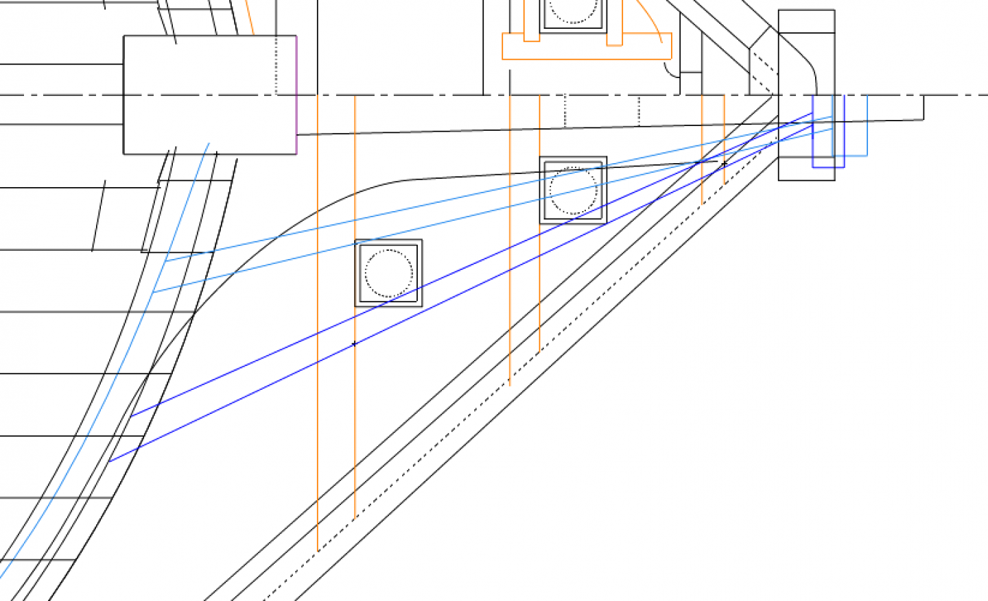
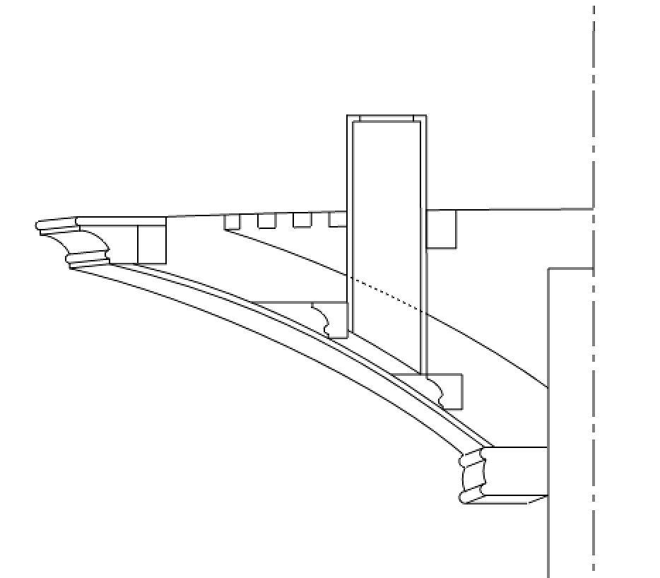
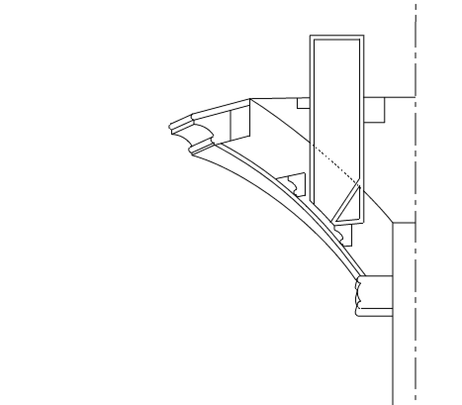
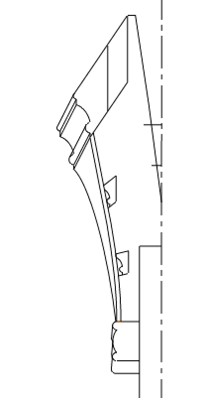
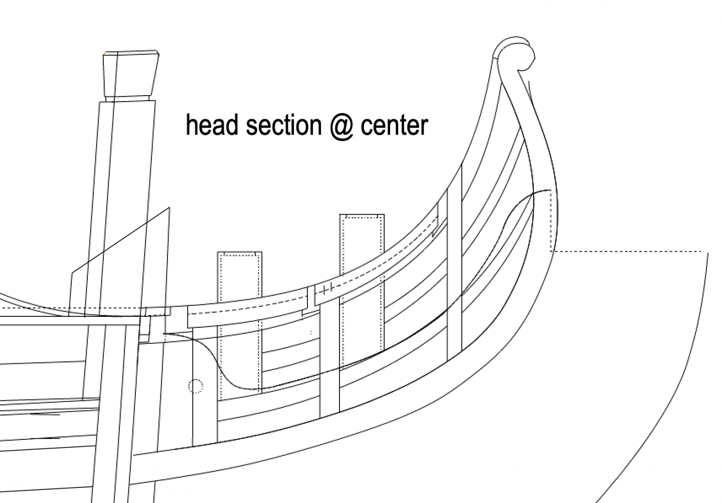
Thanks, Marc, that is a delightful moulding detail. It is still amazing to me how almost every craftsma-before architectural Modernism took over after the Second World War--knew how to execute traditional Classical mouldings. Almost a lost art now. I needed to do a fair amount of refining on the head structure. The line and angle of the main rail is a given, as is the line and angle of the top of the upper cheek. The head timbers have to align with these top and bottom, but the curve in between is somewhat flexible. I discovered, once I projected up the locations of the middle and lower rail, that these curves had to move in an out a bit to align properly. I had to adjust the angle of the rails in plan a few times before everything line up in all three dimensions. I also learned from David Antscherl's Fully Framed Model book (vol. II, p, 227) that the slots cut into the head timbers are not parallel to the ground, even though the tops and bottoms of the rails are parallel to the ground. This is because the inner face is rising faster than the outer face when it cuts at an angle across the head timber. Very hard to visualize at first, but I confirmed this is indeed the case. Here are the three timber heads: And as you can see in the second one, the discharge tube does fall onto the lower rail. The only two sanitary ideas I can imagine, are Mark P.'s slanting tube, or here a sloping shelf. I will go for the sloping shelf for now... And here is a cross section just to the port of center, showing some of the construction. I think I will have to refine the upper edge of knee to align with the lower rail. Those two lines should be more fair to each other I am thinking. I think I am tired of working on the head drawings, back to planking! Mark