SJSoane
-
Posts
1,650 -
Joined
-
Last visited
Content Type
Profiles
Forums
Gallery
Events
Everything posted by SJSoane
-
 Thanks, Siggi, I just drew up two different versions of the window, one with glass and a wood panel, the other with just the wood panel. Here is with the glass: And here is with only a wood panel: The construction certainly is simplified with just the wood panel, particularly since my glass sheets in the model are thicker than they should be to scale. In the examples you have seen, was the black paint glossy, or Matt? I can try some experiments with glass, wood and paint to see what makes sense for the model. Mark
-
Hi druxey, Just saw your post after I posted mine. Thanks for the observation of the actual models. I am likely to continue with that tradition, because I think it would just look better! See, now I am thinking like an 18th century shipwright! Mark
-
Hi Gaetan and Jason, Thanks, this is additional confirmation for what I now see would have been a clearly common practice. I remember reading about false windows on buildings in England, so there would have been a cultural precedent. Interesting in the photo Jason provided above that the fore and aft windows were also false, except for what appears to be one upper sash of one window. The captain must have desired exceptional privacy when docked! Good point about whether there was glass on the outside of the false window paneling. Maybe that was just a modeler's conceit, because it would have been expensive and vulnerable to provide glass for no functional purpose in the real ship. But then there were a lot of expensive, vulnerable and functionally useless things on these ships like the carvings and friezes. Maybe aesthetics counted far more than we assume today. Mark
-
Hi druxey, Ahah, that link to the photos of the Bellona model at the NMM clearly shows in the black and white photo that the end windows are blind. I never noticed that before. Do you recall if you modeled the wood paneling right up flush to the glass, or is there a gap between glass and paneling? Mark
-
Exquisite machining, craftsmanship. I think I need a more powerful magnifying visor; you are working at exceptionally small tolerances! Mark
-
Spectacular! Gorgeous work. A great team. Mark
-
Hi Marc and druxey, So the quarter gallery window at the stern is a dummy? Does that mean it still has glass but the glass is backed by a panel of wood? Or the internal side of the window is painted a color? It seems it would have glass because the reflectivity in photos of models seems to be the same across all the windows. Mark
-
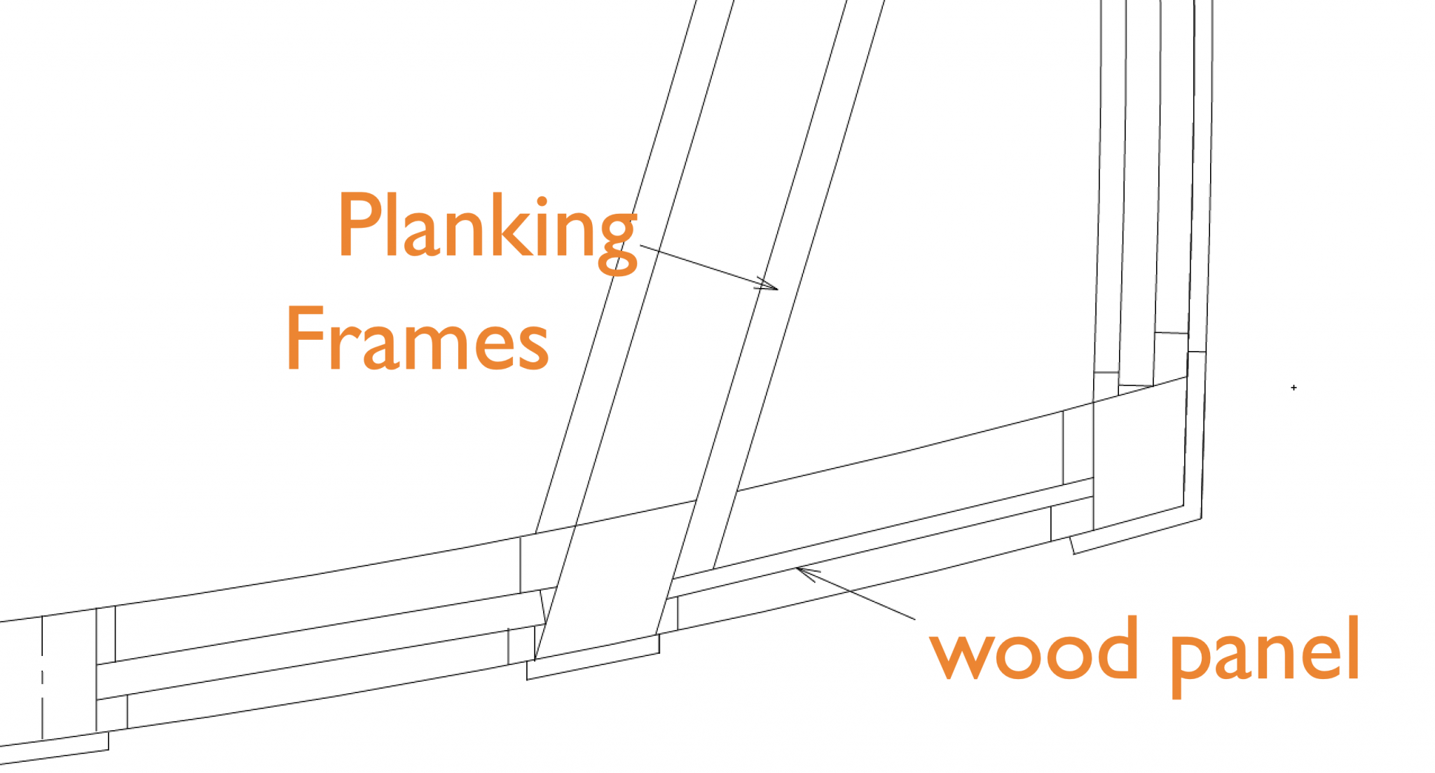
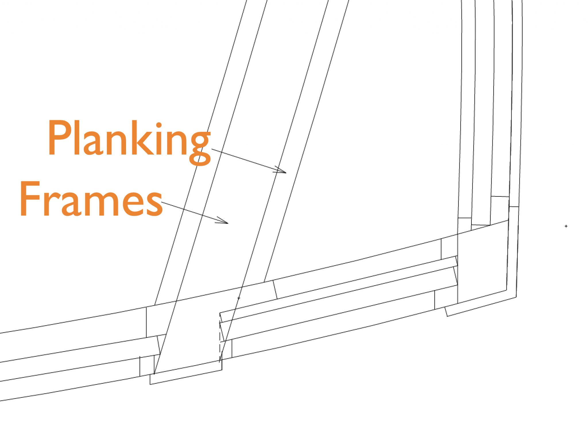
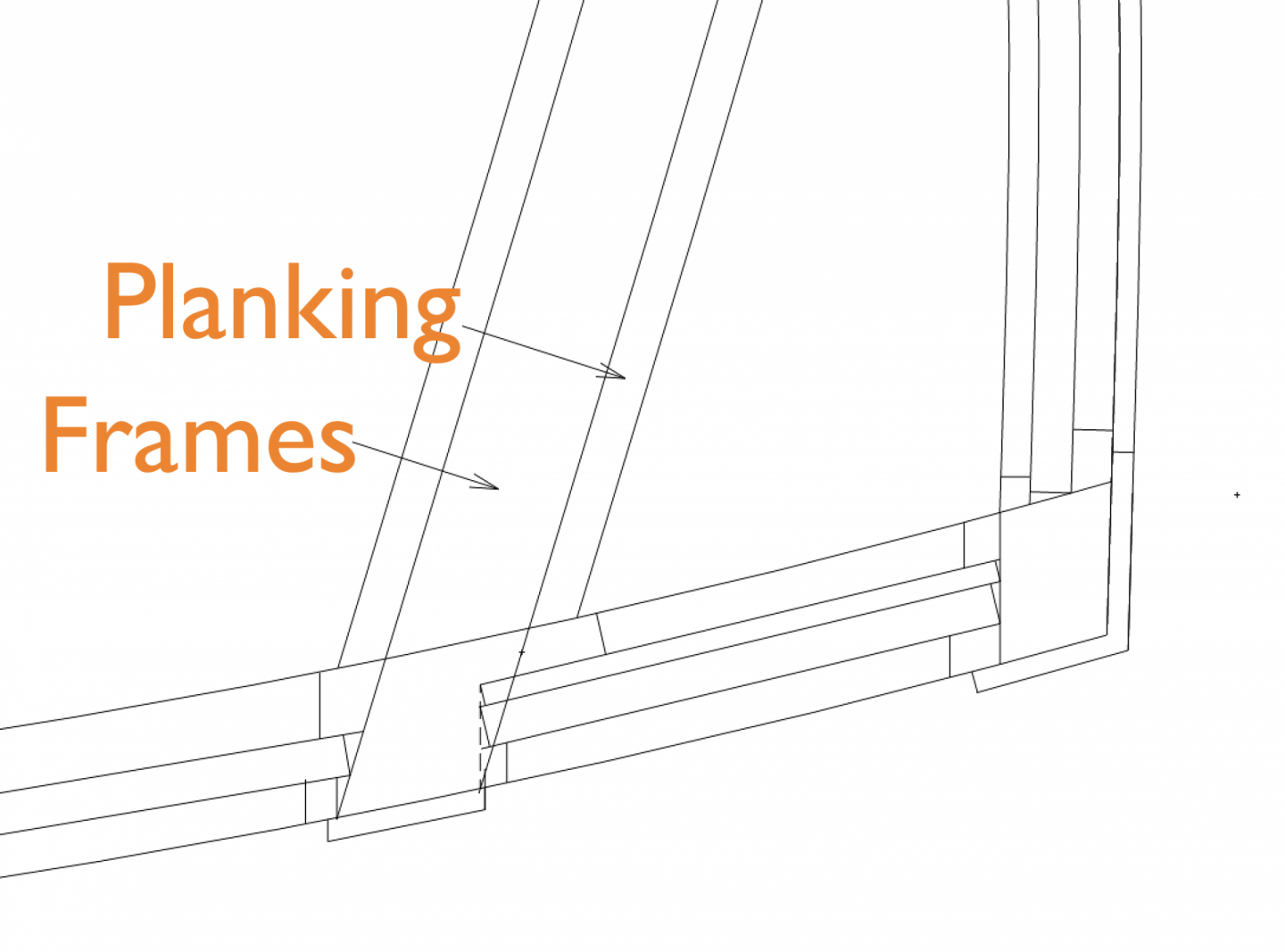
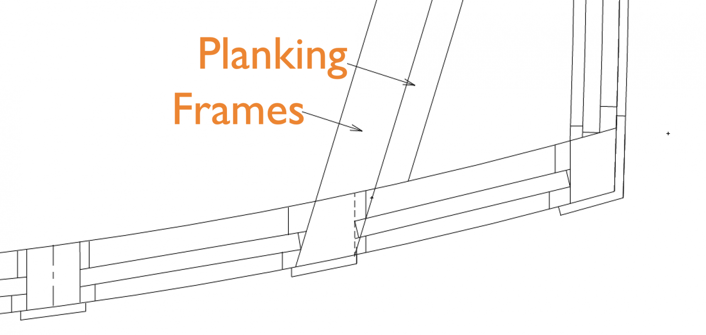
Thanks, Borden, for your support. One of the greatest pleasures of working on this ship is viewing its beautiful lines. It is endlessly mesmerizing to look at the flow of the curves in three dimensions. While waiting for some more planks to steam, I looked a little more carefully at what happens at the stern windows in relation to the external planking. In order to keep the windows all the same width on the outside, the window into the quarter gallery really starts to intrude into the hull frame at the frame's aft most edge. It looks to me like the frame needs to be cut away to the dotted line I am showing below, to leave room for the glass and its inboard stop. And the planking, which at this point is the channel wale, is 5 1/2" thick. It seems it needs to stop short of the window frame as I have shown here. That means there is a gap in the quarter gallery wall, where the glass seems to disappear into the wall behind the planking. Perhaps the channel wale needs to be thinned down more at its aft most end, maybe aft of the door into the quarter gallery? This seems a pretty awkward detail. I have not been able to find any drawings or photos that show this detail. Is anyone aware of how this detail is handled, other than what I am showing here? Best wishes, Mark
-
Thanks so much, Marc and Tony, for your kind comments. As you know, it is kind of a lonely process building a ship model; feedback definitely helps keep me focused! Mark
-
Thanks, druxey. I have a very nice Frankenstein's monster seam at the front of my forehead. I don't really care anymore about what it looks like, but it kept me from wearing my magnifying visor until the stitches came out!
-
Matiz, outstanding joinery. You make it look so easy, and I know it is so difficult to keep such close tolerances and fit. Mark
-
Gaetan, those are remarkable joints in the beams, with dovetails across the face of the mating surfaces. I am not aware of a joint like that in British ships; another French innovation that makes a lot of sense. What brand is that little razor saw with the straight red handle in posting #668, the fourth picture down? It looks very useful. Mark
-
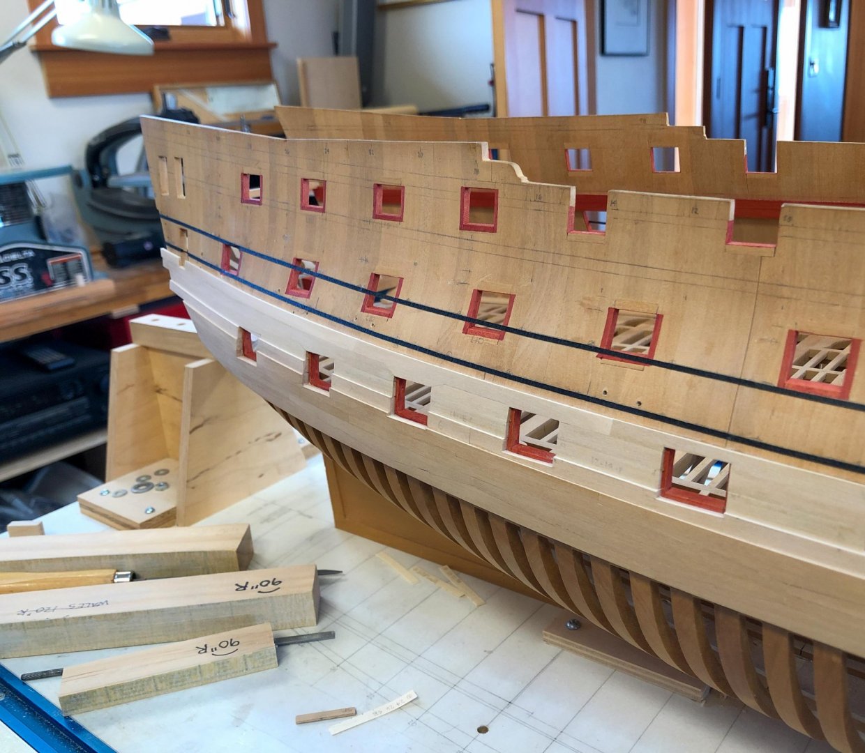
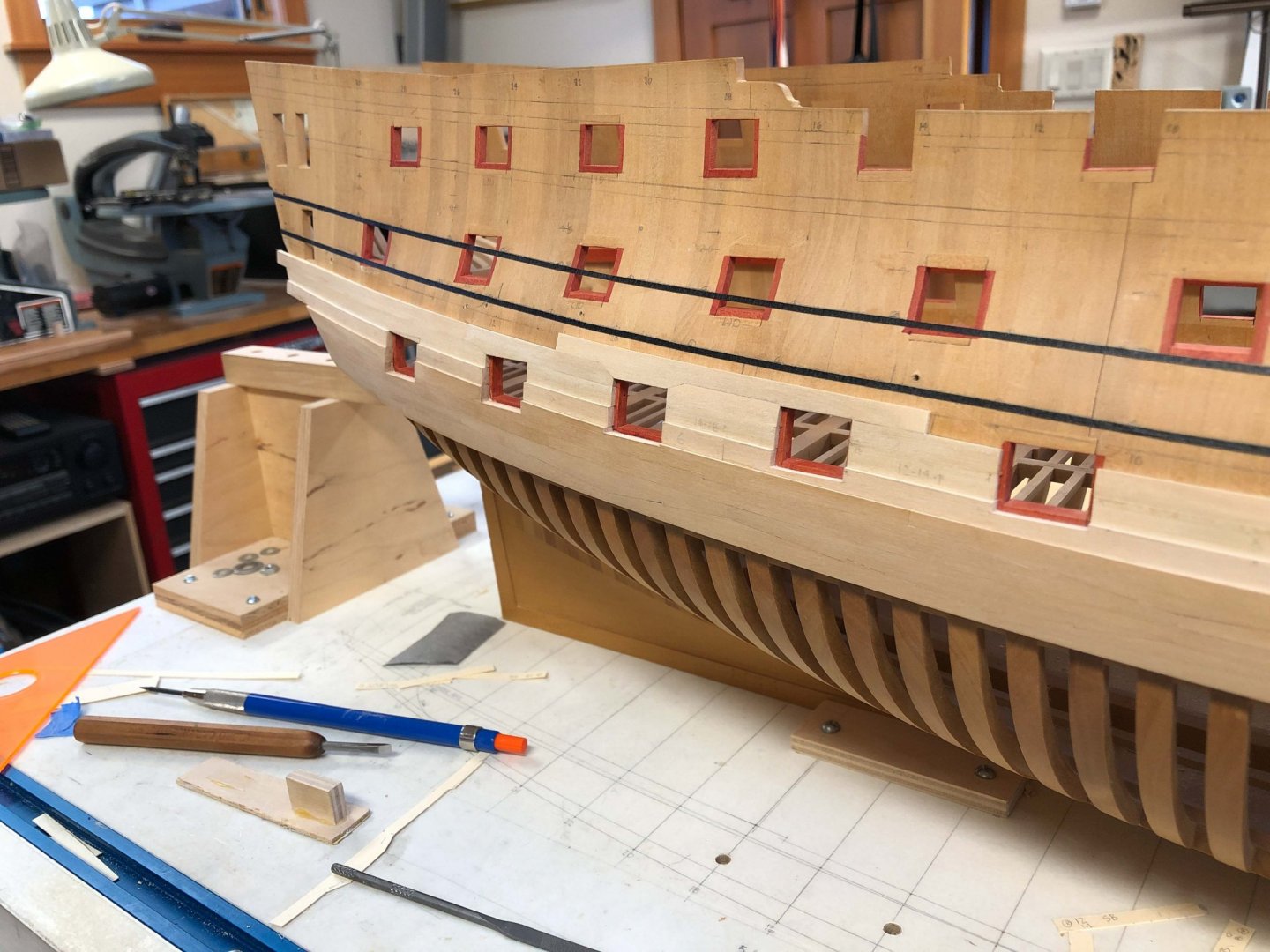
I had to take off time from the ship for some overdue dermatology treatments. Living for so many years in Denver at 5280 feet altitude (1609 meters) put my skin way too close to the sun. Now I live at a measly 2930 feet (892 meters) I can hardly see the sun.😎 So back in the shop, I have finished up one more strake of 4" planking above the main wales. In this photo you can see just how much the planking forms an S curve at the stern, as the bulging tumblehome flows into the straight edge at the stern structure. You can see from the pencil marks on the planking that this is yet to be sanded on the surface, and yet to have sawdust cleared out of the corners of the ports. It also looks a little raw white. The nice golden patina seen on the rest of the hull will come after 5-6 months of exposure to the air once it is finish sanded. And once the finish is applied, it should eventually look the color of the frames below the wales. The wale will of course be painted black. Just one more strake before the channel Wales between the black lines! Mark
-
Naval novels like O'Brian conjure up dramatic images of these times, but nothing like actual documents from the time to make this period very real! Mark
-
Looking very nice! Mark
-
Alan, I wish I had known about that Helicoil when I dealt with this many years ago.... Nice contribution! Mark
-
Alan, very impressive the list of articles you read. I hope you are planning on writing a book! Mark
-
Gaetan, beautiful craftsmanship with all of those precise dovetails and mortises on the beams. An inspiration! Mark
-
Hi Grant, I had a chance to look at your Da Vinci Flying machine and the Chris Craft Runabout. Very impressive craftsmanship, and use of formers and jigs. A lot to learn from you in those posts! Mark
-
Michael, I just caught up on your latest progress. Astonishing what you can do with metal. A masterpiece! Mark
-
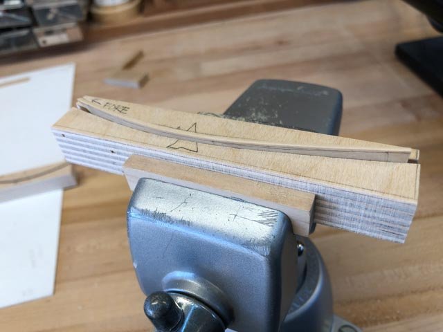
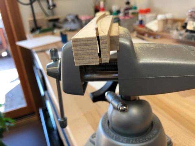
Alas, life gets in the way of the shipyard. Not much progress to date, due to other things going on. But I did take the good advice from Grant, and I made cauls for the planks at the bow. These needed tiny 4" spacers at the bottom of the caul, to hold the jaws parallel when clamped onto the 4" plank. I made two set of cauls, one for the foremost part of the bow where the planks hit the stem, and then one a little further aft. These are two different curves. I just choose the one that fits the plank at hand best. The planks are springy enough to accommodate to the caul, even if the curve is not exactly right. I don't know why I did not do this when I first started planking, it works so well to hold the planks firmly for fine shaping. A classic woodworking concept; hold the piece firmly on the bench so your hands are free to manage the tool. No more filed finger ends, or tired hand muscles holding onto the planks. A joy to use. Thanks so much, Grant, for the idea! Mark
-
Alan, the rudder looks great! Mark
-
Thanks so much Mike and druxey. I confess, when I started I thought this was going to be fairly straightforward, made complex only by having to bevel the edges for tight joints. Maybe I got that idea from Longridge's book on the Victory, or maybe from reading about modelers cutting long strips to a set dimension. But you both knew better, and now do I! This is much more complex, requiring spiled edges and precise fitting. The planks are not even the same width at the stern as they are at the bow, even though the lines of planking on the sheer drawing are parallel segments of circles. I believe it is the varying degree of tumblehome that stretches and contracts the space between the parallel segments in the third dimension, making the planks between vary their widths. And I thought I was about to start sprinting on this project!😊 Mike, I decided not to highlight the seams between the planks, partly because I could not obtain consistent results in my tests, and mainly because I like the look of the 18th century models like the second Bellona model, where the seams are not highlighted but variations in wood color hint at the planks. I think this is what a viewer would see standing far enough from a real ship to be the same as looking at the entire model in our cone of vision. Of course, this also means that my painstaking craftsmanship doesn't show up except in extremely close observation! Mark
-
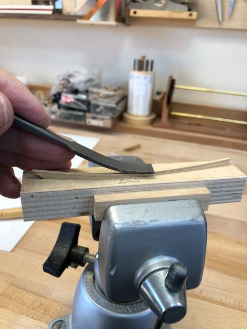
A little slow in the shop this week. Here is the complex plank installed. This required a great deal of finding high spots by holding artist transfer paper between the joints at various places, then filing down with a very fine flat Swiss file, then checking again. When I felt my patience disappearing, I would leave it and go do something else. So it took me a while. Mark
-
Astonishing detail and craftsmanship. You set the highest standard! Mark