SJSoane
-
Posts
1,655 -
Joined
-
Last visited
Content Type
Profiles
Forums
Gallery
Events
Everything posted by SJSoane
-
 This certainly looks logical and craftsman-like. Thanks, Siggi, druxey and Mark for exploring this fascinating detail. Mark
 -
Thanks, druxey and Greg. Nothing like a few setbacks to build greater resolve! Greg, I seriously thought about adding CNC to my Sherline lathe and mill; but when I looked into it on their website, I came away thinking it is not going to work well for me. I may be wrong, and would love to be corrected by someone, but it looks like Sherline has developed a system that works best with their own included computer and software. I did not see how Fusion 360 would talk to it, nor how I would be able to use my own Apple computer. Someone handy with computer hardware tweaks might figure this out, but that is definitely not one of my skills Does anyone have experience with Sherline's CNC setup? In particular, with a Mac? I'll bet the computer doesn't have to write down the X and Y coordinates on a slip of paper so it doesn't get confused.... Best wishes, Mark
-
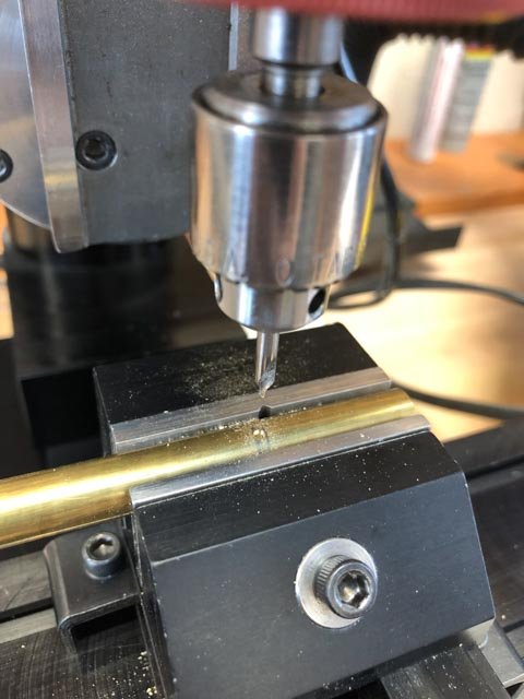
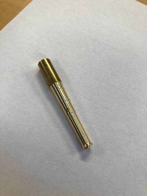
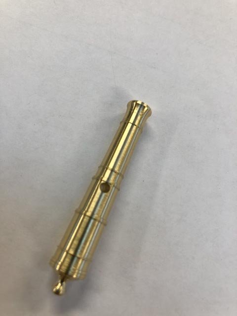
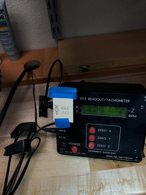
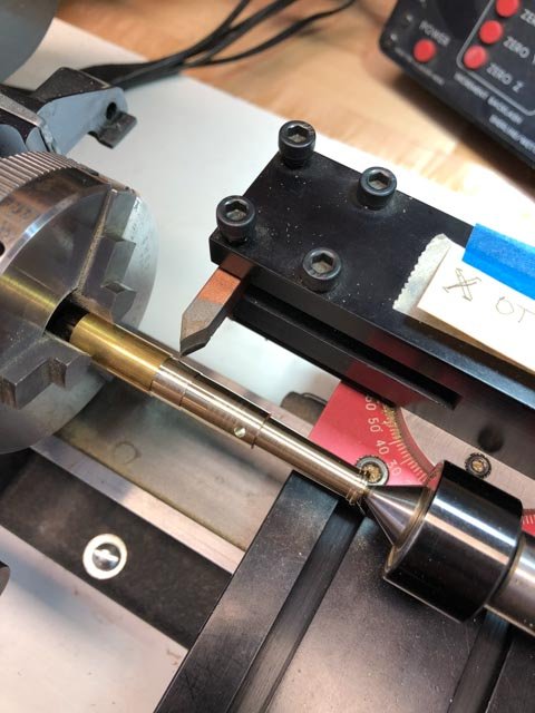
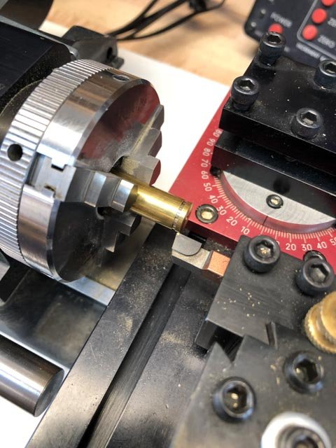
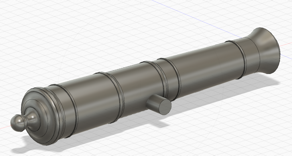
Hi everyone, It has been a long journey figuring out how to make the cannon. The efforts at pattern turning failed miserably. I used an old Vanda-Lay pattern tool for the Sherline, but I could not keep it from deflecting, and the cuts were quite ragged. Probably operator error, but not worth pursuing I decided. I temporarily lost heart, thinking about the long uphill climb making 74 guns, and I looked for ways that I could have them made for me. But 3-d printing was way, way too expensive, and I did not find a source that could provide the level of quality I hoped for. I also explored the idea of having them CNC lathed, but could not find a willing machinist. All of these failures were just as well, because this focused my attention again on how to do these myself. Here is a summary of where I am so far. I have determined to turn masters in brass, then cast in pewter. I think my previous casting problems were caused by a strange pewter that I had purchased from a jewelry supply store many years ago, which needed high heat and this destroyed my moulds too quickly. I have ordered low temp pewter from MicroMark, and I hope this will work better. To make the masters, I first drew the cannon in Fusion 360 (a great program, I am discovering, and free for hobbyists). I was able to create a number of instruction sheets, one for each stage of cutting, so I could dial in the dimensions with great accuracy for the fine mouldings. I used the Sherline compound angle slide for the taper cuts, which does not work with my digital displays. So I had to calculate how many turns of the dial for each manual move. I found that my attention wandered when dialing in all of these X and Y dimensions, leading to ruining parts well into the process. So I wrote down the next X and Y moves on a card taped to my digital readout. This saved me from a lot of silly errors once I got used to it. I also messed up overall dimensions at one point, placing the trunnion hole too close to the muzzle (the cannon below with the turned cascable shows this error). I then figured out how to measure from a temporary trunnion in its drilled hole to the hind side of the base ring, which became a fixed measuring point for subsequent operations. The cascable was cut while still using the tailstock for stability. I used the cut-off tool for cuts straight into the metal, and then files to shape the ogee and the button neck. A little scary, thinning down so much while still between centers, and also holding needle files so close to the spinning chuck. But no accidents yet. On to the other three cannon masters.... Happy new year to all! Mark


-
Longridge's Midget Universal Woodworking Machine
SJSoane replied to SJSoane's topic in Modeling tools and Workshop Equipment
Thanks, Bob, you offer an insightful overview of how our world of modeling has been shaped by large societal and technological changes in the last 70 years. It is interesting to reflect on how the these changes could both kill an earlier industry (Roemer), and help a more recent one, (Byrnes, et al). Mark -
HMS Pandora 1779 in 3D
SJSoane replied to ppddry's topic in CAD and 3D Modelling/Drafting Plans with Software
Beautiful model! Mark -
Thanks, Siggi and everyone else, this was a very interesting discussion! David Antscherl's books on the Fully Framed model show an additional port liner added to the sides of the frames, to create the rabbet. Mark P's descriptions seem to suggest that the rabbets were cut into the face of the frames themselves, as Siggi's drawing show. Whichever it is, would the size of the port called for in the contracts and drawings be measured between the inner face of the linings, or between the ends of the outer planks? My own model made a decision for the latter many years ago, so I am already committed. But would be interesting to know. Mark
-
Hi everyone, If you read Nepean Longridge's classic book, The Anatomy of Nelson's Ships, you would have been intrigued by his description on page 49 of his beloved Midget Universal Woodworking Machine. He bemoaned the fact that it had stopped production before the war, and had reached out to the manufacturer. W.C. Roemer, to inquire if it might resume production. Roemer replied that he hoped to, if labor and material became available. But Longridge then noted that currency restrictions in Great Britain after the war would prevent purchasing this American made equipment anyway. I had never read of it anywhere else, so I assume Roemer was never able to start production again. Longridge stated that if ever his machine were destroyed, the very first thing he would do would be to make another one. I was always intrigued by Longridge's detailed description of this machine. I just discovered a photo of it, on a vintage machinery website. So if you were ever similarly intrigued, here it is: http://vintagemachinery.org/photoindex/detail.aspx?id=7623 I am very happy with my Byrnes Model Machine tools, which probably work better in many regards than this all-in-one tool. But it is fun to see this earlier effort at tools for model makers. Mark
- 5 replies
-
- 12
-

-
Hi Doris, I am just catching up with your postings. The craftsmanship is as usual the best ever. I particularly enjoy this time your lighting, and the scene from your living room that looks like a ship is on fire somewhere in the distance. Very evocative! Mark
- 1,035 replies
-
- 7
-
-
- royal katherine
- ship of the line
- (and 1 more)
-
Hi Siggi, Sorry to hear about your health issues. Let's hope for the best for the new year. I have been assuming that the port lids are as druxey explained, and as are seen in the Bellona model. I take the Bellona model as contemporary first hand source, since it is unlikely the model got rebuilt in this area after it was finished in the 18th century. But it is interesting that the Victory shows gunport lids with no rabbet; they appear to be the thickness of the exterior planking only. I wonder what they were looking at when they rebuilt this? The sides also appear to be perpendicular to the fronts, not tapered. The lower edge tapers because of the great angle of the tumblehome sides, it looks to me. Mark
-
Hi Peter, I look forward to learning what you find out about using Sculpt and T-Splines. A whole new world to me. I apologize for not being clearer in my drawing. Let's assume the thick black line in my drawing is the top, outermost edge of the hull in 3 dimensions. The traditional way of locating that would be to go to each station line, and measure up in the Z direction on the X-Z plane the height of the line at that point above the base, top of keel usually. Then you would measure out from that point in the Y direction to find its distance away from the center line. I was hoping to do this at each station point and then link the points together with a spline to form the curve in three directions. I was then assuming I could use a series of lines like this to form the surfaces. This is how my ship was originally drafted, and so I assume this would be the right approach to using Fusion. The problem is that I cannot get Fusion to find the point I just drew on the X-Z plane when I turn to drawing on the X-Y plane. Nothing will click on it. I am wondering if I need to do this with solid bodies rather than just lines in space, so I can find them... Mark
-
Hi Peter, I don't understand how you managed to get the curve in three dimensions in Fusion. Looking at my drawing below, imagine measuring up along a station line in the X-Z plane, then measure out in the Y plane to locate a point on the thick black curve. I have not seen how to switch from drawing in the X-Z plane to drawing on an X-Y plane at right angles, and selecting where the first point on the X-Z plane is located. How did you do this? I could not see how you used the "project/include" tool to find the intersection. Best wishes, Mark

-
Wayne, that makes a lot of sense. I look forward to seeing how it works for Peter's hull. I am learning while watching! There is a Fusion tutorial online that shows how they constructed a curvy plastic housing for a reciprocal saw. It shows how they try to line up the contour lines to be even all around the form, as you suggest, and they are able to add in additional points as needed to do so at tight curves. Mark
-
Alan You are getting the hang of this! It becomes increasingly clear that this is not nearly as simple as just sending in an STL file. There is a major art to this, just like the art of understanding any other tools like traditional lathes. Mark
- 125 replies
-
- 2
-
-
- 9 pound naval cannon
- 3d cannon barrel
- (and 1 more)
-
I look forward to seeing how you resolve this. I don't understand lofting yet. But I did discover that the construction planes can be resized by pulling at their corners. Admittedly, annoying that they keep growing in size by default.... Mark
-
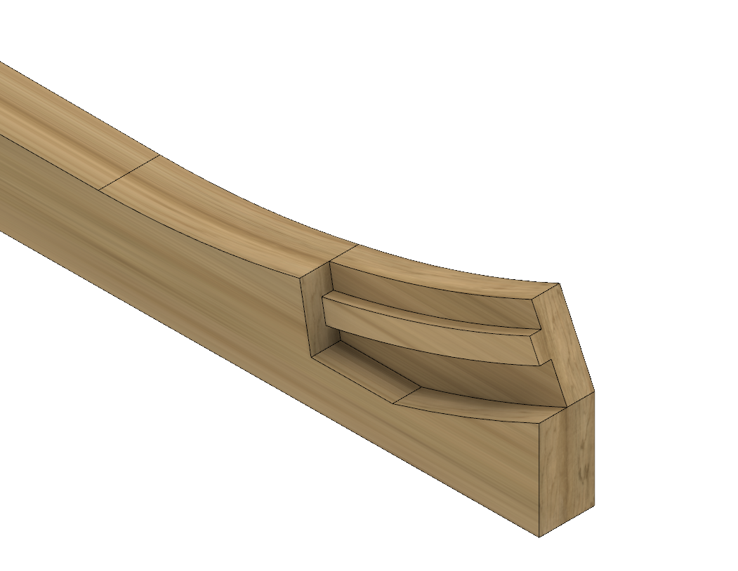
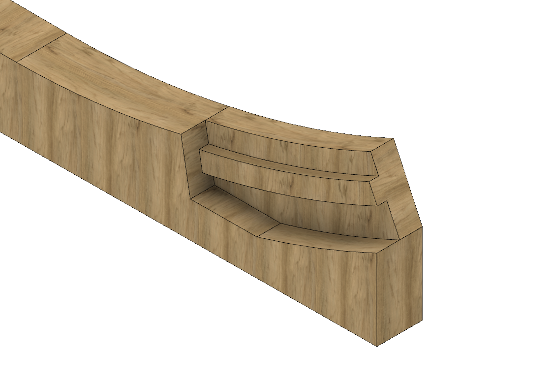
Hi Wayne I tried it and it worked! Thanks. Using that method you can choose any axis to align the texture to. The interesting thing about drawing the boxing joint is that I found out how to shape curved surfaces in Fusion. I drew the taper of the keel in plan, and then extruded it down to the keel's thickness. And then I extruded it up above the Top of Keel line to the top of the boxing joint, to provide enough material to include the curved up surface. I then drew a box in elevation above the Top of Keel whose lower edge is the shape of the upper keel surface, extruded it sideways, and then used it to trim the keel. Really easy. I imagine this can be used to shape transoms that curve in both directions, etc. Mark

-
I have been playing with Fusion 360 off and on, once I discovered that it is indeed free for hobbyists. I need to do some additional drafting for higher decks on my Bellona project, and thought I might use this to learn a new skill at the same time. There is a big learning curve for someone coming from 2-D drafting, but it is very powerful, drawing in 3-D where views do not have to be projected one from the other. Here is the beginning of drawing the boxing on the keel for the Bellona. I haven't figured out how to orient the wood grain in the right direction. In my architecture software, there are separate textures for both horizontal and vertical surfaces in order to align the grain, but I haven't found this yet in Fusion... Mark

-
I just experimented with Fusion 360 after working with TurboCad Mac for a few years (the latest upgrade for TurboCad includes CAM, I understand; my version does not). Fusion is definitely more elegant and powerful. It is still not clear to me from the website that the free license is renewable, and so I am a little hesitant to invest a lot of time into creating models with this if it eventually goes away. It has extensive and free training videos. Mark
-
Hi Alan, I just sent a PM.
-
Hi Paul, Now that is an interesting idea. The highest quality one would cost $26.40, maybe an interesting investment to see how it could turn out. I have heard that the best still have slight lines where the layers are formed, but cleaning up just one for a master would not be as dreary as cleaning up 74! I will reflect on whether this gives me anything better than just manually turning a master on the lathe, as I did before. Mark
-
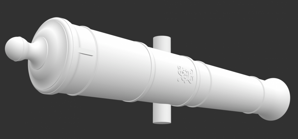
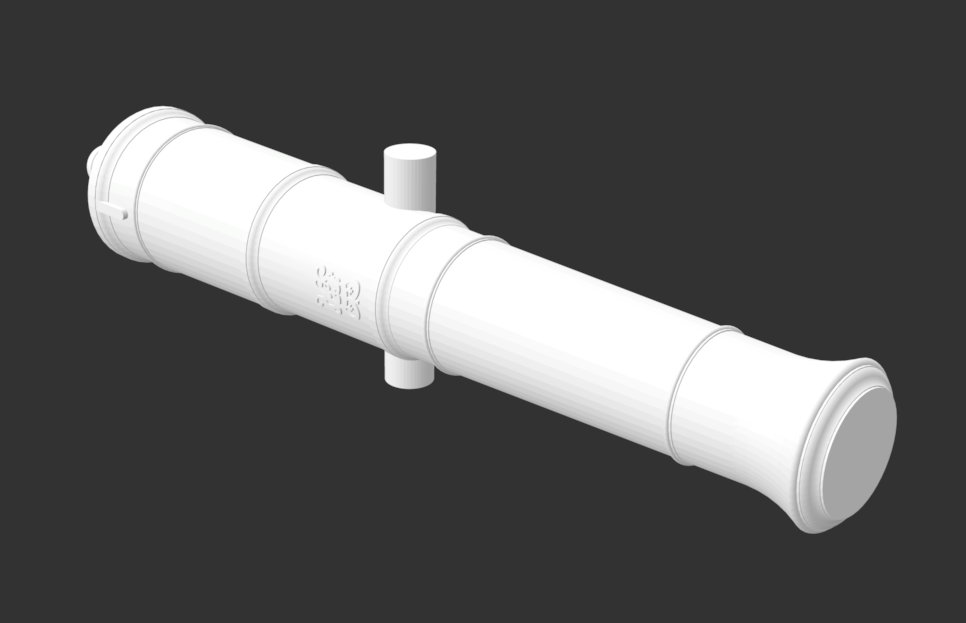
Thanks to the members on the CAD threads, I tried using Autodesk's Fusion 360 software to build a second version of the cannon, and it was very high quality; I also converted the earlier model with the insignia to the STL file type needed for 3-D printers, as shown below. But, it all came to nothing when I got the quote for 3-D printing at an online service. For the 74 guns it was going to be $556 for the lowest level of refinement, up to $1950 for the highest level of refinement. Way too much for a retirement budget, especially since I have been told that they will still show the layers as they build up. 3-D printing is no longer an option. On to other ideas. I realize that I was attracted to this because the digital model shows all of the wonderful, nuanced detail of the cannon itself, at a scale that looks real. But when this is shrunk down to 3/16" scale giving a 2" long cannon, most of the nuance disappears. I was disappointed to lose what I know should be there. Perhaps the best thing is to print out a large image of the digital cannon and pin it on the wall of my shop, to remind me what the model cannon represent! Mark


-
I played with Fusion this weekend, tried drawing my cannon project. It takes a little getting used to, but it did create a high quality model. Mark
-
a little more research on STL files today, and I found a much finer setting. I put all setting at 0 except normal deviation which I put small at 2.25. Putting this at 0 really messes it up, for reasons I don't understand. But this file size is 24 MB. I will have to find out the max resolution for the printing company tomorrow. Mark
-
I just came across this thread while posting another topic in this area. After struggling with some of the idiosyncrasies of TurboCad for Mac, I am intrigued by the videos for Fusion 360 a number of you have pointed to. But I don't find on the Autodesk website how much the subscription is after the free trial period, for hobby use. Has anyone subscribed to this, and can you tell me how much it costs you? Mark
-
Good suggestions. Here is a screen shot of the higher resolution file. Mark
-
Nice, Alan, I upped the surface deviation from 0 to 45. Much better. Thanks for the suggestion! It turned into a 2.2 MB file, so too big to show here. Mark 32 gun for export deviation surface to 45.stl