HOLIDAY DONATION DRIVE - SUPPORT MSW - DO YOUR PART TO KEEP THIS GREAT FORUM GOING! (83 donations so far out of 49,000 members - C'mon guys!)
×


SJSoane
-
Posts
1,649 -
Joined
-
Last visited
Content Type
Profiles
Forums
Gallery
Events
Everything posted by SJSoane
-
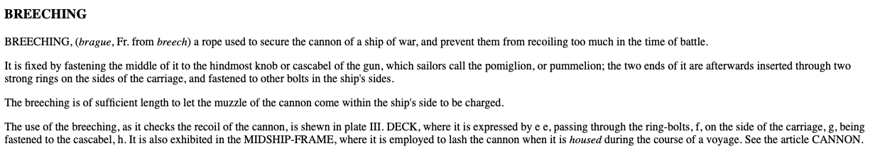
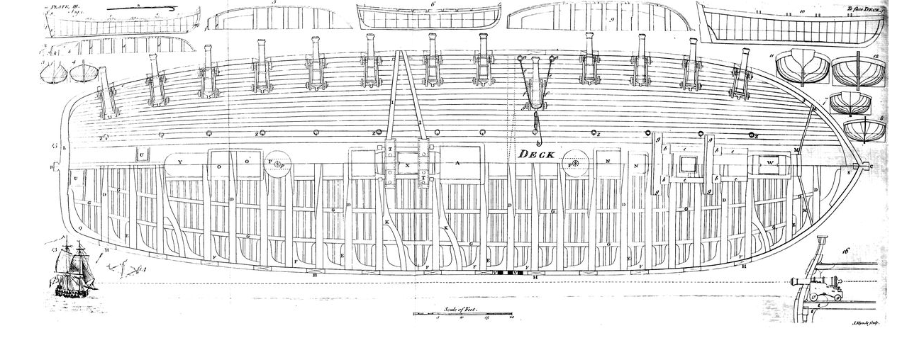
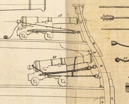
 Never hurts to read the text... Falconer does say that the breech rope is fastened to the button, which he calls the pumiglion or pummelion. But he also shows in figure III on the deck view to which this entry refers, that the breech rope simply sits on top of the button, and does not wrap around it. So, I think at this point I am going with it sitting on top, with a simple seizing or grommet with seizing, to the button. Does anyone have an image of how a grommet would be fastened to the breech rope? Come to think of it, the drawing of the deck below would also allow of a cut splice, although that is not quite what we see in the previous side view. Mark

-
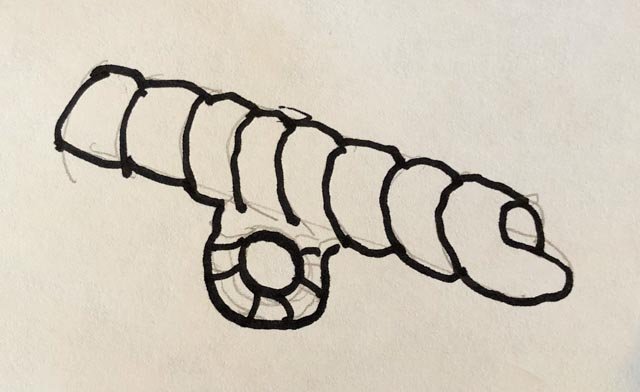
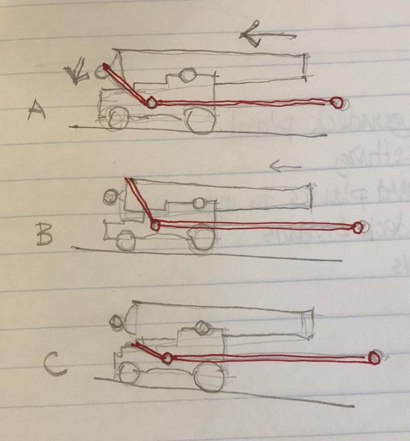
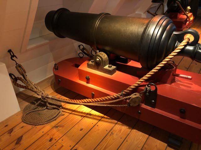
Now, on to the breech rope question. Apologies again to Siggi, druxey, Dan, Alan, Greg, Oldpaperone, Paul, Mark, Alex and Hubac's Historian, for not replying sooner to your all helpful comments. I will never forget my password when traveling again! I hope I will address all of your thoughts in the following: After looking at the various sources you have provided, it still looks like Falconer is closest to contemporary, unmodified material. I think it is showing the breech rope, even though it is too thin, because it reeves through the ring and eyebolt on the side of the gun carriage, just where many other sources show it. Even the carronnade shown below (from the Mariners Museum at Newport News, Virginia) shows the breech rope reeving through the ring and eyebolt on the side of the carriage. Now Falconer shows it lying over the top of the button, not wrapped around. This corresponds to the 1756 cross section of the Royal George, which Siggi showed us. At that scale of drawing, I doubt Falconer would have shown a seizing or not; he does not show the details of the fastening at the ring at the side of the ship, either. So maybe a seizing with a quick few turns around the button and breech rope? Or, as Paul suggests, a grommet seized to the breech rope and then to the button? Or, what if it were not seized at all? I studied this with a quick sketch below. The danger would be that the breech rope would accidentally slip up over the barrel (B), or down under (C), when the gun was pulled into the firing position and the breech rope was slack, or when it recoiled. But the sketch shows that neither situation would have been disastrous, because the ring and eyebolt fastening the breech rope to the sides of the carriage would have retained the gun in roughly the same way. A is the desired arrangement, showing how the breech rope pulls down on the button thanks to the side ring. But B does the same thing although the rope is sliding a bit on the top of the barrel. And C catches into the carriage itself. B and C might have allowed a greater distance of recoil, but not dramatically so. The ring on the side ensures that the forces acting along the line of retention is parallel to the deck and the gun recoil, no matter what happens to the breech rope at its inboard end. Oldpaperone, your drawings are very interesting, showing I think French guns? As I read them, there appears to be an additional hole in the side of the carriage, through which the breech rope is sometimes pulled. I don't believe there is a similar hole in the British carriages. Does anyone have further information about how that hole was used? Alex, it is interesting that Falconer's upper drawing shows the gun tackles tying up somehow to the button, with the breech rope removed. I confess I don't understand that at all. And a cut splice would be logical here; can we see the lower Falconer drawing as a cut splice? I should probably read through Falconer to see if he says anything about this. Thanks again, everyone, for your helpful comments and insights! Mark
-
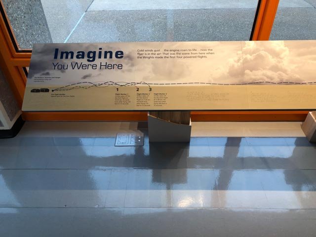
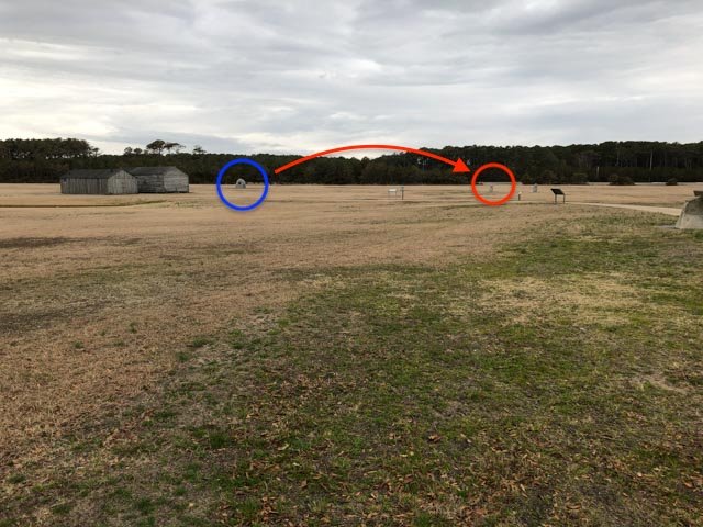
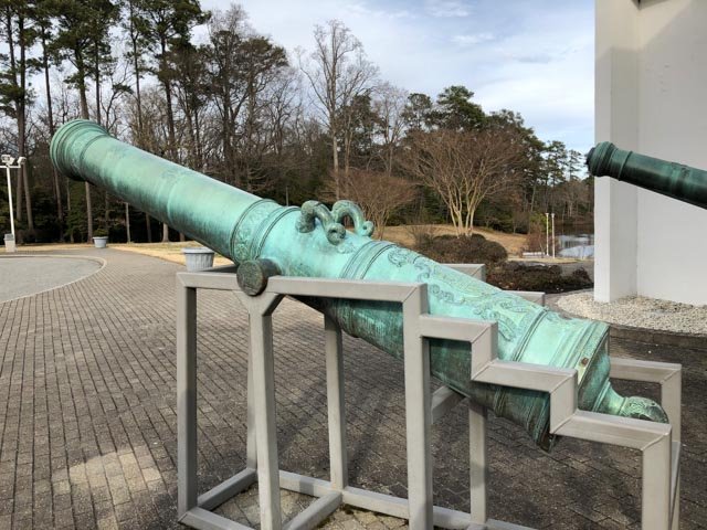
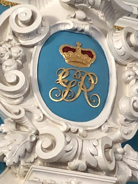
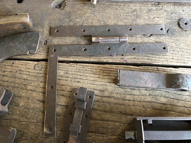
Twenty hours of traveling yesterday, with flight delays, and a ground blizzard driving 67 miles home from the airport. But a good trip. Here are some highlights before jumping into the Bellona gun question. 1. The location of the first powered man flight, at the Wright brothers museum at Kitty Hawk, North Carolina. The first flight took off at the blue circle, and landed at the red. Subsequent flights the same day went much further, as the plaque shows. 66 years later, we landed on the moon. 2. A 28# gun from the Mariners Museum at Newport News, Virginia. The gun is mid 18th century Spanish, except for the more elaborate detailing, it has much the same configuration as the British guns of the time. This museum has a large section on the Monitor and Merrimack (or Virginia as renamed by the Confederacy), which engaged in the Battle of Hampton Roads in 1862 nearby. The turret of the Monitor has been recovered, and is in restoration in this museum. 3. The Royal Cypher (George II) above a door at the Governor's Palace at Colonial Williamsburg, Virginia. This was when the British still owned Virginia, obviously. 4. A door hinge reproduction made by the apprentices at the blacksmith shop in Colonial Williamsburg. I believe these are the exact same design as those used on British 18th century ship partition doors. Now on to the Bellona gun question! Mark
-
Hi everyone, I apologize for not answering these recent many great comments. We traveled to Virginia and North Carolina this last week, and I forgot to take my password for the website; I could read the comments on my phone, but not post! I will address these in the morning, and also post a couple of interesting things I saw at the Mariner's Museum in Newport News, as well as at Colonial Williamsburg. Mark
-
The Falconer drawing is about the right time for the Bellona, and is contemporary. So a good guide here. I see the breech rope lying on top of the button, not wrapping around, and also more permanently seized around the bulwark eyebolt without a hook. It does seem very hit and miss whether that breech rope would stay in place in the heat of battle, when the gun is run out and the rope is slack. In a recoil, it looks like it could slip up over the top of the barrel, or even slide down and catch the carriage below, allowing an unexpectedly long recoil. Maybe just a light seizing run around the button that the Falconer drawing does not show? Mark
-
Alan, It looks great. Well done! Mark
- 125 replies
-
- 3
-

-
- 9 pound naval cannon
- 3d cannon barrel
- (and 1 more)
-
Looking great! Mark
-
Hi Mark and Alan, Interesting you would mention the end of the breech rope. I happened to see a secondary source drawing with the rope end forming an eye through the bulwarks eyebolt. That couldn't be right later in the century, because the rope would be permanently connected at both ends, with no way to remove the cannon with the breech rope rove through the cast ring on top of the button. Maybe when the rope just looped around the button this might be possible. But it does seem logical and efficient to have hooks at the ends. This would also alleviate the problems I mentioned earlier of how tightly the loop around the button would have to be seized or not. Sure wish I could see a drawing! And Mark, you are so right about why anyone would do a drawing at the time when everyone knew how it worked. Mark
-
Syren Rope Rocket
SJSoane replied to DelF's topic in Rope Making/Ropewalks's Commercial sources for ropewalk machines
Hi Chuck, Thanks, this is very helpful. I can only read in awe at a rope every 8 minutes, for a few hours in one go. An impressive goal I will aspire to! Mark- 42 replies
-
- 3
-
-
- ropewalk
- rope rocket
- (and 1 more)
-
Syren Rope Rocket
SJSoane replied to DelF's topic in Rope Making/Ropewalks's Commercial sources for ropewalk machines
Hi Chuck, I discovered that my tailstock wheel was beginning to wobble. When I pulled up the third rope to tension, it would be shorter than the other two already tied off because the wheel tipped. So, I have reset the setscrew, to pull the wheel a little tighter to the tailstock. And I really cranked it down on the bolt threads. That should help. When you tension the threads, do you pull out the stretchiness until it stretches no more, or do you push against each of the three threads in the middle of the span to test the different tensions? I was doing the latter, but think the former might be more consistent. Except pulling all of the tension out of those 3 strand ropes to make the 9 strand rope may be what pulled so hard on my tailstock wheel. Mark- 42 replies
-
- 2
-
-
- ropewalk
- rope rocket
- (and 1 more)
-
Thanks, Alan, this is very helpful. Thinking through a detail, it is nice to understand how the sailors would have viewed it, not just in practical, functional terms, but also in their sense of what is right. Also, it occurred to me that the later idea of running the rope through a ring cast in the cannon would most assuredly have anchored that breech rope to the cannon more thoroughly than just a seized turn around the button. Moving cannon must not have been a main priority with the detail. Unless someone comes up with a contemporary drawing, I am going with the seizing and turn as you and druxey have been suggesting. Thanks for your great observation! Mark
-
druxey, I would love to read that steampunk novel. Would the time traveller have focused on ships? Maybe the novel could answer all of these questions definitively, and in a few generations it would all pass down as absolute truth. No more historical worries for our successors. Plus, I want to see your design for the steampunk nautical outfit...😊 Mark
-
Syren Rope Rocket
SJSoane replied to DelF's topic in Rope Making/Ropewalks's Commercial sources for ropewalk machines
I tried turning ropes with three strands, then mounting these again in the ropewalk and turning them together with the drill running in the opposite direction. This makes a a Z, or right turned rope, which I believe would be a hawser? I did not get the tensions quite right, so there are some blips in it. It sets up powerful forces; trying to keep the headstock from unwinding was quite an experience! I had to unwind and then wind again, which probably did not help this rope much. As I measure things, Chuck's supplied thread is .017 in diameter. Three of these turn up to .032, or a factor of 1.9 times the original thread diameter. And three of those three, or 9 threads altogether, turn up to about .059", again a factor of 1.9 times the diameters of the ropes in the second stage. I have yet to try 3 threads in each eye, or 9 threads in one turning session. Will it be the same as turning the 9 threads in two sessions? It obviously changes the lay of S or Z. Mark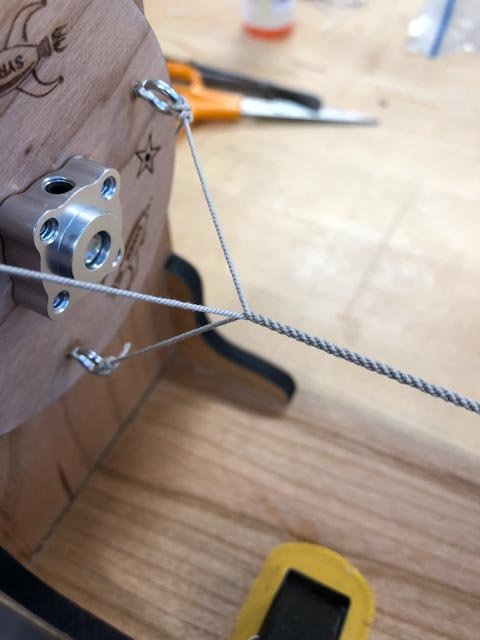
- 42 replies
-
- 8
-
-
- ropewalk
- rope rocket
- (and 1 more)
-
Pretty amazing, I cannot find any contemporary drawings showing how this breech rope is rigged. I found a photo of a section model of a 3 decker ca. 1760 in Brian Lavery's Ship of the Line vol. II, p. 156, and it shows the breech rope just draped over the top of the button, not even wrapped around. Of course, the rigging on that 18th century model could have been redone any number of times before its current state. I guess the 18th century draftsmen were not keen to draw draping ropes. I think the logical idea would be as Alan showed and druxy suggests with a seizing running in a vertical direction. This direction of seizing would be much easier to install, going with the lay of the ropes. But perhaps it would not have a seizing at all? It would be time consuming to move a cannon, first needing to cut the seizing to get the breech rope off the button. Or, would the breech ropes move with the cannon? Or is it seized loosely so that it can be slipped off the button? I can see why they cast a ring over the button towards the end of the century, because this earlier practice is not a very elegant way of retaining the gun, the more I look at it. Ah, where is that time machine when we need one! Mark
-
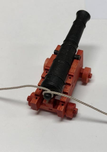
Hi Russ, Even as I looped the rope around the button in the photo above, I saw the need for some kind of seizing; otherwise, it would just fall off when the gun was pulled back to the side after firing. I will keep looking around. Thanks again for pointing this out; a new topic to research! Best wishes, Mark
-
Hull modeling with Blender
SJSoane replied to SardonicMeow's topic in CAD and 3D Modelling/Drafting Plans with Software
Fascinating. I enjoy seeing your experiments and problem solving. Mark -
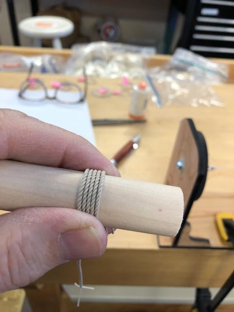
Hi Russ, thank you for your kind comments about the Bellona build. At the rate I am going, it will likely be the only ship model I will make in my lifetime (except for a kit when I was 16), so the journey itself is very much the point of it for me. I hope my journey and the Bellona build will finish at about the same time! Interesting question you ask about the breech ropes. I did a quick look at some resources this morning, and did not find anything about the direction of the seizing. I also saw a secondary source drawing showing the breech rope with a full wrap around the cascable button and no seizing (see below). Do you recall where you saw something, or do others have a source they could direct me to? Best wishes, Mark
-
druxey, Like this, with a better seizing? Mark

-
Thanks, Chuck, all credit to your great machine! I posted a few more comments on my first efforts (questions about how to tie off with even tension) at:
-
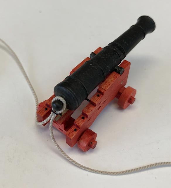
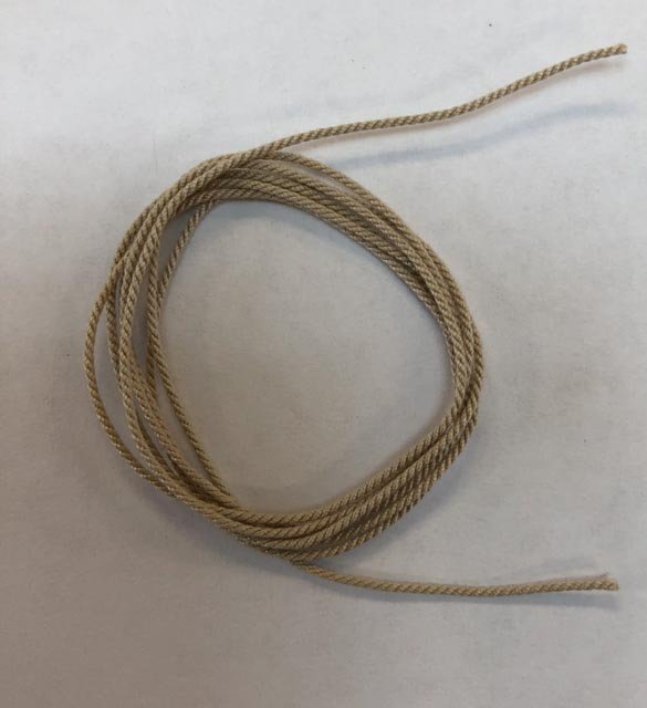
I have finally received the last supplies for casting (delivery is slow in rural areas, I have found). While waiting, I purchased Chuck's Rope Rocket ropewalk, and tried making the breech ropes for the 32# guns. I still have much experimentation to do with different threads and combinations, but the first efforts look pretty good. (this barrel was an old casting; but it was darkened and so shows the final effect). Mark
-
Syren Rope Rocket
SJSoane replied to DelF's topic in Rope Making/Ropewalks's Commercial sources for ropewalk machines
I am now a proud owner of a Syren Rope Rocket, and just made my first lines on it. I initially had a problem in the first stage of winding up the individual threads. They sometimes curled back on themselves in places, leading to little bumps in the finished line (see below). I am guessing that I was not holding the headstock tight enough to avoid sagging of the lines, or perhaps the tensions were not the same in the individual lines when I first tied them up. A subsequent effort, when I adjusted for these mistakes, worked much better (see below). A challenge for me is to tie the lines with the same tension. I am using a simple overhand loop at the headstock, to form a strong knot that can be slipped over the eye rings. At the tailstock I am using a ring hitch, because I can adjust the tension after tightening up, and then a half hitch to secure. Have others found more efficient knots for this? Great product, Chuck. My previous efforts at ropewalks (purchased and handmade) did not work nearly as well as yours. Mark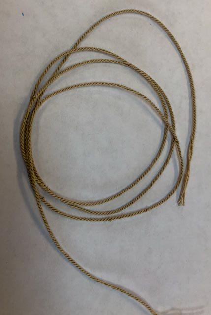
- 42 replies
-
- 6
-
-
- ropewalk
- rope rocket
- (and 1 more)
-
Hull modeling with Blender
SJSoane replied to SardonicMeow's topic in CAD and 3D Modelling/Drafting Plans with Software
I will be very interested to see how this compares to Fusion. Thanks for the step by step tutorials! Mark -
Hi druxey, I will happily leave high production to others. I will be very happy never to cast a cannon again after I get 74! Mark
-
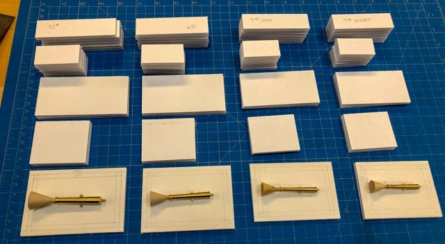
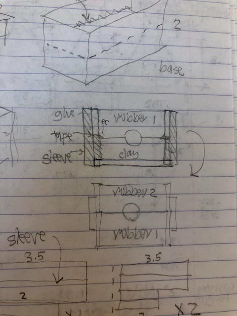
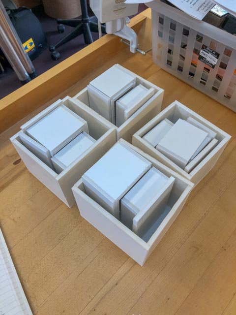
Hi everyone, Slowly moving along with the cannon, in between long bouts of shoveling snow. I built all of the boxes for making the moulds. I will be putting the cannon halfway into clay, as seen in David Antscherl's Fully Framed Ship, and in the excellent tutorial here http://modelshipworldforum.com/ship-model-casting-and-resin-techniques.php I learned from last time to make the box only the height of the clay at first, and then I will add another box on top for the first pour of rubber. I made the box the full height the first time, and then found it quite difficult to level the clay and work the clay against the master while reaching down into a tall box. This way, I can work the clay to the top of the box. I will have a sleeve to hold together the two levels of boxes when I am ready to pour the rubber, as seen in the sketch. While I was at it, I also made the boxes for casting the plaster of Paris around the rubber moulds. With four masters and five boxes per master, it turned out to be a lot of box construction. I did discover that the Byrnes tablesaw worked beautifully for cutting the foam core, as opposed to a ruler and scalpel. Everything was kept perfectly parallel and perpendicular. I epoxied the trunnions into the barrels, using the jig below to ensure that they projected equally on each side. And then best of all, Chuck's Syren cyphers arrived today. They are the perfect size for my cannon--thanks so much Chuck--and they look terrific on the barrel. It is a tiny detail that eventually eluded my own skills and tools, and I am sorry to have learned one of my limits. But looking at Chuck's exquisitely detailed laser cut cyphers on my barrel masters has convinced me that high quality done by someone else should take priority over not such high quality done by me (my wife very kindly described one of my efforts as looking like bird droppings on the barrel; painful to hear, but true). While I was at it, I ordered the mould clay from MicroMark. The clay I had previously purchased at an art store in Denver was stiff and difficult to press up against the master; hopefully this will be better suited to the task. Mark


-
Well done, looking good! Mark