SJSoane
-
Posts
1,655 -
Joined
-
Last visited
Content Type
Profiles
Forums
Gallery
Events
Everything posted by SJSoane
-
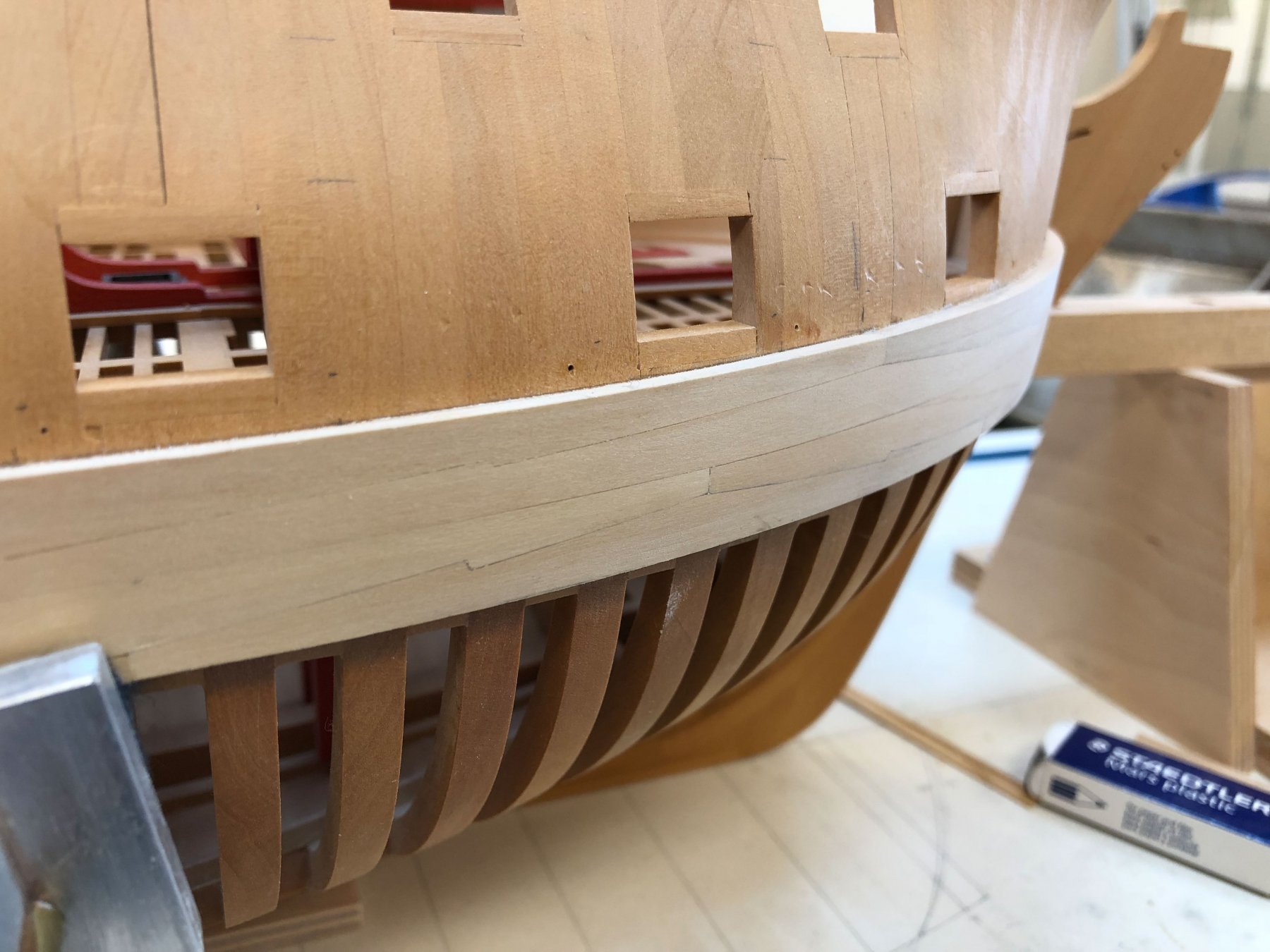
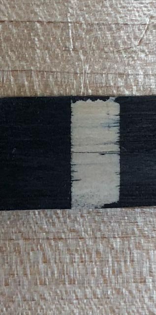
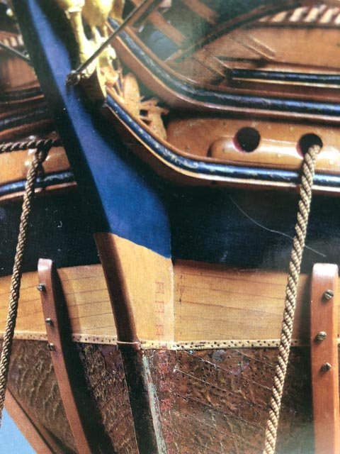
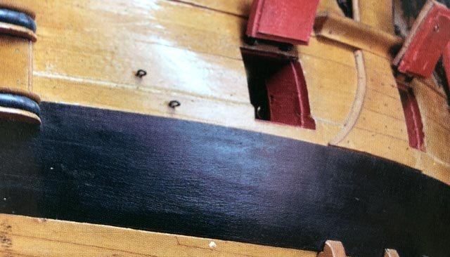
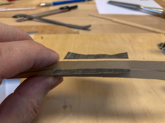
 Thanks, everyone, for the likes. And thanks, druxey, I may try upside down when I get to the multiple twist stern planks. For now, the straight side is going quickly--at least as quickly as I seem to be able to work. As I move along, I am scribing the lower edge relative to the top edge with a compass, to ensure parallel edges. I am trying to sand these lower surfaces to the correct size before attaching, because I need to protect the hull surface below which will always be exposed; no lower planking for me! I tried a sample of blackening using Fiebing's black shoe polish. However, I see I have a problem cutting a clean line as I will need to do on the stem pieces, as seen on the 2nd Bellona model below. On my sample, I used Tamiya model tape pressed down with a burnisher to make an edge; on the left side, I also scored the wood with a scalpel, I thought fairly deep. But both sides let stain run past the edge. Any thoughts on how to cut a clean edge using the shoe polish? I pulled out some samples I made a number of years ago, using Floquil flat black diluted to act more as a stain. It also ran under the masking tape. I will try Ed's Speedball ink next, but I suspect that since it is also watery, I will have the same problem. I don't want to point fingers, but look at the wiggly line painted on the Bellona model... Mark
-
Your loving restoration is really showing the beauty of the model! Mark
- 749 replies
-
- 6
-

-
- albertic
- ocean liner
- (and 2 more)
-
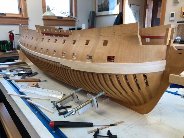
Hi Michael, thanks so much for the nice comments. And thanks, druxey, for guidance on the black strake. Work proceeds on the lower two strakes. These have proven to be more difficult than I expected, more difficult than the upper strakes. Perhaps because the hull begins to curve inwards at the lower level, combined with the challenges of clamping that low down and on the curve of the bow. I reached the flat section, and hope to pick up the pace before hitting the challenging stern section. Best wishes, Mark
-
Michael, Looking great! What are those short railings along the lower deck? Is it more obvious once the lifeboats are installed? Mark
- 749 replies
-
- 4
-
-
- albertic
- ocean liner
- (and 2 more)
-
Russ, what were those hatch covers made of in the real ship? Mark
- 420 replies
-
- 2
-
-
- captain roy
- lugger
- (and 2 more)
-
Gaetan, it is looking very nice! Mark
-
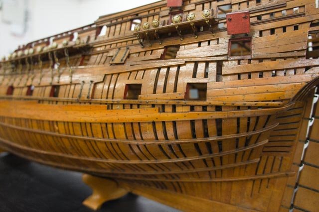
Thanks, everyone, this is beginning to converge on what seems to make the most sense. I will assume the Bellona scantlings were at the thinner end of these ranges, since everything seemed to grow larger towards the end of the eighteenth century. The scantlings for 80 gun ships in the 1719 and 1750 Establishments most closely match many other sizes for the Bellona 74 that I have been able to verify from other sources, so I will assume the 6 ½" for the thickness of the black strake as set forth in the Establishments and further stated by the Ship's Repository a few decades later. Looking at the fully planked Bellona model, this was of a constant thickness, although it does seem to have a rounded upper surface as seen at the gunport. And the later sources and the Bellona model appear to call for a 1'-0" width (plus ½" in some sources), close enough for me at 3/16" scale. In most of the primary sources that call for a second plank above this, they specify a plank 1" thinner than the wale, or 5 ½" in this case, wearing off to the 4" planks above. But this does not appear to be the case in the Bellona model itself. The difference in thickness between the black strake shown in the model, and the planking directly above it, looks to be more like 2" --since the planking above is 4", this exact difference would be 2 ½". And so there appears to be no special second plank above the single black strake with its rounded top, just the normal 4" planking. Given this, I am inclined to follow druxey's lead here, and use a single strake, not painted, 6 ½" X 1'-0", with a rounded top. So why would the Bellona model use only one black strake, as called for in the Establishments that finished in 1750, and not two strakes, as called for in all of the sources and all of the contracts for individual ships a few decades later? I will assume that the experimental Bellona design in 1758, the first 74 in the British navy, drew upon the last Establishment revision of 1750 for most or all of its scantlings. As best I can tell, the old 80 gun ship in the Establishment was about the same overall size of the new 74; so why not use the well-tested scantlings for a ship of that size? The creative energy would have gone into changes in deck and gun layouts to convert from an 80 to a 74 of the same size, not changing the fundamental fabric of the structure. And of course the later 74s following in the footsteps of the Bellona grew increasingly larger; and so a few decades later, their scantlings would have likewise grown. Interesting that an additional transitional strake above the black strake creeps in over the next few decades. I have no idea for explaining this evolution! Druxey, did you round the top of your black strake, like in the Bellona model? Mark
-
As I wait for planks to dry after steaming, I started looking at the black strake again. Since the Bellona was a transitional ship designed in 1758, between the earlier Establishments (finishing in 1750) and the later consolidations reflected in Steel (1805) and the Repository (1788), the scantlings are not easily confirmed. Here are the data points on either side of the Bellona's time: Only establishment shown in Allan Yedlinsky's book is for 1719 for an 80 gun ship--because the Bellona was the first 74-- (blank for 1745 and 1750 because presumably the same): "One strake above [the wales] 6 ½" thick." (and no width specified). Steel: 2 strakes, one 7" X 1'-1 ½", the other 6" X 1'-0". Repository: 2 strakes, one 6 ½" X 1'-0", the other 5 ¼" X 1'-0". Brian Lavery's book on the Bellona calls for 2 strakes, 6 ¾" reduced to 5 ½", but this has no reference to a primary source. My own photo of the Bellona first model does not seem to show a black strake (at the stern, the wale is showing 5 strakes rather than the specified 4, so the partial upper one must be the black strake but it is the same thickness of the rest of the wale; not helpful). Very compelling is the photo of the second Bellona model, shown on Lavery's Ships of the Line cover (see photo below). It appears to show only one strake thinner than the wale but thicker than the planking above, and compared to the width of the wale (4'-3"), this black strake appears to be about 1'-0", the width of individual strakes called out in Steel and the Repository. And then there is the very good discussion on Gary Shipwright's build log with Gary and druxey (page 14 in the link below), which suggests that there is an additional strake above this one, that tapers from the black strake to the planking above. Assuming the lower strake is 6 ½" thick and not tapered, and the planking above is 4" plank, then the second black strake would be 5 ½" tapering to 4". At 3/16" scale this will be very subtle! Mark
-
Mark Who would ever guess that those cannon would take so many parts? It looks so simple when it is all done; only the builder knows for sure! Looks good. Mark
-
I further recommend the Tamiya tape. Used that a lot building plastic models with my son years ago, and it has transferred nicely to wood projects. Mark
- 420 replies
-
- 3
-
-
- captain roy
- lugger
- (and 2 more)
-
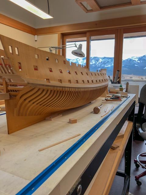
And thanks, Hubac'sHistorian. The mountain view makes up for the remoteness. And the long winters provide more inside time in the shop!
-
Thanks, druxey.
-
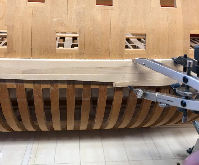
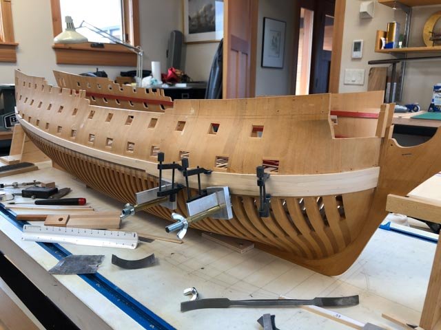
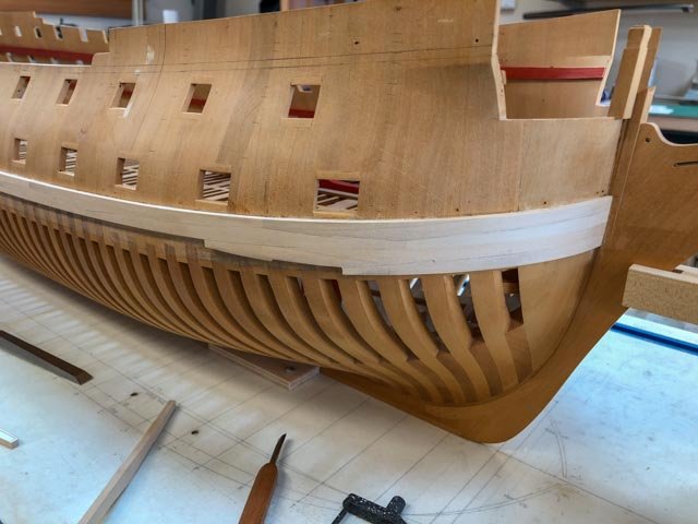
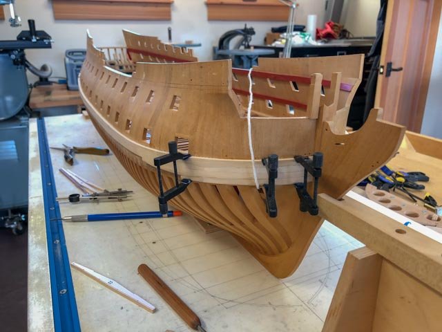
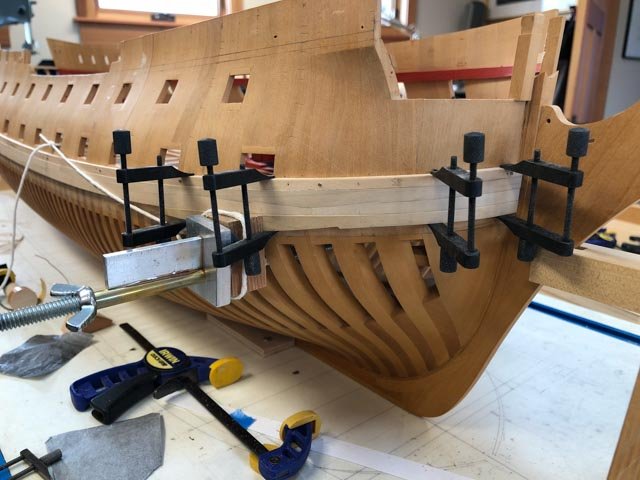
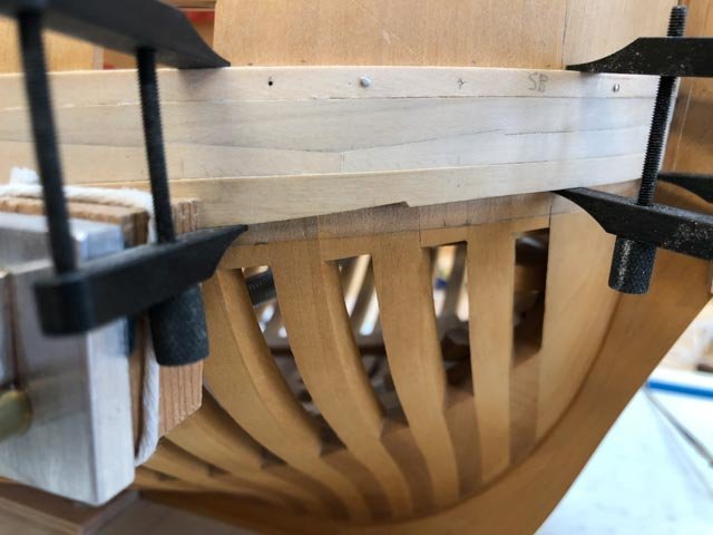
Hi everyone, Thank you, everyone, for the helpful suggestions. It turns out that it was spiled accurately but it had the opposite of spring-back from the steaming and bending; it was bent a trifle too much, so the middle was sitting about a 1/16" away from the hull in the longitudinal direction while the ends were touching the hull. Finger pressure was enough to get it in place. So after trying a number of failed clamping ideas, I went with Greg's suggestion to use spots of cyano in between the carpenter's glue. After experimenting with a few spare pieces, I just went for it. It took rather longer than 90 seconds to grab, and I was able to get some vertical clamps in. And all held well. Nice to have that behind me, and I learned a new good trick. I also took off the batten, because my clamps are too short to span the entire wale plus the batten. Without the batten, you can begin to see the true lines, as in the second photo. Mark
-
After more careful fitting of the lowest, foremost plank, it bows in the center, keeping the two ends tight against the hull if I can just pull the center tight to the hull by about 1/16". I am contemplating a Spanish windlass, using a cord I managed to thread under the gundeck to a point on the port side opposite the line of force needed. If I smoked, I would smoke a pipe now while contemplating whether this would distort my hull or put creases in the hull where the cord is pulling tight. Since I don't smoke, I will try gently tightening to see whether things start creaking or not. Mark
-
Hi Russ, I just had a chance to catch up on your project. It is looking very nice! Mark
- 420 replies
-
- 3
-
-
- captain roy
- lugger
- (and 2 more)
-
Now I am too scared to proceed, with thoughts of blood, glued fingers, watching clocks....🙂
-
Thanks, everyone, these are very helpful suggestions. In hindsight, I now know it would have been better to build the wales before building the gun deck. I was just very curious about what the gun deck would look like all those many years ago! Greg, did you alternate cyanoacrylate with carpenter's glue, within each inch of your gluing process? Is there any problem if they interact or mix together? Best wishes, Mark
-
Hi Paul, Do you have a source for those, or a brand name? They look handy. A challenge I have with the lowest, foremost plank is that the gun deck is higher inside than the wale; so the inner side of the clamp cannot be aligned opposite the outer side of the clamp on the wale. It has to be made asymmetrical. But maybe there is a way to extend one of the arms. Best wishes, Mark
-
Greg, I think I now know the answer to your earlier question. The piece I just fitted is the longest plank in the wale, and it wraps so far around the bow that pulling it up tight towards its aft end tended to pull everything into place. The next lower piece, which I am showing in the first photo before beginning to fair it, is much shorter. And the vertical clamps pull it away from the hull, just as you asked about. I will need to clamp it in the fore and aft direction. And because my frames run only athwartships, I have no easy way to clamp fore and aft, or perpendicular to the wale on the diagonal to the hull. My first thought is to construct a device, shown in the second drawing, that would slip a piece of plywood between the frames, and then use this to bolt a former that would tighten up against the wale. But it will need cut-outs, so I can still get the vertical clamps in place. Looks like a long uphill project at this point in the day. Might look better tomorrow. Mark

-
Hi Greg, Interesting you ask that. The upper planks definitely needed some clamping pressure onto the hull, not just up to the batten. But this one fit really well, and the clamping to the upper strakes seemed enough to hold it against the hull. I had to put the horizontal clamp at that particular place because it was bowing out just a bit. When I first offered the plank up to the hull, it looked like the spiling had given it too much fore and aft bend, and I had to push the two ends up when I started fine tuning the joint. But after a while it just began to fit into place without much clamping pressure anywhere. I had left this plank in the former after steaming for a couple of days, because I had gone out of town and just left it for when I got back. It had less spring-back than usual, which is perhaps why it fit a little better. I dread the thought that I have to leave pieces in the former for a few days. I will leave the equivalent port plank in the former for just a day, and see if this was an issue or not. It just goes to show that no matter how much I try to perfect a process, it always throws a new twist, both good and bad! Mark
-
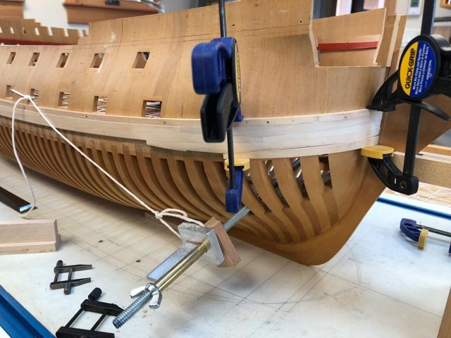
Thank you, Greg, druxey and montañes. Not boring comments to me, greatly appreciated! I forgot to point out the challenge of clamping at the round of the bow. I had to cut angled blocks as seen in the previous photos, to match the angle of the wale at the clamping point. But the angle means it tries to slide off when tightened. I tried tying it back with string, as seen in the photo (gave me practice tying a bowline knot), but this was insufficient. In the end, a strong C-clamp right next to it was enough to keep it in place. Mark
-
Hi Siggi, Your planking is beginning to show the lovely lines of the Tiger. And very nice mouldings! Mark
-
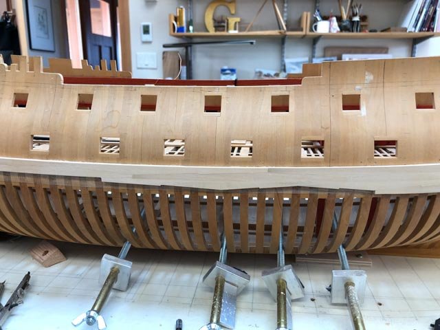
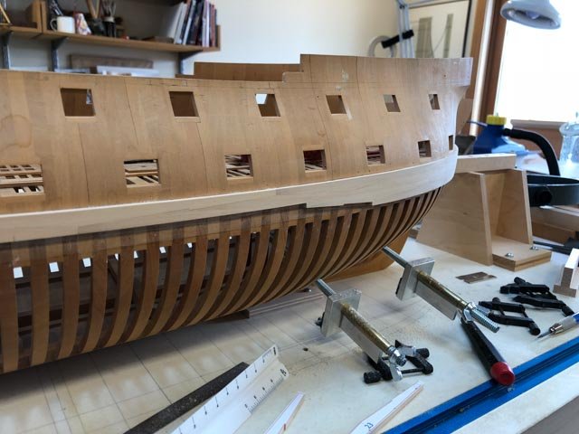
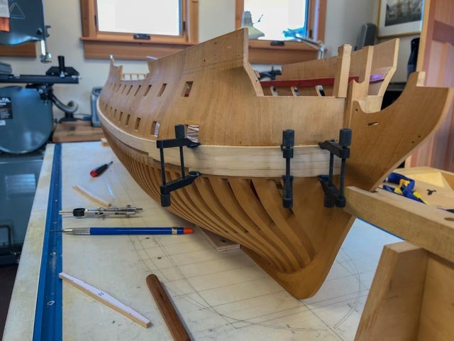
Away for a few days, to the annual Charlie Russell art auction in Great Falls, Montana. Some of the best Western traditional art in the US. I can't afford to buy any, just look and admire... I am continuing with the wales. I fitted the foremost, lower two strakes before bending, using artist's transfer paper squeezed between the two pieces. This notes high points which are then lightly filed down, and the two are tested again. With patience, one can sneak up on a very tight joint. The second photo shows dry clamping for fit after the bending, and a closeup in the third photo. Interestingly, the plank was carefully spiled, but it still needed a fair amount of adjustment using the artist's transfer paper. I think it has to do with the constantly changing angle of the upper surface, since most of the high points were on the inner edge. Glue tomorrow! Mark
-
Thanks, Ed, I knew there would have been some extensive testing involved in this decision. This makes perfect sense.
- 3,618 replies
-
- 2
-
-
- young america
- clipper
- (and 1 more)
-
Dear Siggi, I have wondered about planking before the upper decks are installed. Would it help to install some temporary ties along the deck levels, like the ones you already installed at the stern? Mark