HOLIDAY DONATION DRIVE - SUPPORT MSW - DO YOUR PART TO KEEP THIS GREAT FORUM GOING! (83 donations so far out of 49,000 members - C'mon guys!)
×


SJSoane
-
Posts
1,649 -
Joined
-
Last visited
Content Type
Profiles
Forums
Gallery
Events
Everything posted by SJSoane
-
 Thank you, albert, Marc, Mike, Greg and druxey, for your words of support and encouragement. This cannon project seems to have been an exceptionally long time in development this winter, and I haven't even begun mass production. Your continuing support really helped keep me going when the project got a little bogged down at times. Thanks again to Chuck for providing those exceptional king's cyphers. They look great in the casting, and I concede that it was beyond my ability to create them after numerous failed efforts. I may still try photo-etching when the sun comes back this summer, just to see if it was a problem with using an incandescent bulb instead of the sun... Greg, I haven't seen the idea of a cutter; intriguing. Do you recall where you saw it? I am reworking the split collar for clamping the barrel in the lathe, because it is still not quite centering the drill. I will show experiments as I work on it. druxey, I last used Jax's Pewter blacking on earlier experiments, which seemed to work well. But I have noticed that some cannon treated this way a few years ago lost the blacking in a few places like edges on the face of the muzzle. Do you have thoughts about how to clean the barrels for Jax's to work better? And my Jax's is a few years old; do I need to get a fresh supply? Thanks again, everyone, Mark
 -
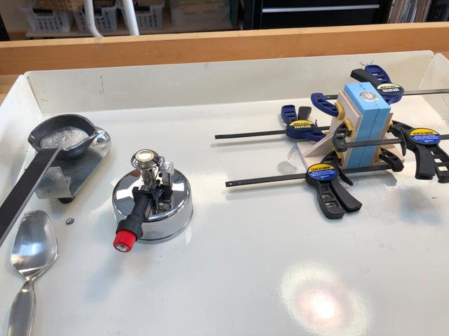
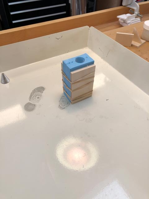
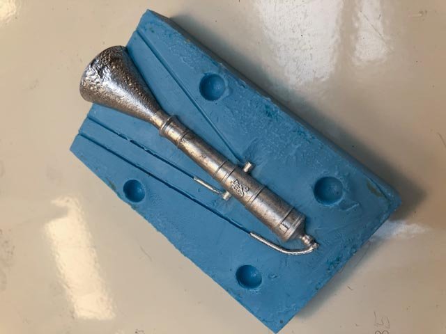
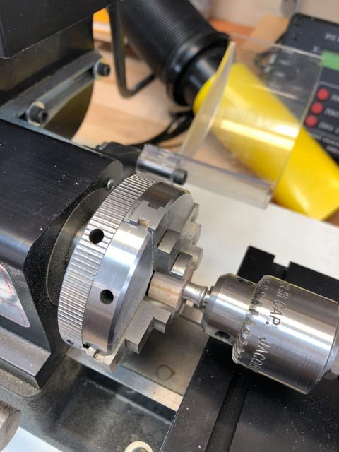
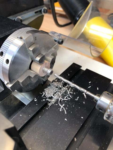
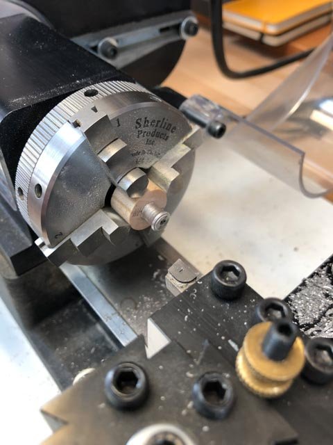
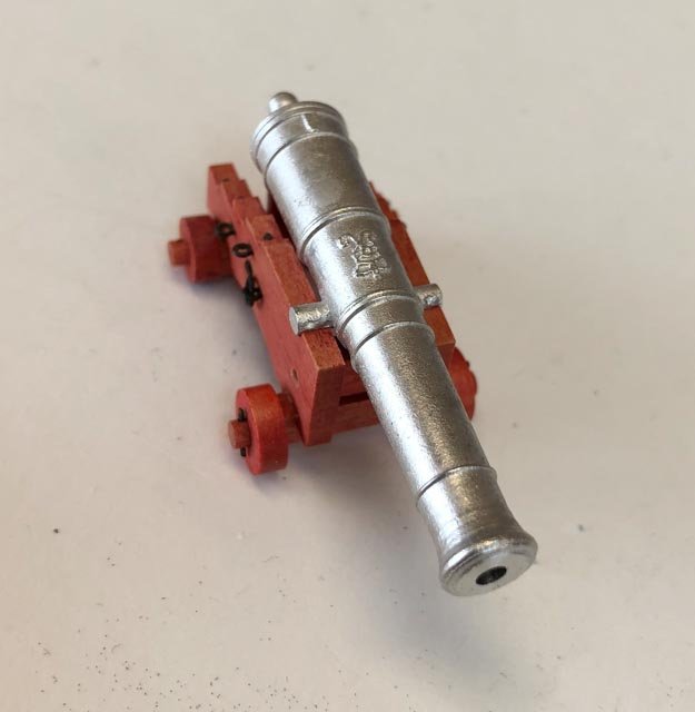
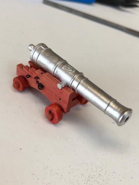
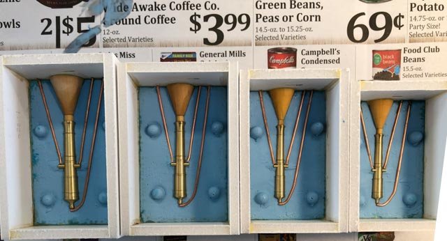
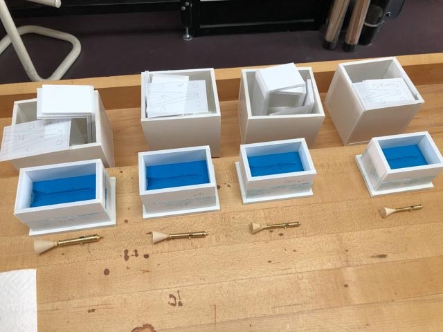
I picked up a cold on the plane back from our trip, which slowed me down the last week. But now better! I initially tried building a Plaster of Paris sleeve around my moulds, to stabilize them and pull the two halves together securely. But I had trouble pulling them tight with tape before pouring the plaster; for some reason, this time, the tape just would not secure tightly to the rubber. And then I used old plaster, which was so lumpy and needed breaking up that it began to harden before I could pour it into the boxes. I had to throw all of that away. Reading the Micro Mark instructions again (when in doubt, I keep telling myself, read the instructions), it suggested pressing the moulds halves between two pieces of wood. I initially tried that using clamps, but this distorted the mould and I cast an oval section gun. So then I tried holding them together with rubber bands (per the instructions), and this worked well. Here is the first cast: Once I cut off the gun head with a jeweler's saw, I clamped it in the lathe, using a chuck on the protruding end of the muzzle to center it, and then clamping it in a four jaw chuck using a split ring of wood. Then I could drill for the bore, and face the end. And the result: Needs a little filing to clean up the trunnions, but the process seems to work. Mark
-
Gaetan, Beautiful knives! Let us know how they work! Your photos look like they are taken inside a real ship. Beautiful construction. What camera lens are you using to keep such great depth of field? Mark
-
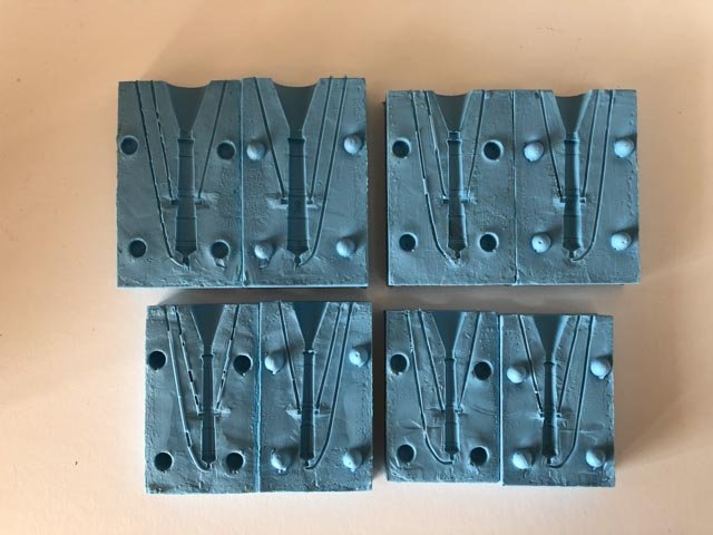
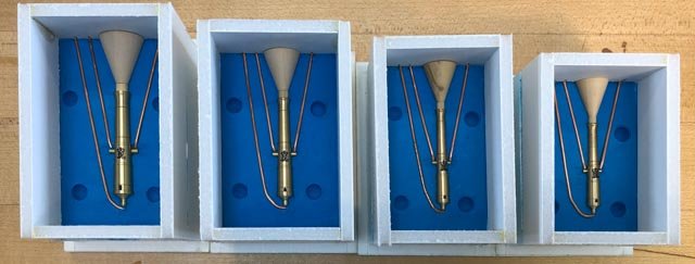
Thanks, druxey, it is amazing how many details seem obvious until you start actually working with them. The rubber pours were successful! No bubbles, good rendition of detail including the king's cypher. I did have a moment of concern when the two halves intially would not pull apart, but once I peeled off the outer paper boxes, the rubber came away nicely. Plaster of Paris sleeves next. Mark
-
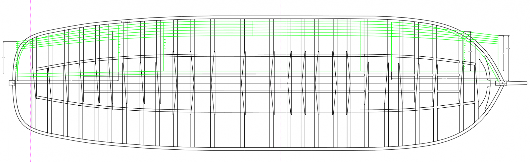
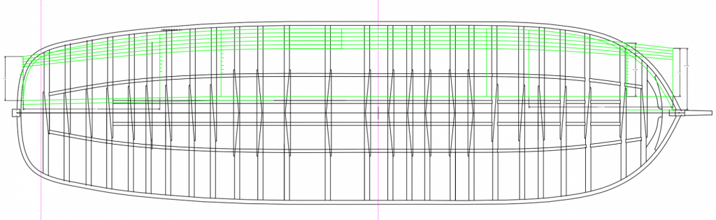
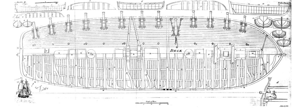
Hi druxey, Retirement seemed like a good idea until I discovered that my brain flew out the window. When I was juggling a dozen things, I could still keep track of details. Now I have only one thing to juggle, the details slide away. Or, maybe it is aging! So here are some decking questions, while my moulds dry. I am laying out the decking for mounting the guns, likely building 5 strakes from the waterway to accommodate the length of the guns. Do I have it right that a 3 or 4 shift planking plan has all of the butts falling on beams, not any ledges? This means that the lengths of the strakes are quite irregular, given the irregular spacing of the gundeck beams (see above). Is there any particular functional or historic reason to choose 3 or 4 shift planking? Goodwin suggests that weather decks were 4 shift, but I see no other information pertaining to the gundeck. I am assuming that the planks taper at the bow and stern, as Falconer shows. I am also assuming that there is NOT a band of anchor or top and butt planking adjacent to the waterway in this ca. 1760 ship. Goodwin (p. 59) says that this practice came in only at the end of the 18th century. Mark
-
I poured the second rubber for the first two boxes, all went well. Then I started pouring for the final two boxes, and just as the stream started into the box I realized that I had not coated them with mould release! Retirement seems to have addled my brain. So I mopped it out, and will have to wait until it dries to make sure there is no rubber left from the aborted pour before starting again. While waiting, I started working on the planking plan for the planks under the guns. I have copied the run of planks from Falconer. Next, working out the plank ends. Michael, I should have paid more attention when you pointed out the coffee add under the moulds. It is even titled, "Wide Awake Coffee"... Mark

-
Marc, I just managed to read through the entire log. Very impressive research and thinking. Now I understand your name "Hubac's Historian"; well earned! Mark
- 2,697 replies
-
- 3
-

-
- heller
- soleil royal
- (and 9 more)
-
Hi Marc Many apologies, this is the first I came across your build site. I will be looking in regularly now! Mark
- 2,697 replies
-
- 3
-
-
- heller
- soleil royal
- (and 9 more)
-
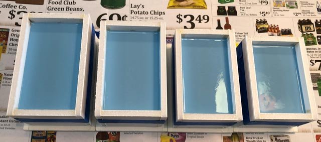
Thanks, Marc, Mark and Michael, for the good thoughts. My challenges with technology in photo etching have spooked me a little when I get outside the realm of wood. So here is the first pour of rubber. Won't know if I got a good pour without bubbles for another 4 hours or more. Also, let me know if that is a good buy for potato chips in the background...😀 Mark
-
Michael, That was fascinating reading on the history of navigation lights. Thanks! Mark
-
Hi everyone, The sprues are now installed in the moulds, as well as the locating dimples. I took extra care this time to clean up the clay at the edge of the master. Last time, I left the clay either a tiny bit high or low, and this creates a thin edge on one side of the mould or the other, which deteriorated over time. So I spent a lot of time with a sharpened toothpick to get these as clean as I can. Probably pouring rubber tomorrow. I did read on the instructions on the rubber mould material that I should use the rubber to rubber release even on the box sides and the clay. When in doubt, read the instructions...😀 Mark
-
Outstanding craftsmanship, Johann! Mark
-
So here is a dumb question; when did the convention of red and green lights come into international usage? Mark
-
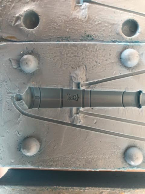
Putting aside the breeching rope for some thinking time, I have moved on to casting the cannon. I am setting the masters in the clay moulds, ready for the rubber mould pour. Can someone remind me what to use for a release agent between the clay and the rubber mould material? I can't find this anywhere in my notes or sources. Do I just use the release material for rubber to rubber? Mark
-
This seems to be just like the world of CAD in architecture; you start out with what looks like it should be fairly automatic and rational, and end up with hours of tweaking to make it really right. My reality never quite matched the smooth and simple tutorials. It is fascinating to see you all working out the kinks in these programs for shaping ship hulls. Mark
-
cable laid vs rope (left vs right twist)
SJSoane replied to davec's topic in Masting, rigging and sails
Reading Steele's Masting and Rigging tables, he identifies certain specific lines as "cable laid". This includes large stays, but also sheets and tacks. So it is not necessarily specific to standing or running rigging. Would "cable laid" in Steele's tables be the S direction as Bob explains so well above? Mark -
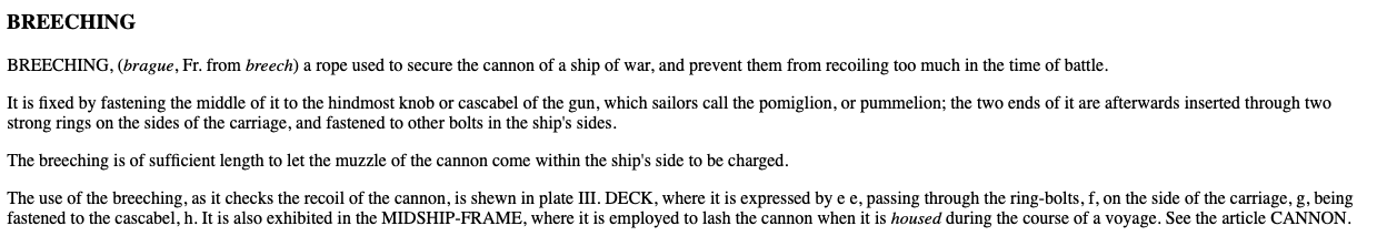
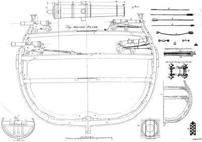
Hi everyone, Yes, the upper drawing in Falconer (18) clearly shows the rig without a breech rope. Why the tackle is shown tied to the button I have no idea. As we all look at (19) more carefully, it is admittedly a little confusing. That rope shown in the breech position is clearly too thin. And yet, it reeves through the ring and eyebolt on the side of the carriage, which is where the breech rope goes. And Falconer's text referring to this drawing says that it shows the breeching rope "where it is employed to lash the cannon when it is housed during the course of a voyage." I have no idea why he shows such a thin line for what he is calling the breech rope. I can't imagine replacing the thick breech rope for a thinner line when the cannon is stored. When we look at the gundeck plan, his text referring to this says "the use of the breeching, as it checks the recoil of the cannon, is shewn in plate III. DECK." So this shows the gun run inboard for loading, not for storage. druxey, I think you are right that the breech rope must have been tightened up at one end when the cannon was stored. Falconer's deck drawing shows the rope as too long in its action length to tighten up for its storage length. I also find it interesting that the position when pulled fully inboard does not leave a lot of room for swabbing out the cannon and inserting a new ball. The ramming rod must have been projected out the gunport when in use. I wonder how many fell overboard in the heat of the moment? So one lesson from this closer inspection is that the drawings themselves might have some inconsistencies in them (like the thickness of the breech rope); and so might we fear that the arrangement of the breech rope at the button is also simplified? And likewise with the photo of section of the Royal George; might we fear that the breech ropes were replaced much later in a renovation of the model, by someone who did not know any better? How far can we trust our primary sources? Need that time machine again. Druxey, I hope your steampunk design is well underway! Mark

-
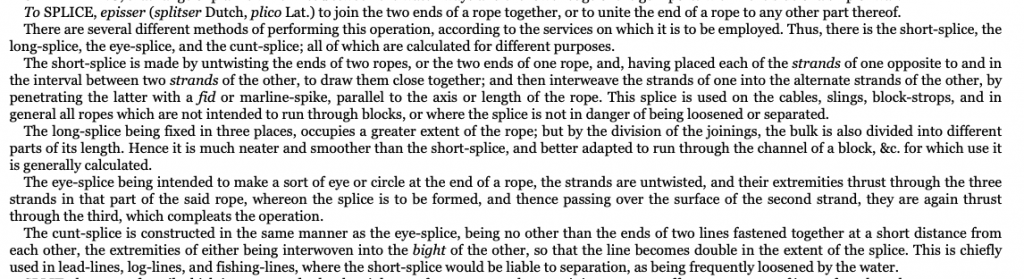
Thanks, everyone, for continuing ideas about what I had assumed until now was a very straightforward detail. Gaetan, I like your idea of giving the ship to French, and renaming it Le Bellona, because Boudriot's drawings are a delight to view. But I think the British on this website would object to me giving over a British ship to the French without a battle....😊 Beautiful photos of your old project, by the way. druxey, I have been thinking again that a cut splice would also be consistent with the drawings we see in my favorite source, Falconer. Falconer does list this splice (he spells it the pre-Bowlderized form below). He does not explicitly refer to the breech rope for this splice; although this is not in itself a reason to reject the idea. And Kevin, your very interesting drawing could be a cut splice as well, but with some seizing at the joins. Paul, thanks for going out into the cold to get a picture! It looks to me like this cannon is of the later date, when a cast iron ring was formed into the cannon itself. As we have all struggled here with how this worked earlier, it is very easy to see now what an important invention this was, to cast the ring right into the cannon. Elegant solution to a difficult detail. Chuck, your detail is consistent with earlier comments druxey made, referencing a "turn around" the cascable. This one makes the most sense, along with the cut splice, as a clean and functional answer to this detail. I just wish the Falconer drawings showed something closer to this, and I would be happier with taking it up. It is an outside possibility that Falconer simplified his drawings at such a small scale, I will admit. At this point, the ideas most appealing to me are the simple drape over the button with a seizing, as Siggi recently showed (most consistent with the two contemporary sources, the Royal George section and the Falconer drawings), or a cut splice, which is more functional, and could be inferred in the Falconer drawing but not the Royal George section. I may decide this once I start trying to rig the cannon, and see what suggests itself as more appropriate. Best wishes, Mark
-
Siggi, thanks, sometimes the simplest is the logical answer. This would be consistent with everything we see in the Royal George model and in the Falconer drawings. And this I can make! Mark
-
Wow, a masterpiece! Mark
-
Aha, Alan, that looks about right. I doubt I will get this done at 3/16" scale, but it is good to know how. The thinnest thread I have is the equivalent of 1 ½" circumference rope. Mark
-
Hi druxey, Good point about the problem if the breech slipped up over the barrel. After reading Falconer, I will assume it was seized onto the button; and this would have been a good reason why! Do you have an idea how a grommet would have been formed on the middle of the breech rope? Would the ring of the grommet have legs on either side that are wrapped into the seizing around the breech rope? Mark
-
Gaetan, Amazing work. Your tools down in the hold show just how large this project really is! Mark
-
Michael, I add my congratulations. Astonishing work. We can learn so much from you. So how, exactly, did you make the circular former for the top? I see a file working on the side but not how you turned a perfect convex circle. Done on the lathe? And what pressed the metal into the former, once you had it in the vise? Mark