SJSoane
-
Posts
1,655 -
Joined
-
Last visited
Content Type
Profiles
Forums
Gallery
Events
Everything posted by SJSoane
-
 druxey, I was thinking the same thing!
 -
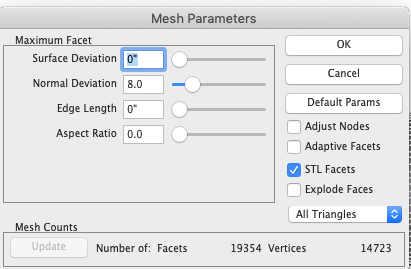
I just converted the file to STL, which is what Shapeways asked for. But it is quite faceted. Is this the best I can expect for a 3-D file? I saved it as a Binary file, although there was a choice for an ASCII file. There was also a choice for number of facets in the Binary option, I have shown the default that I chose. Apologies for the dumb questions; this is my first ever effort at 3-D printing, not quite sure where I am heading. Best wishes, Mark
-
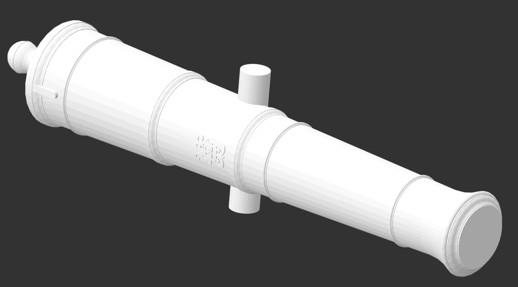
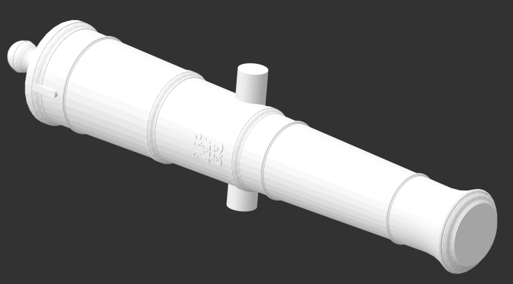
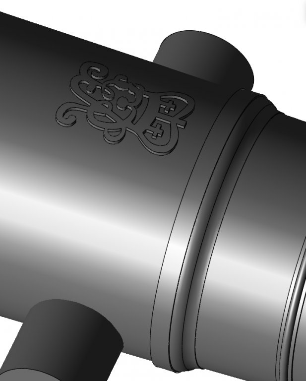
Thanks to great help from our colleagues on the CAD section including Alan, I managed to create the king's insignia in the digital file. I will try getting a 3-D print of this, just to see the quality. Although I have heard that 3-D printing is not quite up to snuff at this scale. And while waiting for that, I will continue with the duplicator... Mark
-
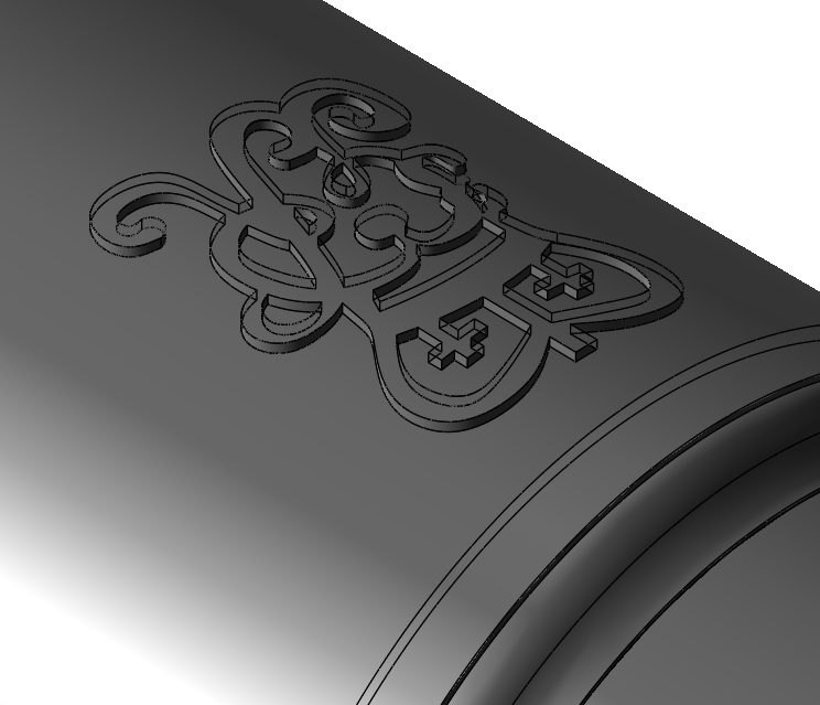
Aha! Got it. Not quite sure how. I had to create a cover skin of the line drawing, then pull the skin into a solid, then subtract from it a female mould of the barrel shape + ¼" radius. Then add to the barrel. druxey, if I can figure out how to profile this with rounded edges, I will come out of retirement and start a CAD business!☺️ But thanks for the photo; it is great to see what we are trying to approximate here. Mark

-
More work, it seems I have projected the walls, but not the top surface. At least I figured out how to make a female mould of the curve above the insignia, which I used to subtract from the top of the insignia. Now I just need to find out why I am not creating a top surface...
-
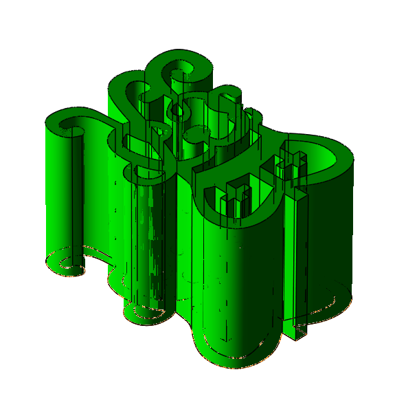
Thanks, everyone, for these helpful suggestions. I am making a newbie mistake somewhere. However I try to extrude or project the insignia, I get an ill-formed solid, as seen below. Turbo Cad Mac is not very good at identifying the problem areas. When I first attempted to create a solid out of the line drawing, it said there are duplicated or overlapping curves and will not proceed. Unfortunately, sometimes it showed me where the offending problem is, sometimes not. I thought I had fixed them all when a tool like extrusion allowed me to proceed instead of calling an error. But when I proceed, I get these ill-formed solids. This image below is based on a drawing of control point splines. I have tried converting this drawing to interpolate splines, simple curves, etc. but the solid is still ill-formed. I will keep trying edits to see if I can at least get a clean solid from which to try the good suggestions above. I just wanted you all to know where I was with this.... Mark
-
Pat, thanks, I was wondering about that. I will have to see if I want to invest in an upgrade. I am not sure how far down the road I am going with this 3-D printing quest as it gets more complicated and expensive! I will contact TurboCad and find out more. Thanks again, Mark
-
Thanks, Alan, I will look for something like that in TurboCad... Mark
-
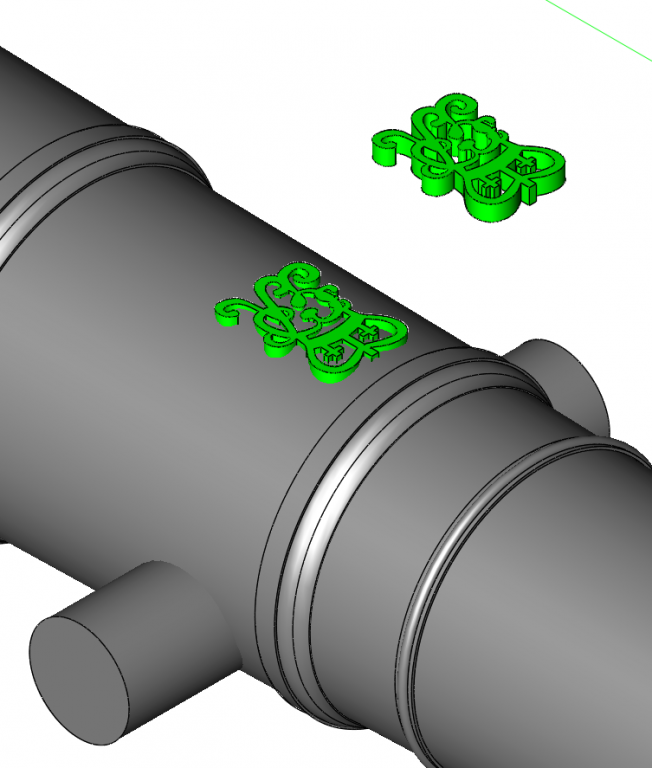
I am working on a digital file for 3-D printing cannon for my Bellona project (in the scratch-built section). I am using TurboCad for Mac Deluxe version 10. I have made the insignia a solid, as you can see below, but I can't figure out how to curve its upper surface to match the curve of the cannon. Also, how to merge the insignia into the cannon so there are no gaps or intersecting solids between the two. I assume this would be a bad thing when creating the file for the 3-D printer. Can anyone help with this? Best wishes, Mark

-
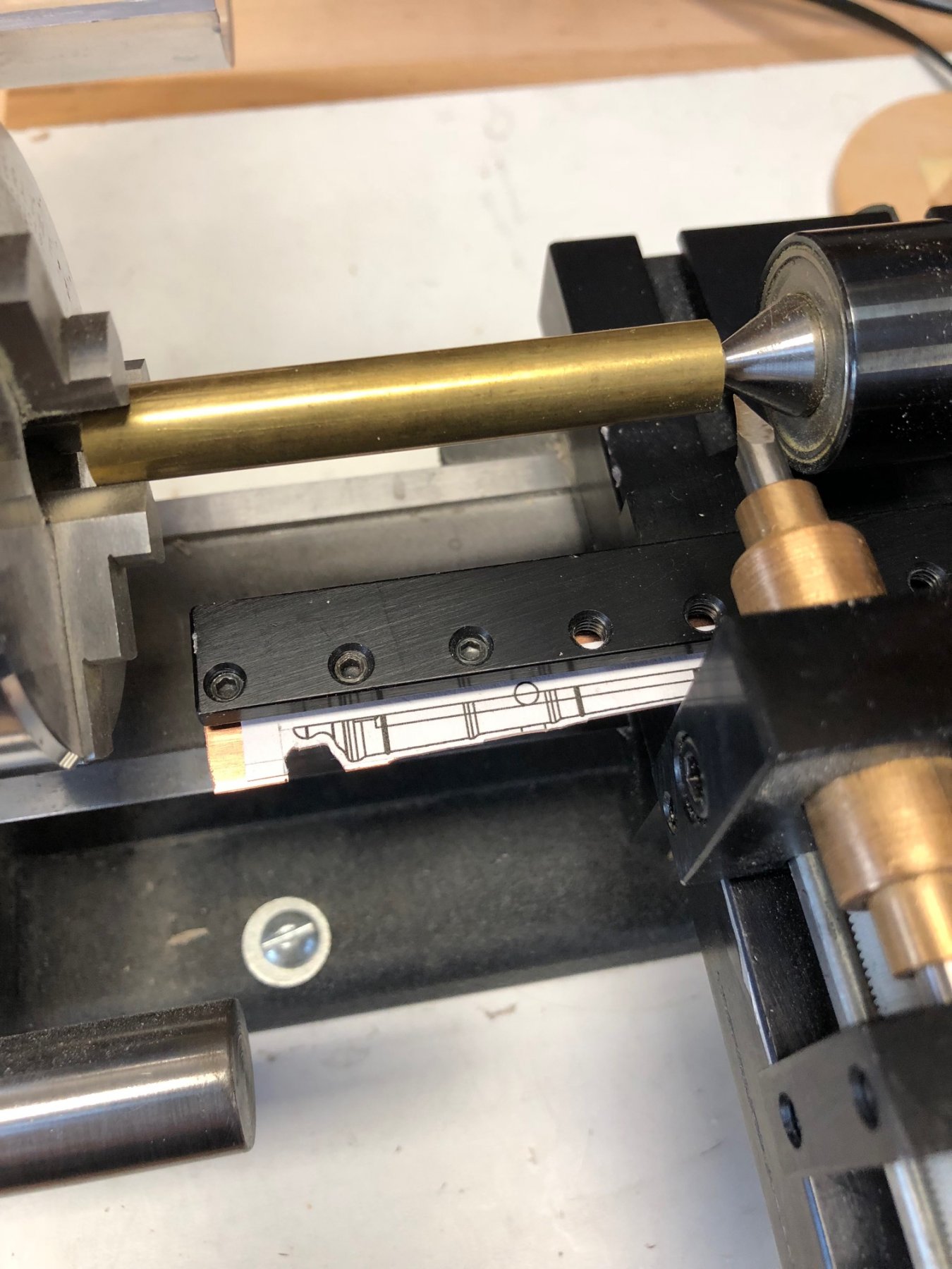
I am proceeding with fabrication of the cannon. I decided that this would be a good time to try a couple of strategies, to see which one gives the best results, and also to build my skills in a few new things. I will try duplicating from a template, reworking the casting I tried earlier, and 3-D printing. I have started making the the duplicating template, as seen below, and also creating the digital file for 3-D printing. Regarding the digital model, I am struggling with how to get the king's insignia to curve to the gun surface. I am using TurboCad for Mac, if anyone has a suggestion for doing this. I will also post this question in the CAD part of this website. Mark

-
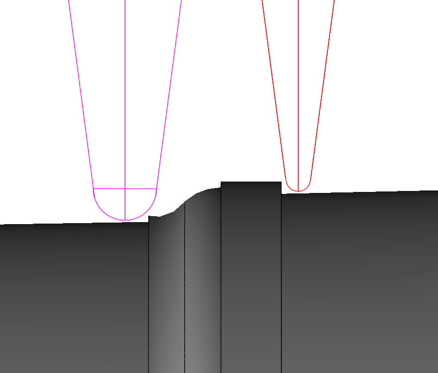
Hi Alan, You are quite right. I went down this rabbit hole purely out of historic interest. The actual fabrication cannot likely reproduce the finer points. I have drawn my lathe duplicator cutter and follower to the size of the actual barrel, as below, and I can see that some of the moulding profiles will not be captured. But I guess like everything else in this model, at least I will know what SHOULD have been there! Mark
-
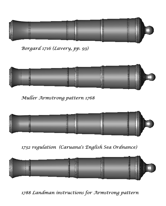
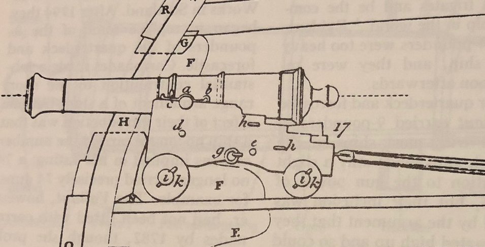
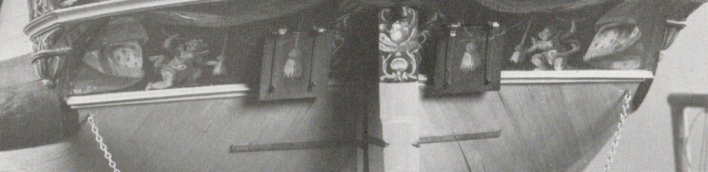
Hi everyone, Thanks to all of you, I now have a more sophisticated (that is, confused in a thoughtful way) understanding of the guns. Below are the guns I have tried drawing, starting with the Borgland gun in 1716, then the Armstrong pattern described by Muller in 1768, then the 1732 regulation based on Armstrong, and then Landman's 1788 instructions for an Armstrong. Let's compare these to the drawing in Falconer's Dictionary of the Marine, which I have taken as the closest image I have to the Bellona's time. The Bellona was launched in 1760, and the Falconer book was first published in 1769--although I have only seen editions from the 1780s, and so I cannot be absolutely sure that these drawings were original to the 1769 edition. Has anyone seen the 1769 version of Falconer, and are the drawings the same as in later editions? Assuming the Falconer drawings date from the 1760s, how do the various patterns compare to this? The Borgard has a cascable with two ovolo mouldings (half circles), but the Falconer has an ogee (S shaped). So the Bogard is out. The Landman has too fat a neck and button on the cascable; and the chase is too slender. So the Landman is out. The Muller version of Armstrong and the 1732 regulation based on Armstrong seem very similar. But the 1732 drawing shows a more complex cascable than the Falconer; the Muller version of Armstrong looks more like the Falconer drawing. And the Muller version has a longer, more slender neck than the 1732 pattern, more like the Falconer. I am therefore settled that the Muller version of Armstrong is closest to what I think the guns would have looked like in 1760. Siggi's excellent photos do challenge these drawings a bit. If I read Siggi's photo relative to the text correctly, the two cannon closest to us in the second photo are labeled as Armstrong patterns; but their muzzles have a more gradual slope than either Muller or the 1732 pattern is showing. Could these all be from a later date, like Landman's instructions from the 1788? The beautiful cannon on the red carriage looks a lot to me like the Landman instructions, with the more slender chase. I think this is the most handsome cannon of them all, but I will faithfully follow what I now think is most historically accurate for the Bellona, the Muller version of Armstrong. There is one last puzzling question, as I finish up drafting these cannon. The Muller instructions give the same width for all of the reinforce rings, ogees and astragal mouldings, no matter what the caliber gun. This doesn't seem consistent with the 18th century reliance on proportion relative to size, and they seem outsized on the smaller guns when I begin to draw them. I think I will proportion these down as a function of their relative calibers. Mark

-
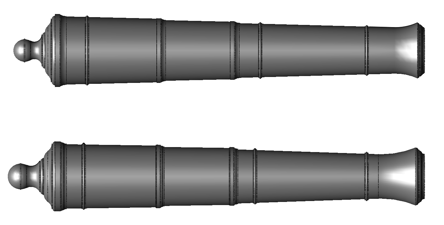
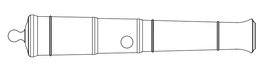
hi everyone, After a break for the American Thanksgiving, I got back to the guns. Siggi, that link you provided above is very remarkable. It gives very precise instructions on how to draw an Armstrong pattern gun, quoting Isaac Landman's instructions from 1788. For those who haven't seen it, it has an interactive section where you can choose a gun size, and it will draw the gun for you. Well worth having a look at it. It gave much better information on details like the muzzle and cascable, so I tried his instructions. Interestingly, it creates a slightly different profile than the one I previously drew based on the one in Adrian Caruana's English Sea Ordnance showing the 1732 Regulation. Below, the one at the top is based on the Caruana drawing, the second is constructed from the Landman's instructions. Both purport to show an Armstrong pattern. But notice a couple of differences. The cascable is longer in the Landman, with a broader ogee (the S shaped curve) and the button has a larger diameter. Also, the chase tapers at a somewhat sharper angle than the two reinforce sections, giving the Landman gun a more graceful profile in my opinion. And the muzzle flare is a touch longer. It is beyond my research skill at this point to know which is the real Armstrong pattern, or whether it evolved over time while keeping the same name, or were these various authors looking back to different periods of development? The Landman profile does look like an effort to slim down the gun, which I understand was a desired effort through this period. I have appended the Falconer gun from the date of the Bellona, for comparison. Each step forward raises more questions! But that is the fun of this project. Mark


-
Bill, Thank you so much. This was a treasure to find. As it turns out it reproduced the diagram from the Muller treatise that was obscured in the Goggle digitalization. What a great magazine, looking quickly at some of the other issues and articles. Another day's research and drawing, and I discovered several interesting anomalies. First, as best I can tell, it appears that M.V. Brewington sometimes used shot diameter, and other times caliber, in calculating dimensions. So Hahn was following him. But the Muller description of the Armstrong proportions clearly works everything from caliber. Second, Muller's description of the Armstrong proportions does not correspond always with his own drawing to which he refers. He quotes the length of the cascable from the hind end of the base ring as 2 ¼ calibers, but the drawing is clearly shorter. And the drawing shows a ring on top of the neck, which I believed came much later in the century. So the more one digs into documents, the more mystifying it all becomes. All is finally laid to rest thanks to druxey, who was able to show me a drawing of the 1732 regulation, which I believe would be the guns on the Bellona in 1760. The shape corresponds to the guns shown on Falconer's Dictionary of the Marine, from the mid 1760s. So, for better or worse, this is the pattern I drew today. Now on to how I am going to make these. Mark
-
Alan, Very nice! Did you extrude the king's emblem? and how did you get it to curve? I am impressed! Mark
-
druxey, Something more like this? For the life of me, I can't remember where I found this years ago, to work from... Mark
-
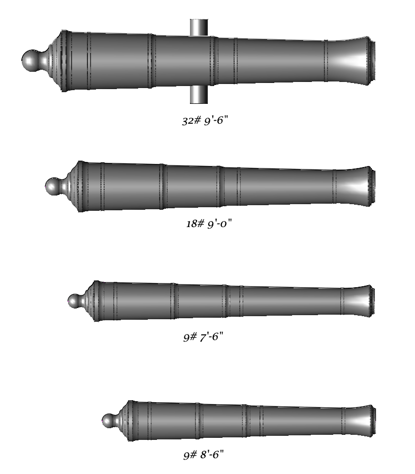
Oops, mis-labled. Here is the correct labeling.... Thanks for catching that, Alan! The long 9# were for the forecastle, presumably for chasing possibilities. The shorter 9# were on the quarterdeck.
-
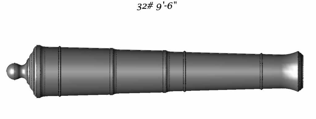
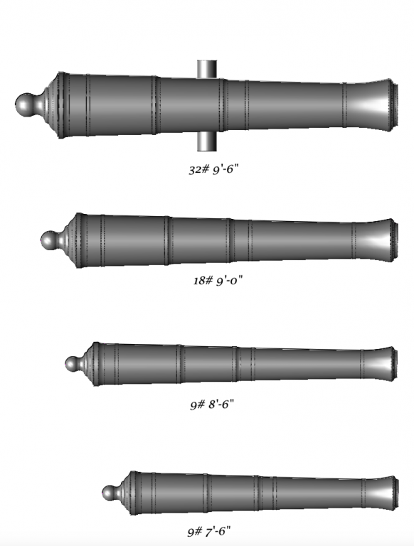
Thanks Allan, this is very helpful. However I proceed with forming the cannon, I first need new masters for all guns sizes. I have drawn the four needed for the Bellona: 32# 9'-6"; 18# 9'-0"; 9# 7'-6"; and 9# 8'-6". Finding the right proportions was a little challenging. These cannon would have been designed to a convention predating 1760, so some of the evolutions of the later 18th century would not have applied. Working with Brian Lavery's "The Arming and Fitting of English Ships of War 1600-1815", I discovered that the most likely patterns were developed by Albert Borgard in 1716, modified slightly by John Armstrong after 1725. The biggest changes came after the Bellona's time, with Thomas Blomefield after 1780. A little searching online found a Google digitized copy of Muller's "A Treatise of Artillery". In that book, Muller gives John Armstrong's proportions, and then offers criticism and proposals for changes. I only needed Armstrong's proportions, not Muller's proposed changes, so I was good to go. I don't know if or where Muller's proposals would have been implemented; he proposed removing the flair at the end of the muzzle, and placing the trunnions on the centerline of the gun, for example, neither of which seem to have happened in most of the 18th century. The digitized book did not reproduce the plates, so for further details on the cascable and the muzzle I turned to the drawings in Lavery's book of a 6# gun based on Bogard's proportions, and a print from the National Maritime Museum of drawing a muzzle and cascable from a 24# gun c 1770. (pages 93 and 94 in Lavery.) These vary primarily in the stave shapes in the cascable, the moulded sections between the base ring and the neck of the button. I chose the 1770 pattern, because it gives me a little more room to develop the mouldings at my small scale. I am assuming that this is not far off from what would have been cast in 1760. Interestingly, I looked at Harold Hahn's summary sheet for guns in "Ships of the American Revolution and Their Models" (p. 195). There are several key issues which do not correspond with the information in the Muller book. First, Hahn takes the given length (for example, 9'-6" for the 32# gun) as the total length including the cascable. Muller's book clearly says the given dimensions do not include the cascable; they are to the hind end of the base ring. Second, Hahn lists the caliber dimensions for various gun weights, for example, 6.105" for a 32# gun. This is a critical dimension, because all of the gun dimensions are based on the caliber. But Muller's book lists both caliber and shot dimension for each gun size, and the calibers are larger than the numbers listed by Hahn; for example the caliber listed for a 32# is 6.410". Indeed, it looks as if Hahn listed the shot dimension as if they were the caliber dimensions. I used the caliber sizes from the Muller book, and this consequently makes the guns slightly larger in their widths. Since the bore is the same as the caliber, it makes sense that the caliber is larger than the diameter of the shot, to provide windage clearance. Hahn reported that he got his information from an M.V. Brewington article in "American Neptune", 1943. I don't have access to that, so I can't confirm one way or the other if there was a different interpretation of caliber and shot size. Lacking any other information, I will go with the primary source I find in Muller. Mark

-
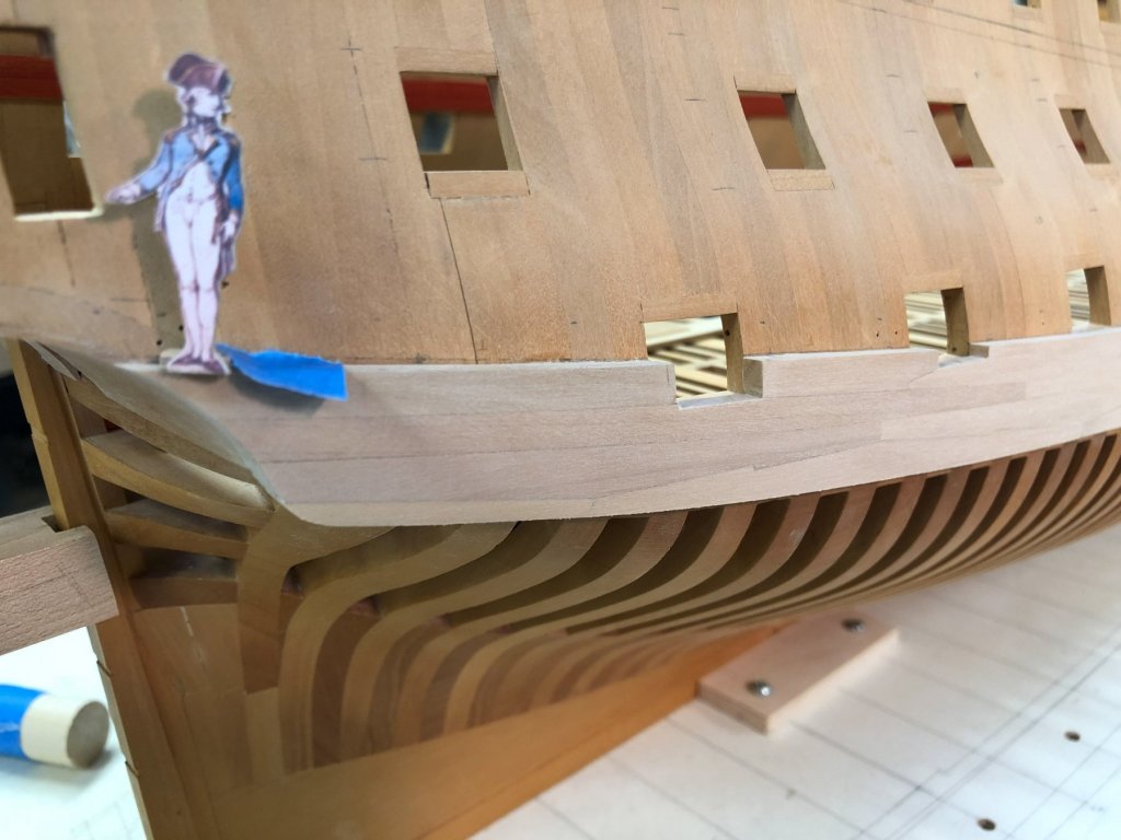
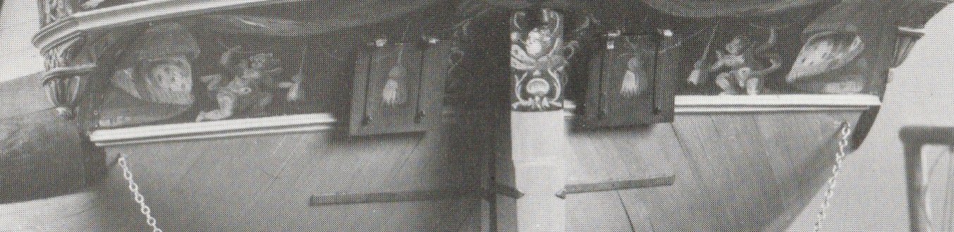
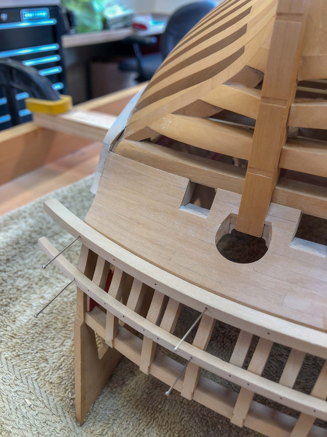
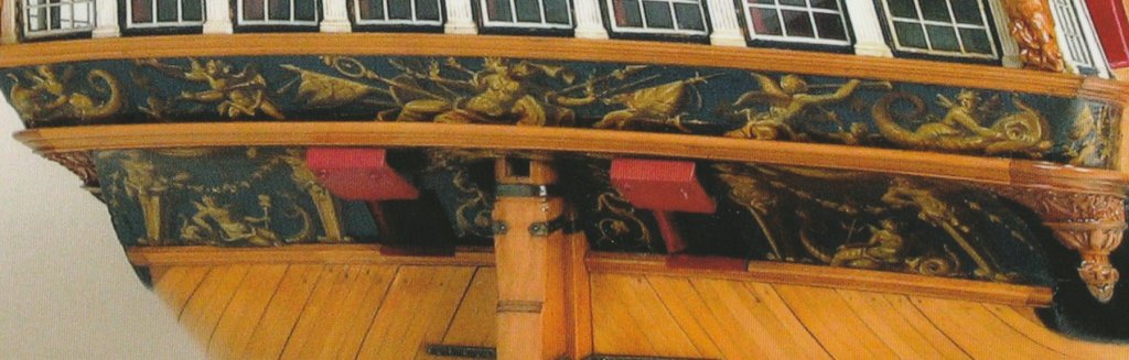
One more thought about the wales at that difficult-to visualize corner. I have sketched over my photo to show how the planking immediately under the wale rests on the TOP of the lower edge of the wale, and then curves away from the wale to abut into the lower counter. But the little blue triangle of planking abuts into the SIDE of the wale. This leaves a little piece of the wale kind of hanging out at the corner, just where it curves at its lowest, aftmost extremity. You can see this in the color cover photo of Rob Napier's "Legacy of a Ship Model, Examining HMS Princess Royal 1773", and in the black and white photo of Brian Lavery's "The 74 Gun Ship Bellona". Now i finally understand what is going on here, I have to say that I find this to be an awkward detail, both visually and functionally. These don't fair together gracefully, and the little triangle of planking with sharp acute angles is just asking for damage and rot. Perhaps it was the best the shipwrights could figure out for a very awkward design decision to chop off the stern to create those great stern galleries. A curved surface had to transform into a square one in a very small space in which to resolve the two. One can see why the rounded and elliptical sterns eventually replaced this in the early nineteenth century. I can imagine the original directive from the Admiralty to the shipwrights; "we want the stern galleries, so figure it out as best you can". One of the joys of building this model is to see how the shipwrights melded form and function together in almost all aspects, from the largest shapes to the finest details. Here is one place where function and beauty could not be fully resolved, in my humble opinion. But this is the only design detail that I have so far found that would earn a B in an otherwise A+ design. Mark

-
Thanks, druxey, I will look at that. I am sure I can move the pin holes to suit. Was there any profile to the drip edge, or just the full width of the moulding 1" below the counter? Mark
-
Thanks, Greg, there has been little movement in the hull parts for these many years, although the annual humidity changes continue to affect the overall hull length. Now that I have a lot of longitudinal members in place, like the deck clamps and the wales, the hull adjusts by opening up a few gaps in frames here and there. Once the upper planking is complete, I hope this will not be noticeable. The mouldings were sawn to the curves in both directions, and then refined on sanding blocks cut to the right curves. I don't remember how I made the sanding blocks, since they would have been a different radius due to the sloped inner face of the moulding. Maybe it was by trial and error. I sure hope I don't screw up when I try to cut the outer surfaces to the correct moulding profile.... Mark
-
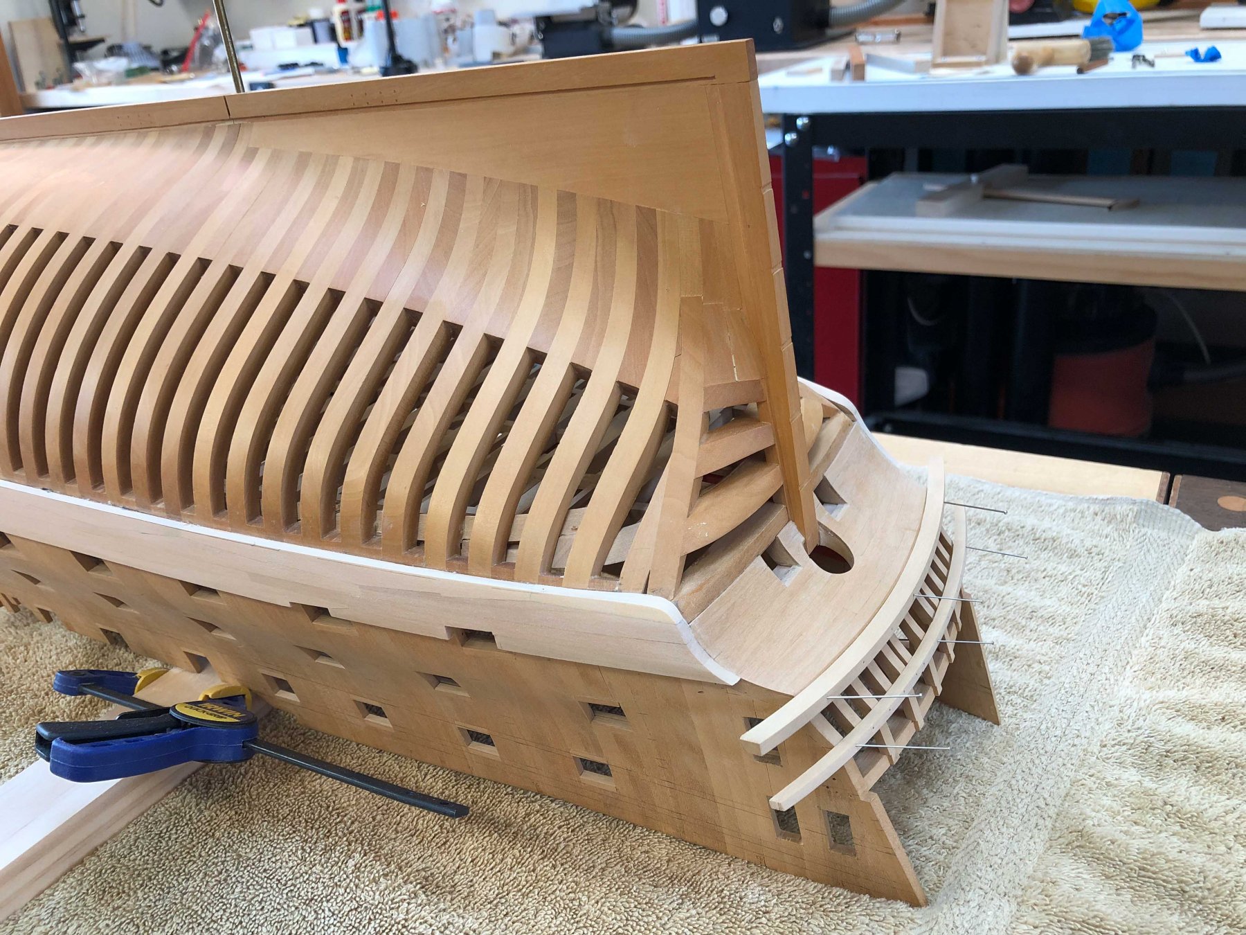
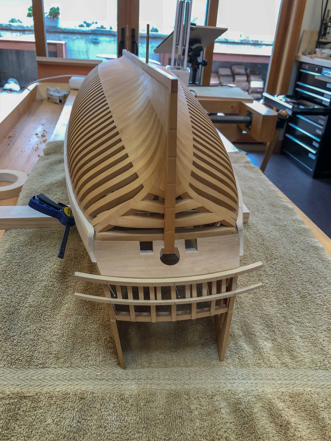
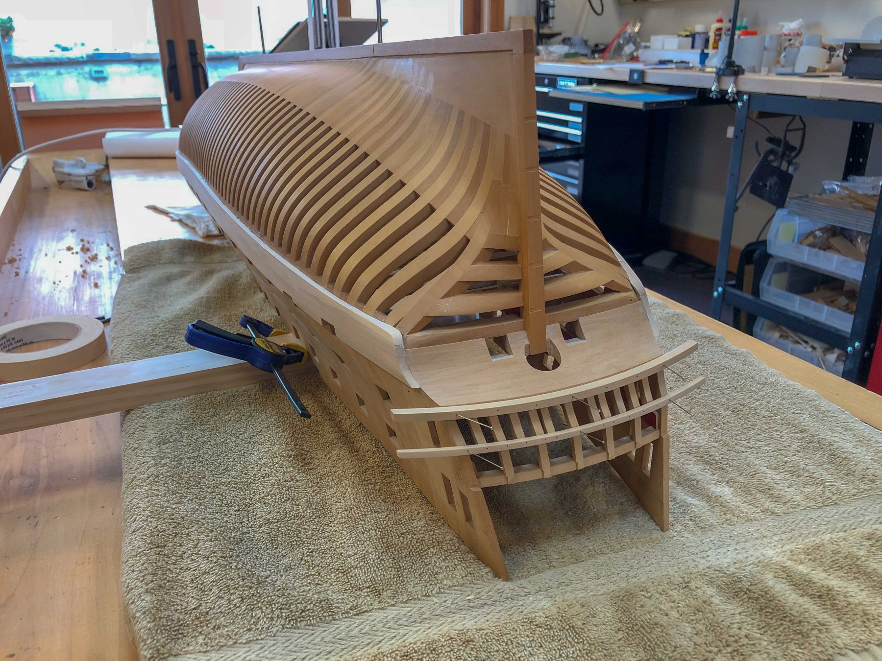
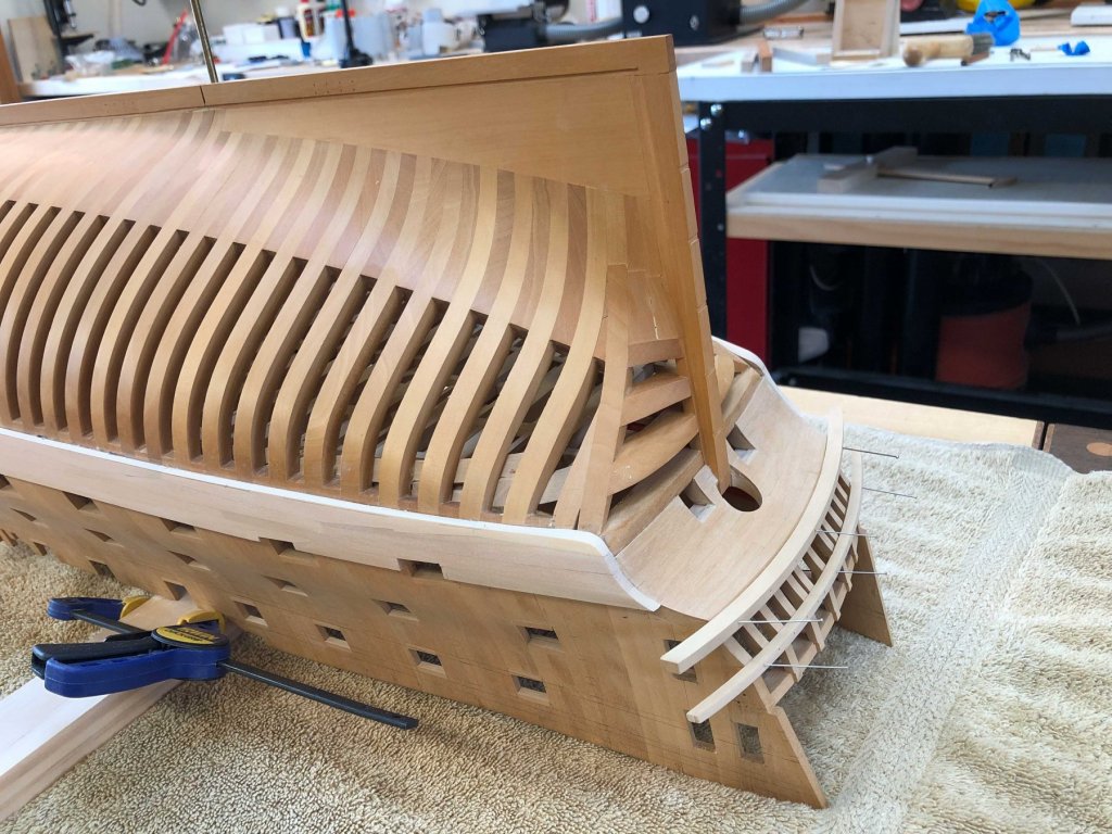
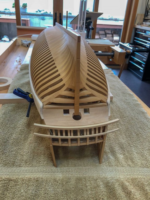
Thanks, Ed and druxey, I am resolved to do a better job on the cannon this time around. Good thing I had to put that project aside while retiring and moving. A little time away made it very clear that I needed to do better. And now I have renewed energy to tackle it again. Thanks, John, for your kind comments. I have come to think of this as a lot of separate parts, each of which needs full time and attention. I have continued to be inspired by Remco's comment "Treat each part as if it is a model on its own, you will finish more models in a day than others do in a lifetime". Here are a few pictures of the wales refined a little more at the stern. I temporarily attached the mouldings at the stern, made many years ago and just waiting for their time again. Reflecting on the wales, now they are almost done, It is pretty remarkable how a series of relatively short planks can be fitted together not only for structural strength longitudinally, but also how they can accommodate to a hull curving gracefully in several directions. The individual parts recede in emphasis, revealing the beauty of the collective whole. Like so many things on these models, the individual parts will likely not show themselves in the final model, but we all know they are there! Mark


-
Mike, very nice, crisp joinery. Looking great! Mark
- 607 replies
-
- 7
-

-
- winchelsea
- Syren Ship Model Company
- (and 1 more)
-
thanks, druxey, I have now completed the lowest pieces, except for some final refinement of the lower sweeping curve. I can see why this had to be carved in the real ship; the lieutenant standing on top of the wale shows how large this lower piece is, and it curves all over the place. Since I am not planking the lower hull, it does look a little strange to have the wales hanging down at the stern at the corners, but they would obviously have done so to house the ends of the lower planking. Thanks, Ed, this is very helpful. And I apologize; I had entirely forgotten about the instructions in the Sherline manual. I think at the time I bought the machine, I did not think I would ever be making my own cutters, and so eventually forgot about it. My needs and confidence have risen since purchasing the machine. A few more days cleaning up the wales, and it is time to think about the cannon again. I have decided to re-cut the master, since my first efforts necked in the muzzle end too much. So I will get a little more experience with cutting a gun on the lathe, and think about whether I want to go that direction or try casting again, from a new master. Good thing I am retired and in no rush. And thanks, Michael, it is fun to see the hull upside down again. Somehow the full beauty of the hull does not quite show up when it is right side up. Mark